Compaq Confidential Need to Know Required
Writer: Bob Young Project: RAID Array 3000 Pedestal Storage Subsystem Hardware User's Guide Comments:
Part Number: EK-SMCPO-UG. C01 File Name: a-frnt Last Saved On: 12/8/00 9:53 AM
Compaq StorageWorks
™
RAID Array 3000 Pedestal Storage
Subsystem Hardware
Users Guide
Third Edition (January 2001)
Part Number EK-SMCPO-UG. C01
Compaq Computer Corporation

Compaq Confidential Need to Know Required
Writer: Bob Young Project: RAID Array 3000 Pedestal Storage Subsystem Hardware User's Guide Comments:
Part Number: EK-SMCPO-UG. C01 File Name: a-frnt Last Saved On: 12/8/00 9:53 AM
© 2001 Compaq Computer Corporation.
COMPAQ, the Compaq logo and StorageWorks Registered with the U.S. Patent and
Trademark Office.
Microsoft, MS-DOS, Windows, and Windows NT are trademarks of Microsoft Corporation.
All other product names mentioned herein may be trademarks of their respective companies.
Confidential computer software. Valid license from Compaq required for possession, use or
copying. Consistent with FAR 12.211 and 12.212, Commercial Computer Software,
Computer Software Documentation, and Technical Data for Commercial Items are licensed to
the U.S. Government under vendor's standard commercial license.
Compaq shall not be liable for technical or editorial errors or omissions contained herein. The
information in this document is subject to change without notice.
THE INFORMATION IN THIS PUBLICATION IS PROVIDED “AS IS” WITHOUT
WARRANTY OF ANY KIND. THE ENTIRE RISK ARISING OUT OF THE USE OF THIS
INFORMATION REMAINS WITH RECIPIENT. IN NO EVENT SHALL COMPAQ BE
LIABLE FOR ANY DIRECT, CONSEQUENTIAL, INCIDENTAL, SPECIAL, PUNITIVE
OR OTHER DAMAGES WHATSOEVER (INCLUDING WITHOUT LIMITATION,
DAMAGES FOR LOSS OF BUSINESS PROFITS, BUSINESS INTERRUPTION OR LOSS
OF BUSINESS INFORMATION), EVEN IF COMPAQ HAS BEEN ADVISED OF THE
POSSIBILITY OF SUCH DAMAGES AND WHETHER IN AN ACTION OF CONTRACT
OR TORT, INCLUDING NEGLIGENCE.
The limited warranties for Compaq products are exclusively set forth in the
documentation accompanying such products. Nothing herein should be construed as
constituting a further or additional warranty.
RAID Array 3000 Pedestal Storage Subsystem Hardware User's Guide
Third Edition (January 2001)
Part Number EK-SMCPO-UG. C01

Compaq Confidential Need to Know Required
Writer: Bob Young Project: RAID Array 3000 Pedestal Storage Subsystem Hardware User's Guide Comments:
File Name: a-frnt Last Saved On: 12/8/00 9:53 AM
Contents
About This Guide
Purpose and Scope.......................................................................................................ix
Intended Audience .......................................................................................................ix
Document Structure .....................................................................................................ix
Related Documents ......................................................................................................xi
Text Conventions........................................................................................................xii
Symbols in Text ........................................................................................................ xiii
Symbols on Equipment............................................................................................. xiii
Rack Stability..............................................................................................................xv
Getting Help................................................................................................................xv
Compaq Technical Support .................................................................................xv
Compaq Website.................................................................................................xvi
Compaq Authorized Reseller .............................................................................xvi
Chapter 1
Product Overview
Product Description .................................................................................................. 1-1
Pedestal Features....................................................................................................... 1-4
Pedestal Cabinet........................................................................................................ 1-5
Pedestal Components................................................................................................ 1-7
StorageWorks Building Blocks (SBBs) ............................................................ 1-7
RAID Array Controller...................................................................................... 1-7
Pedestal Power Supplies.................................................................................... 1-8
UPS.................................................................................................................... 1-8
Environmental Monitor Unit (EMU)................................................................. 1-9
UltraSCSI Buses .............................................................................................. 1-11
Connecting the Pedestal to a Host System ............................................................. 1-14
Specifications.......................................................................................................... 1-19

iv RAID Array 3000 Pedestal Storage Subsystem Hardware User's Guide
Compaq Confidential Need to Know Required
Writer: Bob Young Project: RAID Array 3000 Pedestal Storage Subsystem Hardware User's Guide Comments:
Part Number: EK-SMCPO-UG. C01 File Name: a-frnt Last Saved On: 12/8/00 9:53 AM
Chapter 2
RAID Array Controller
Controller Overview ..................................................................................................2-1
Controller Features ....................................................................................................2-3
Controller Reset and LED Indicators ........................................................................2-8
Flexible RAID Set Configuration..............................................................................2-9
Performance Enhancements ....................................................................................2-10
Custom Components ........................................................................................2-10
Efficient Write and Read Algorithms...............................................................2-11
RAID Levels Supported ..........................................................................................2-13
RAID 0 .............................................................................................................2-14
RAID 1 .............................................................................................................2-16
RAID 0+1 .........................................................................................................2-16
RAID 4 .............................................................................................................2-18
RAID 5 .............................................................................................................2-19
Just a Bunch of Drives (JBOD)........................................................................2-21
Redundant Operation...............................................................................................2-21
Initialization......................................................................................................2-21
Message Passing...............................................................................................2-22
Failover.............................................................................................................2-22
Environmental..........................................................................................................2-22
Backup Power Management.............................................................................2-22
Voltage Monitoring ..........................................................................................2-24
Temperature Monitoring ..................................................................................2-26
Chapter 3
Maintenance
Pedestal Status and Power LEDs...............................................................................3-2
SBB Status LEDs.......................................................................................................3-3
Controller LEDs.........................................................................................................3-4
EMU Error Reporting................................................................................................3-5
EMU Error Conditions .......................................................................................3-6
Replacing Components (FRUs).................................................................................3-7
Removing the Pedestal Door..............................................................................3-8
Replacing an SBB ..............................................................................................3-9
Replacing a Power Supply ...............................................................................3-10
Replacing the RAID Array Controller .............................................................3-12
Replacing the EMU Board ...............................................................................3-13
Replacing the UPS............................................................................................3-15
Differential/Wide UltraSCSI Bus............................................................................3-15
Reconfiguring the SCSI Bus ............................................................................3-16
Replacing the Controller Memory Cache Modules.................................................3-20

Contents v
Compaq Confidential Need to Know Required
Writer: Bob Young Project: RAID Array 3000 Pedestal Storage Subsystem Hardware User's Guide Comments:
Part Number: EK-SMCPO-UG. C01 File Name: a-frnt Last Saved On: 12/8/00 9:53 AM
Chapter 4
Expansion Pedestal Option
Product Description .................................................................................................. 4-1
Expansion Pedestal Cabinet...................................................................................... 4-2
Expansion Pedestal Components.............................................................................. 4-4
Reconfiguring Base Pedestal UltraSCSI Bus ........................................................... 4-6
Chapter 5
Second Controller Option
Second Controller Option Kit................................................................................... 5-2
Installing the Upgrade............................................................................................... 5-3
Saving Existing Configuration .......................................................................... 5-3
Updating Firmware............................................................................................ 5-4
Shutting Down the RA3000 .............................................................................. 5-6
Installing Two SIMMs into Second Controller................................................. 5-7
Replacing Existing Controller ........................................................................... 5-8
Restoring the Configuration .............................................................................. 5-9
Updating Firmware on Second Controller ...................................................... 5-10
Installing Original Controller .......................................................................... 5-11
Configuring a Dual Controller Installation for a Single Serial Port....................... 5-11
Configuring the RA3000 for the Active Mode of Operation .......................... 5-12
Configuring the Dual Controllers.................................................................... 5-13
Connecting to Your Dual Controller Storage System ..................................... 5-14
Verifying the Controller Operating Parameters .............................................. 5-15
List of Figures
Figure 1-1. RAID Array 3000 pedestal enclosure (drives optional) ....................... 1-2
Figure 1-2. Pedestal front panel major components ................................................ 1-6
Figure 1-3. Pedestal rear panel power supplies ....................................................... 1-6
Figure 1-4. EMU circuit board location ................................................................ 1-10
Figure 1-5. Pedestal rear panel components.......................................................... 1-11
Figure 1-6. UltraSCSI bus port and default SCSI ID assignments........................ 1-12
Figure 1-7. UltraSCSI bus configuration switch ................................................... 1-13
Figure 1-8. Slot locations and SCSI ID addresses................................................. 1-13
Figure 1-9. Single host, single adapter cabling diagram ....................................... 1-15
Figure 1-10. Single host, dual adapter/dual controller cabling diagram ............... 1-16
Figure 1-11. Single host, single adapter/dual controller (y-cable
connection) cabling diagram ........................................................... 1-17
Figure 1-12. Dual host, single adapter/single controller cabling diagram ............ 1-18
Figure 2-1. Bridging the gap between the host and the pedestal............................. 2-3
Figure 2-2. Units created from storagesets, partitions, and disk drives .................. 2-4
Figure 2-3. Controller front panel............................................................................ 2-9

vi RAID Array 3000 Pedestal Storage Subsystem Hardware User's Guide
Compaq Confidential Need to Know Required
Writer: Bob Young Project: RAID Array 3000 Pedestal Storage Subsystem Hardware User's Guide Comments:
Part Number: EK-SMCPO-UG. C01 File Name: a-frnt Last Saved On: 12/8/00 9:53 AM
Figure 2-4. RAID 0 write .......................................................................................2-15
Figure 2-5. Diagram of a RAID 1 write .................................................................2-16
Figure 2-6. Diagram of RAID 0+1 write................................................................2-17
Figure 2-7. Diagram of a RAID 4 write .................................................................2-18
Figure 2-8. Diagram of a RAID 5 write .................................................................2-20
Figure 3-1. Pedestal status LEDs..............................................................................3-3
Figure 3-2. Disk drive status LEDs ..........................................................................3-4
Figure 3-3. Removing pedestal door ........................................................................3-8
Figure 3-4. Replacing an SBB................................................................................3-10
Figure 3-5. Replacing a power supply....................................................................3-11
Figure 3-6. Removing the controller from the pedestal .........................................3-12
Figure 3-7. Remove standoffs from UPS and external fault connectors................3-14
Figure 3-8. Remove screw and panel .....................................................................3-18
Figure 3-9. Location of SCSI bus configuration switch.........................................3-19
Figure 3-10. Configuration switch .........................................................................3-19
Figure 3-11. Remove controller..............................................................................3-20
Figure 3-12. Release locking clips .........................................................................3-21
Figure 13. Remove installed SIMM modules.........................................................3-21
Figure 3-14. Install replacement SIMM .................................................................3-22
Figure 3-15. Pivot SIMM down to secure ..............................................................3-23
Figure 4-1. Expansion pedestal ................................................................................4-2
Figure 4-2. Expansion pedestal slot locations and ID addresses..............................4-3
Figure 4-3. Rear panel power supplies .....................................................................4-4
Figure 4-4. EMU circuit board location ...................................................................4-5
Figure 4-5. Remove side cover from base pedestal..................................................4-7
Figure 4-6. Remove SCSI bus terminator ................................................................4-7
Figure 4-7. Disconnect SCSI cable ..........................................................................4-8
Figure 4-8. Connect SCSI jumper ............................................................................4-9
Figure 4-9. Remove connector knockout plate.......................................................4-10
Figure 4-10. Connect SCSI cable ...........................................................................4-11
Figure 4-11. Set configuration switch to 7 .............................................................4-12
Figure 4-12. Configuration switch .........................................................................4-12
Figure 4-13. Reconfigured SCSI bus addresses .....................................................4-13
Figure 4-14. Connect SCSI cable between pedestals .............................................4-14
Figure 4-15. Power cable connections....................................................................4-15
Figure 4-16. Transfer drives from base to expansion pedestal...............................4-16
Figure 5-1. Second controller pedestal slot location ................................................5-2
Figure 5-2. Saving the existing configuration ..........................................................5-3
Figure 5-3. Saved configuration ...............................................................................5-4
Figure 5-4. Update firmware command ...................................................................5-4
Figure 5-5. Firmware update dialog box ..................................................................5-5
Figure 5-6. Insert SIMM into connector...................................................................5-7
Figure 5-7. Pivot SIMM down to seat ......................................................................5-7
Figure 5-8 Remove controller from top slot.............................................................5-8
Figure 5-9. Restoring configuration to new controller.............................................5-9
Figure 5-10. Restored configuration example ........................................................5-10

Contents vii
Compaq Confidential Need to Know Required
Writer: Bob Young Project: RAID Array 3000 Pedestal Storage Subsystem Hardware User's Guide Comments:
Part Number: EK-SMCPO-UG. C01 File Name: a-frnt Last Saved On: 12/8/00 9:53 AM
List of Tables
Table 1 Related Documents.........................................................................................xi
Table 1-1 RAID Array 3000 Pedestal Part Numbers and Model
Descriptions .............................................................................................. 1-3
Table 1-2 Single Host, Single Adapter Cabling ..................................................... 1-15
Table 1-3 Single Host, Dual Adapter/Dual Controller Cabling ............................. 1-16
Table 1-4 Single Host, Single Adapter/Dual Controller (Y-cable connection
cabling) ................................................................................................... 1-17
Table 1-5 Dual Host, Single Adapter/Single Controller Cabling........................... 1-18
Table 1-6 Pedestal Technical Specifications .......................................................... 1-19
Table 1-7 Pedestal Physical and Power Specification............................................ 1-20
Table 2-1 Controller Specifications.......................................................................... 2-5
Table 2-2 LED/Reset Switch Interface..................................................................... 2-8
Table 2-3 RAID Levels Supported ......................................................................... 2-13
Table 2-4 Pedestal RAID Set Restrictions ............................................................. 2-13
Table 2-5 RAID 0+1 Example................................................................................ 2-17
Table 2-6 Response to Various AC Power Conditions .......................................... 2-23
Table 2-7 Acceptable System Voltage Levels........................................................ 2-24
Table 2-8 Acceptable Termination Voltage Levels................................................ 2-25
Table 2-9 Acceptable 12 Volt Levels ..................................................................... 2-25
Table 2-10 Acceptable External Temperature Levels ............................................ 2-26
Table 2-11 Acceptable Board Temperature Levels................................................ 2-26
Table 3-1 Disk Drive SBB Status LEDs................................................................... 3-4
Table 3-2 SCSI Bus Length and External Cables................................................... 3-16
Table 3-3 Assigned Slot Device Addresses in the Pedestal ................................... 3-16


Compaq Confidential Need to Know Required
Writer: Bob Young Project: RAID Array 3000 Pedestal Storage Subsystem Hardware User's Guide Comments:
File Name: a-frnt Last Saved On: 12/8/00 9:53 AM
About This Guide
Purpose and Scope
This guide is designed to for installers and operators of Compaq
StorageWorks
TM
RAID Array 3000 Pedestal Storage Subsystem Hardware
User’s Guide.
Intended Audience
This document is written for installers and operators.
Document Structure
This guide contains the following information:
Chapter 1: Product Overview
n
Product Description
n
Pedestal Features
n
Pedestal Cabinet
n
Pedestal Components
n
Connecting the Pedestal to a Host System
n
Specifications

x RAID Array 3000 Pedestal Storage Subsystem Hardware User's Guide
Compaq Confidential Need to Know Required
Writer: Bob Young Project: RAID Array 3000 Pedestal Storage Subsystem Hardware User's Guide Comments:
Part Number: EK-SMCPO-UG. C01 File Name: a-frnt Last Saved On: 12/8/00 9:53 AM
Chapter 2: RAID Array Controller
n
Controller Overview
n
Controller Features
n
Controller Reset and LED Indicators
n
Flexible RAID Set Configuration
n
Performance Enhancements
n
RAID Levels Supported
n
Redundant Operation
n
Environmental
Chapter 3: Maintenance
n
Pedestal Status and Power LEDs
n
SBB Status LEDs
n
Controller LEDs
n
EMU Error Reporting
n
Replacing Components (FRUs)
n
Differential/Wide UltraSCSI Bus
n
Replacing the Controller Memory Cache Modules
Chapter 4: RAID Array Controller
n
Product Description
n
Expansion Pedestal Cabinet
n
Expansion Pedestal Components
n
Reconfiguring Base Pedestal UltraSCSI Bus
Chapter 5: Second Controller Option
n
Second Controller Option Kit
n
Installing the Upgrade
n
Configuring a Dual Controller Installation for a Single Serial Port

Contents xi
Compaq Confidential Need to Know Required
Writer: Bob Young Project: RAID Array 3000 Pedestal Storage Subsystem Hardware User's Guide Comments:
Part Number: EK-SMCPO-UG. C01 File Name: a-frnt Last Saved On: 12/8/00 9:53 AM
Related Documents
In addition to this guide, the following documentation is useful to the reader:
Table 1
Related Documents
Document Title Part Number
RAID Array 3000 Subsystem Second
Controller Option Installation Guide
EK-SM3KC-IG.E01
RAID Array 3000 Controller Shelf Hardware
Users Guide
EK-SMCPQ-UG.D01
Command Console V2.2 for the RAID Array
3000 (Pedestal and Rack Mount Models)
Users Guide
AA-RBF2C-TE

xii RAID Array 3000 Pedestal Storage Subsystem Hardware User's Guide
Compaq Confidential Need to Know Required
Writer: Bob Young Project: RAID Array 3000 Pedestal Storage Subsystem Hardware User's Guide Comments:
Part Number: EK-SMCPO-UG. C01 File Name: a-frnt Last Saved On: 12/8/00 9:53 AM
Text Conventions
This document uses the following conventions to distinguish elements of text:
Keys Keys appear in boldface. A plus sign (+) between
two keys indicates that they should be pressed
simultaneously.
USER INPUT User input appears in a different typeface and in
uppercase.
FILENAMES File names appear in uppercase italics.
Menu Options,
Command Names,
Dialog Box Names
These elements appear in initial capital letters.
COMMANDS,
DIRECTORY NAMES,
and DRIVE NAMES
These elements appear in uppercase, unless case
sensitive.
Type When you are instructed to type information, type
the information without pressing the Enter key.
Enter When you are instructed to enter information, type
the information and then press the Enter key.

Contents xiii
Compaq Confidential Need to Know Required
Writer: Bob Young Project: RAID Array 3000 Pedestal Storage Subsystem Hardware User's Guide Comments:
Part Number: EK-SMCPO-UG. C01 File Name: a-frnt Last Saved On: 12/8/00 9:53 AM
Symbols in Text
The following symbols are found in the text of this guide to indicate different
types of information.
WARNING:
Text set off in this manner indicates that failure to follow directions
in the warning could result in bodily harm or loss of life.
CAUTION:
Text set off in this manner indicates that failure to follow directions
could result in damage to equipment or loss of information.
IMPORTANT:
Text set off in this manner presents clarifying information or specific
instructions.
NOTE:
Text set off in this manner presents commentary, sidelights, or interesting points
of information.
Symbols on Equipment
The following symbols are placed on equipment to indicate the presence of
potentially hazardous conditions:
This symbol in conjunction with any of the following symbols indicates the
presence of a potential hazard. The potential for injury exists if warnings
are not observed. Consult your documentation for specific details.
This symbol indicates the presence of hazardous energy circuits or electric
shock hazards. Refer all servicing to qualified personnel.
WARNING:
To reduce the risk of injury from electric shock hazards, do not
open this enclosure. Refer all maintenance, upgrades, and servicing to
qualified personnel.
This symbol indicates the presence of electric shock hazards. The area
contains no user or field serviceable parts. Do not open for any reason.
WARNING:
To reduce the risk of injury from electric shock hazards, do
not open this enclosure.

xiv RAID Array 3000 Pedestal Storage Subsystem Hardware User's Guide
Compaq Confidential Need to Know Required
Writer: Bob Young Project: RAID Array 3000 Pedestal Storage Subsystem Hardware User's Guide Comments:
Part Number: EK-SMCPO-UG. C01 File Name: a-frnt Last Saved On: 12/8/00 9:53 AM
This is a test
This symbol on an RJ-45 receptacle indicates a Network Interface
Connection.
WARNING:
To reduce the risk of electric shock, fire, or damage to the
equipment, do not plug telephone or telecommunications connectors into
this receptacle.
This symbol indicates the presence of a hot surface or hot component. If
this surface is contacted, the potential for injury exists.
WARNING:
To reduce the risk of injury from a hot component, allow the
surface to cool before touching.
These symbols on power supplies or systems indicate the
equipment is supplied by multiple sources of power.
WARNING:
To reduce the risk of injury from electric shock,
remove all power cords to completely disconnect power from
the system.
Weight in kg
Weight in lb
This symbol indicates that the component exceeds the recommended
weight for one individual to handle safely.
WARNING:
To reduce the risk of personal injury or damage to the
equipment, observe local occupational health and safety requirements and
guidelines for manual material handling.

Contents xv
Compaq Confidential Need to Know Required
Writer: Bob Young Project: RAID Array 3000 Pedestal Storage Subsystem Hardware User's Guide Comments:
Part Number: EK-SMCPO-UG. C01 File Name: a-frnt Last Saved On: 12/8/00 9:53 AM
Rack Stability
WARNING:
To reduce the risk of personal injury or damage to the equipment,
be sure that:
n
The leveling jacks are extended to the floor.
n
The full weight of the rack rests on the leveling jacks.
n
The stabilizing feet are attached to the rack if it is a single rack
installation.
n
The racks are coupled together in multiple rack installations.
n
Only one component is extended at a time. A rack may become unstable
if more than one component is extended for any reason.
Getting Help
If you have a problem and have exhausted the information in this guide, you
can get further information and other help in the following locations.
Compaq Technical Support
In North America, call the Compaq Technical Phone Support Center at
1-800-OK-COMPAQ. This service is available 24 hours a day, 7 days a week.
For continuous quality improvement, calls may be recorded or monitored.
Outside North America, call the nearest Compaq Technical Support Phone
Center. Telephone numbers for worldwide Technical Support Centers are
listed on the Compaq website. Access the Compaq website:
http://www.compaq.com

xvi RAID Array 3000 Pedestal Storage Subsystem Hardware User's Guide
Compaq Confidential Need to Know Required
Writer: Bob Young Project: RAID Array 3000 Pedestal Storage Subsystem Hardware User's Guide Comments:
Part Number: EK-SMCPO-UG. C01 File Name: a-frnt Last Saved On: 12/8/00 9:53 AM
Be sure to have the following information available before you call Compaq:
n
Technical support registration number (if applicable)
n
Product serial number
n
Product model name and number
n
Applicable error messages
n
Add-on boards or hardware
n
Third-party hardware or software
n
Operating system type and revision level
Compaq Website
The Compaq website has information on this product. Access the Compaq
website:
http://www.compaq.com/storage
Compaq Authorized Reseller
For the name of your nearest Compaq authorized reseller:
n
In the United States, call 1-800-345-1518.
n
In Canada, call 1-800-263-5868.
n
Elsewhere, see the Compaq website for locations and telephone
numbers.

Compaq Confidential – Need to Know Required
Writer: Bob Young Project: RAID Array 3000 Pedestal Storage Subsystem Hardware User’s Guide Comments:
Part Number: EK-SMCPO-UG. C01 File Name: b-ch1 Product Overview.doc Last Saved On: 12/4/00 1:51 PM
Chapter 1
Product Overview
This chapter provides an overall description of the RAID Array 3000 Storage
System and its components. Examples of Host/Storage System connections
and a list of technical and environmental specifications are included at the end
of the chapter.
NOTE: This guide is the Hardware User’s Guide. For configuration information, refer to the
Getting Started RAID Array 3000 Installation Guide for your Host system and the
Command Console V2.2 for the RAID Array 3000 (Pedestal and Rack Mount Models)
User’s Guide.
Product Description
The RAID Array 3000 storage subsystem is a desk-side storage system
(subsystem) offering the basic components required to create a user-designed
storage array with two 16-bit, differential UltraSCSI bus host interfaces
(Figure 1–1). The pedestal can accommodate up to seven 3½-in storage
devices. The devices, referred to as StorageWorks Building Blocks or SBBs,
are disk drives from the StorageWorks family of storage devices. The release
note that accompanies the subsystem lists the software solutions and disk
drives that are supported. A battery backup subsystem is included as part of
the pedestal enclosure in the form of a freestanding Uninterruptable Power
Supply (UPS). In case of a power failure, the UPS provide a temporary backup
for cache while the subsystem flushes to disks.

1-2 RAID Array 3000 Pedestal Storage Subsystem Hardware User’s Guide
Compaq Confidential – Need to Know Required
Writer: Bob Young Project: RAID Array 3000 Pedestal Storage Subsystem Hardware User’s Guide Comments:
Part Number: EK-SMCPO-UG. C01 File Name: b-ch1 Product Overview.doc Last Saved On: 12/4/00 1:51 PM
The RAID Array 3000 offering also includes option kits designed to increase
the storage capacity and enhance the performance of the subsystem. The first
is an expansion pedestal (second enclosure) designed to increase the storage
capacity of the subsystem to a maximum of 14 drives. The pedestal expansion
kit option is described in detailed in Chapter 4 “Expansion Pedestal Option” of
this guide.
The second option kit allows the addition of a second RAID controller to the
subsystem for redundancy. The second controller operates in conjunction with
the installed controller to protect data during a malfunction. Chapter 5 “Second
Controller Option” describes how to install the redundant controller option and
how to reconfigure the subsystem to accommodate it.
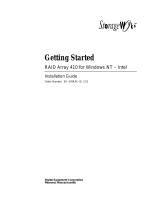
The RAID Array 3000 pedestal enclosure and its associated options are listed
and described in Table 1–1. Figure 1–1 shows the pedestal with a full
complement of drives (optional) for completeness.
PEDESTAL
UPS
3000
-
0
1A
Figure 1-1. RAID Array 3000 pedestal enclosure (drives optional)

Product Overview 1-3
Compaq Confidential – Need to Know Required
Writer: Bob Young Project: RAID Array 3000 Pedestal Storage Subsystem Hardware User’s Guide Comments:
Part Number: EK-SMCPO-UG. C01 File Name: b-ch1 Product Overview.doc Last Saved On: 12/4/00 1:51 PM
The RAID Array 3000 pedestal is equipped with a dual-channel RAID
controller that supports all of the UltraSCSI bus features. It also contains an
Environmental Monitor Unit (EMU) board for environmental monitoring and
error detection.
Table 1-1
RAID Array 3000 Pedestal Part Numbers and Model Descriptions
Compaq Part No. Item Description
DS-SWXRA-GA
RA3000 pedestal subsystem with one controller, 120 V.
Includes: Seven-slot pedestal for wide UltraSCSI SBBs, one HSZ22
two-channel controller with 16 MB cache, Environmental Monitor Unit
(EMU), two 204 watt power supplies with fans, five meter host SCSI
cable (BN37A), BN38E-OB adapter, one 120-volt UPS, and North
American power cords. Disks are not included.
Requires: Solutions Software Kit for platform, host adapter, and disks.
Options: Second HSZ22 controller, seven disk SBB expansion pedestal,
and cache memory upgrade.
DS-SWXRA-GC RA3000 pedestal subsystem with one controller, 230 V.
Includes: Seven-slot pedestal for wide UltraSCSI SBBs, one HSZ22
two-channel controller with 16 MB cache, Environmental Monitor Unit
(EMU), two 204 watt power supplies with fans, five meter host SCSI
cable (BN37A), BN38E-OB adapter, one 230-volt Uninterruptable Power
Supply (UPS), and North American power cords. Disks are not included.
Requires: Solutions Software Kit for platform, host adapter, and disks.
Options: Second HSZ22 controller, seven-disk SBB expansion
pedestal, and cache memory upgrade.
DS-HSZ22-AA RA3000 second controller option which includes:
DS-HSZ22-AA SCSI controller, three 16-MB SIMM modules, 0.8 m
adapter-to-SCSI-3 cable, 5 m SCSI cable, 9-pin serial cable, user
documentation.
DS-HSZ22-AB RA3000 second controller option which includes:
DS-HSZ22-AB SCSI controller, four 32-MB SIMM modules, 0.8 m
adapter-to-SCSI-3 cable, 5 m SCSI cable, 9-pin serial cable, user
documentation.
DS-SWXRA-GD
Expansion Pedestal (120/240 V) with slot space for seven additional
UltraSCSI disk drives.
DS-SWXRA-GR Single 204-watt power supply for RA3000, 120/230 V for on-site spare.

1-4 RAID Array 3000 Pedestal Storage Subsystem Hardware User’s Guide
Compaq Confidential – Need to Know Required
Writer: Bob Young Project: RAID Array 3000 Pedestal Storage Subsystem Hardware User’s Guide Comments:
Part Number: EK-SMCPO-UG. C01 File Name: b-ch1 Product Overview.doc Last Saved On: 12/4/00 1:51 PM
Pedestal Features
The major features of the pedestal are:
■ Two differential 16-bit UltraSCSI host buses
■ Seven 3½-in disk drive SBB slots
■ One dual-channel RAID array controller
■ Second controller option for redundancy
■ Expansion pedestal option allowing up to fourteen SBB slots in a dual-
pedestal subsystem configuration
■ Memory cache expansion option for the controller
■ Redundant power provided by two fan-cooled universal AC input power
supplies (50/60 Hz, 100 to 240 VAC)
■ Cache backup provided by an external UPS
■ Environmental monitor unit (EMU) for error detection
■ The ability to hot plug SBBs without powering down the system
Pedestal Cabinet
The pedestal cabinet is a modular freestanding storage enclosure that is
completely self-contained. It has two fan-cooled power supplies, an internal
EMU circuit board, and a RAID array controller with front panel display and
control.
Figure 1–2 shows the major components in the pedestal enclosure.
Figure 1–3 identifies the items on the rear panel power supplies. The
characteristics of the pedestal cabinet are:
■ The disk drive storage capacity is seven 3½-in disk drive SBBs.
■ The subsystem slots are numbered 0 through 6 from top to bottom.
■ There are two 68-pin VHDCI female SCSI connectors on the rear panel,
which interconnect the host system to the RAID controller in the
pedestal.
■ The rear panel also contains an alarm switch, a UPS monitor connector,
an external fault condition connector, and a serial port connector (for
controller configuration).
Page is loading ...
Page is loading ...
Page is loading ...
Page is loading ...
Page is loading ...
Page is loading ...
Page is loading ...
Page is loading ...
Page is loading ...
Page is loading ...
Page is loading ...
Page is loading ...
Page is loading ...
Page is loading ...
Page is loading ...
Page is loading ...
Page is loading ...
Page is loading ...
Page is loading ...
Page is loading ...
Page is loading ...
Page is loading ...
Page is loading ...
Page is loading ...
Page is loading ...
Page is loading ...
Page is loading ...
Page is loading ...
Page is loading ...
Page is loading ...
Page is loading ...
Page is loading ...
Page is loading ...
Page is loading ...
Page is loading ...
Page is loading ...
Page is loading ...
Page is loading ...
Page is loading ...
Page is loading ...
Page is loading ...
Page is loading ...
Page is loading ...
Page is loading ...
Page is loading ...
Page is loading ...
Page is loading ...
Page is loading ...
Page is loading ...
Page is loading ...
Page is loading ...
Page is loading ...
Page is loading ...
Page is loading ...
Page is loading ...
Page is loading ...
Page is loading ...
Page is loading ...
Page is loading ...
Page is loading ...
Page is loading ...
Page is loading ...
Page is loading ...
Page is loading ...
Page is loading ...
Page is loading ...
Page is loading ...
Page is loading ...
Page is loading ...
Page is loading ...
Page is loading ...
Page is loading ...
Page is loading ...
Page is loading ...
Page is loading ...
Page is loading ...
Page is loading ...
Page is loading ...
Page is loading ...
Page is loading ...
Page is loading ...
Page is loading ...
Page is loading ...
Page is loading ...
Page is loading ...
Page is loading ...
Page is loading ...
Page is loading ...
Page is loading ...
Page is loading ...
Page is loading ...
Page is loading ...
/