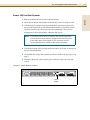
HP Disk System 2120 Desktop
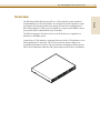
The HP Disk System 2120 Desktop is a high-performance storage solution designed for small businesses and organizations. It offers a range of features and capabilities that can help you improve your data management and storage needs.
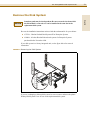
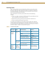
With its hot-swappable disk modules, the HP Disk System 2120 Desktop allows you to easily add or remove disks without powering down the system. This makes it easy to expand your storage capacity or replace failed disks. The system also supports RAID technology, which can help protect your data from loss in the event of a disk failure.
HP Disk System 2120 Desktop
The HP Disk System 2120 Desktop is a high-performance storage solution designed for small businesses and organizations. It offers a range of features and capabilities that can help you improve your data management and storage needs.
With its hot-swappable disk modules, the HP Disk System 2120 Desktop allows you to easily add or remove disks without powering down the system. This makes it easy to expand your storage capacity or replace failed disks. The system also supports RAID technology, which can help protect your data from loss in the event of a disk failure.


-
 1
1
-
 2
2
-
 3
3
-
 4
4
-
 5
5
-
 6
6
-
 7
7
-
 8
8
-
 9
9
-
 10
10
-
 11
11
-
 12
12
-
 13
13
-
 14
14
-
 15
15
-
 16
16
-
 17
17
-
 18
18
-
 19
19
-
 20
20
-
 21
21
-
 22
22
-
 23
23
-
 24
24
-
 25
25
-
 26
26
-
 27
27
-
 28
28
-
 29
29
-
 30
30
-
 31
31
-
 32
32
-
 33
33
-
 34
34
-
 35
35
-
 36
36
-
 37
37
-
 38
38


HP Disk System 2120 Desktop
The HP Disk System 2120 Desktop is a high-performance storage solution designed for small businesses and organizations. It offers a range of features and capabilities that can help you improve your data management and storage needs.
With its hot-swappable disk modules, the HP Disk System 2120 Desktop allows you to easily add or remove disks without powering down the system. This makes it easy to expand your storage capacity or replace failed disks. The system also supports RAID technology, which can help protect your data from loss in the event of a disk failure.
Ask a question and I''ll find the answer in the document
Finding information in a document is now easier with AI
Related papers
-
HP StorageWorks Disk System 2100 (fld rck 0 drvs) User manual
-
-
Hewlett Packard Enterprise H 353 Specification
-
-
HP Computer Drive 1000ux User manual
-
-
-
-
HP HP Smart Array 256MB User manual
-
Hewlett Packard Enterprise AK377A Datasheet
Other documents
-
HP (Hewlett-Packard) 960i User manual
-
Compaq TruCluster Server AA-RHGWC-TE User manual
-
-
-
-
-
-
-
-