Page is loading ...

Second Edition (December 1999)
Part Number: EK–SW2ZS–UA. B01 / 148451-002
Compaq Computer Corporation
Enclosure 4200 Family
LVD Disk Enclosure
User Guide
Part Number: EK–SW2ZS–UA. B01 / 148451-002

Notice
While Compaq Computer Corporation believes the information included in this manual is correct as
of the date of publication, it is subject to change without notice. Compaq makes no representations
that the interconnection of its products in the manner described in this document will not infringe on
existing or future patent rights, nor do the descriptions contained in this document imply the granting
of licenses to make, use, or sell equipment or software in accordance with the description. No
responsibility is assumed for the use or reliability of the firmware on equipment not supplied by
Compaq or its affiliated companies. Possession, use, or copying of the software described in this
documentation is authorized only pursuant to a valid written license from Compaq, an authorized
sublicensor, or the identified licensor.
© 1999 Digital Equipment Corporation.
All rights reserved. Printed in the U.S.A.
Compaq, StorageWorks wordmark, DIGITAL, and StorageWorks
Registered in United States Patent and Trademarks Office and other jurisdictions.
All other trademarks and registered trademarks are the property of their respective owners.
Compaq StorageWorks Enclosure 4200 Family LVD Disk Enclosure User Guide
Second Edition (December 1999)
Part Number: EK–SW2ZS–UA. B01 / 148451-002

Contents
About This Guide
Intended Audience. . . . . . . . . . . . . . . . . . . . . . . . . . . . . . . . . . . . . . . . . . . . . . . . . . . ix
How this Guide is Arranged . . . . . . . . . . . . . . . . . . . . . . . . . . . . . . . . . . . . . . . . . . . ix
Documentation Conventions . . . . . . . . . . . . . . . . . . . . . . . . . . . . . . . . . . . . . . . . . . . xi
Related Documents . . . . . . . . . . . . . . . . . . . . . . . . . . . . . . . . . . . . . . . . . . . . . . . . . xiv
Chapter 1
Introducing the Enclosure
Disk Enclosure Features . . . . . . . . . . . . . . . . . . . . . . . . . . . . . . . . . . . . . . . . . . . . . 1–2
SCSI Buses . . . . . . . . . . . . . . . . . . . . . . . . . . . . . . . . . . . . . . . . . . . . . . . . . . . . 1–3
High Availability . . . . . . . . . . . . . . . . . . . . . . . . . . . . . . . . . . . . . . . . . . . . . . . 1–3
Variable Speed Blowers . . . . . . . . . . . . . . . . . . . . . . . . . . . . . . . . . . . . . . 1–3
Power Supplies . . . . . . . . . . . . . . . . . . . . . . . . . . . . . . . . . . . . . . . . . . . . . 1–4
Data Integrity . . . . . . . . . . . . . . . . . . . . . . . . . . . . . . . . . . . . . . . . . . . . . . . . . . 1–4
Status Monitoring and Display. . . . . . . . . . . . . . . . . . . . . . . . . . . . . . . . . . . . . 1–4
Enclosure Layout. . . . . . . . . . . . . . . . . . . . . . . . . . . . . . . . . . . . . . . . . . . . . . . . . . . 1–4
Major Elements . . . . . . . . . . . . . . . . . . . . . . . . . . . . . . . . . . . . . . . . . . . . . . . . . . . . 1–7
Element Functions . . . . . . . . . . . . . . . . . . . . . . . . . . . . . . . . . . . . . . . . . . . . . . 1–7
Element Replacement. . . . . . . . . . . . . . . . . . . . . . . . . . . . . . . . . . . . . . . . . . . . 1–7
Chapter 2
Starting the Enclosure
Connecting the SCSI Bus Cables . . . . . . . . . . . . . . . . . . . . . . . . . . . . . . . . . . . . . . 2–1
Applying Power. . . . . . . . . . . . . . . . . . . . . . . . . . . . . . . . . . . . . . . . . . . . . . . . . . . . 2–6
Verifying Operation. . . . . . . . . . . . . . . . . . . . . . . . . . . . . . . . . . . . . . . . . . . . . . . . . 2–7
Chapter 3
I/O Modules
Common Features . . . . . . . . . . . . . . . . . . . . . . . . . . . . . . . . . . . . . . . . . . . . . . . . . . 3–2
Configuring the Enclosure SCSI Bus. . . . . . . . . . . . . . . . . . . . . . . . . . . . . . . . 3–2

iv Compaq Enclosure 4200 Family LVD Disk Enclosure User Guide
Module Power Protection. . . . . . . . . . . . . . . . . . . . . . . . . . . . . . . . . . . . . . . . . 3–3
SCSI Bus Termination . . . . . . . . . . . . . . . . . . . . . . . . . . . . . . . . . . . . . . . . . . . 3–3
Status LEDs . . . . . . . . . . . . . . . . . . . . . . . . . . . . . . . . . . . . . . . . . . . . . . . . . . . 3–4
Terminator LED . . . . . . . . . . . . . . . . . . . . . . . . . . . . . . . . . . . . . . . . . . . . 3–4
Power LED . . . . . . . . . . . . . . . . . . . . . . . . . . . . . . . . . . . . . . . . . . . . . . . . 3–4
SCSI Bus Connectors. . . . . . . . . . . . . . . . . . . . . . . . . . . . . . . . . . . . . . . . . . . . 3–4
Replacing an I/O Module. . . . . . . . . . . . . . . . . . . . . . . . . . . . . . . . . . . . . . . . . 3–5
Single-Bus Module . . . . . . . . . . . . . . . . . . . . . . . . . . . . . . . . . . . . . . . . . . . . . . . . . 3–5
Single-Bus I/O Module Status Displays . . . . . . . . . . . . . . . . . . . . . . . . . . . . . 3–6
Single-Bus SCSI Address Maps . . . . . . . . . . . . . . . . . . . . . . . . . . . . . . . . . . . 3–6
Dual-Bus I/O Module . . . . . . . . . . . . . . . . . . . . . . . . . . . . . . . . . . . . . . . . . . . . . . . 3–7
Dual-Bus I/O Module Status Displays. . . . . . . . . . . . . . . . . . . . . . . . . . . . . . . 3–8
Dual-Bus SCSI Address Maps. . . . . . . . . . . . . . . . . . . . . . . . . . . . . . . . . . . . . 3–9
Chapter 4
Environmental Monitoring Unit
Functions . . . . . . . . . . . . . . . . . . . . . . . . . . . . . . . . . . . . . . . . . . . . . . . . . . . . . 4–2
Status LEDs . . . . . . . . . . . . . . . . . . . . . . . . . . . . . . . . . . . . . . . . . . . . . . . . . . . 4–3
Temperature . . . . . . . . . . . . . . . . . . . . . . . . . . . . . . . . . . . . . . . . . . . . . . . . . . . 4–4
Fault Bus . . . . . . . . . . . . . . . . . . . . . . . . . . . . . . . . . . . . . . . . . . . . . . . . . . . . . . . . . 4–4
Enclosure Status Signal . . . . . . . . . . . . . . . . . . . . . . . . . . . . . . . . . . . . . . . . . . 4–4
Device Swap Signal . . . . . . . . . . . . . . . . . . . . . . . . . . . . . . . . . . . . . . . . . . . . . 4–5
Device Fault Signal . . . . . . . . . . . . . . . . . . . . . . . . . . . . . . . . . . . . . . . . . . . . . 4–5
Replacing an EMU . . . . . . . . . . . . . . . . . . . . . . . . . . . . . . . . . . . . . . . . . . . . . . . . . 4–5
Chapter 5
Disk Drives
Status Reporting . . . . . . . . . . . . . . . . . . . . . . . . . . . . . . . . . . . . . . . . . . . . . . . . . . . 5–2
Drive Status. . . . . . . . . . . . . . . . . . . . . . . . . . . . . . . . . . . . . . . . . . . . . . . . . . . . . . . 5–3
Drive Power . . . . . . . . . . . . . . . . . . . . . . . . . . . . . . . . . . . . . . . . . . . . . . . . . . . 5–4
Drive Blank . . . . . . . . . . . . . . . . . . . . . . . . . . . . . . . . . . . . . . . . . . . . . . . . . . . . . . . 5–5
Replacing a Disk . . . . . . . . . . . . . . . . . . . . . . . . . . . . . . . . . . . . . . . . . . . . . . . . . . . 5–6
Chapter 6
Enclosure Power and Cooling
Enclosure Power . . . . . . . . . . . . . . . . . . . . . . . . . . . . . . . . . . . . . . . . . . . . . . . . . . . 6–2
Power Options . . . . . . . . . . . . . . . . . . . . . . . . . . . . . . . . . . . . . . . . . . . . . . . . . 6–2
Temperature Sensing . . . . . . . . . . . . . . . . . . . . . . . . . . . . . . . . . . . . . . . . . . . . 6–3
Blower Interface. . . . . . . . . . . . . . . . . . . . . . . . . . . . . . . . . . . . . . . . . . . . . . . . 6–3
Blowers . . . . . . . . . . . . . . . . . . . . . . . . . . . . . . . . . . . . . . . . . . . . . . . . . . . . . . . . . . 6–3
Status Reporting . . . . . . . . . . . . . . . . . . . . . . . . . . . . . . . . . . . . . . . . . . . . . . . . . . . 6–4

Contents v
Replacing a Power Supply or Blower . . . . . . . . . . . . . . . . . . . . . . . . . . . . . . . . . . . 6–4
Chapter 7
Replacing CRUs
Ordering a CRU. . . . . . . . . . . . . . . . . . . . . . . . . . . . . . . . . . . . . . . . . . . . . . . . . . . . 7–1
ESD Protection . . . . . . . . . . . . . . . . . . . . . . . . . . . . . . . . . . . . . . . . . . . . . . . . . . . . 7–1
Basic Replacement Procedures . . . . . . . . . . . . . . . . . . . . . . . . . . . . . . . . . . . . . . . . 7–2
Initial Installation. . . . . . . . . . . . . . . . . . . . . . . . . . . . . . . . . . . . . . . . . . . . . . . . . . . 7–3
Replacing a Drive . . . . . . . . . . . . . . . . . . . . . . . . . . . . . . . . . . . . . . . . . . . . . . . . . . 7–4
Replacing the Variable Speed Blower. . . . . . . . . . . . . . . . . . . . . . . . . . . . . . . . . . . 7–6
Replacing the EMU . . . . . . . . . . . . . . . . . . . . . . . . . . . . . . . . . . . . . . . . . . . . . . . . . 7–8
Replacing a Power Supply. . . . . . . . . . . . . . . . . . . . . . . . . . . . . . . . . . . . . . . . . . . . 7–9
Replacing the I/O Module . . . . . . . . . . . . . . . . . . . . . . . . . . . . . . . . . . . . . . . . . . . 7–12
Appendix A
Regulatory Notices
FCC Class B Certification . . . . . . . . . . . . . . . . . . . . . . . . . . . . . . . . . . . . . . . . . . . A–1
Country-Specific Certifications. . . . . . . . . . . . . . . . . . . . . . . . . . . . . . . . . . . . . . . A–2
Appendix B
Specifications
Physical Specifications . . . . . . . . . . . . . . . . . . . . . . . . . . . . . . . . . . . . . . . . . . . . . B–1
Environmental Specifications . . . . . . . . . . . . . . . . . . . . . . . . . . . . . . . . . . . . . . . . B–3
Power Specifications . . . . . . . . . . . . . . . . . . . . . . . . . . . . . . . . . . . . . . . . . . . . . . . B–4
Glossary
Index

vi Compaq Enclosure 4200 Family LVD Disk Enclosure User Guide
Figures
Figure 1–1. 14-drive enclosure. . . . . . . . . . . . . . . . . . . . . . . . . . . . . . . . . . . . . . . . 1–1
Figure 1–2. Disk enclosure (rear view) . . . . . . . . . . . . . . . . . . . . . . . . . . . . . . . . . 1–2
Figure 1–3. 14-drive enclosure bays. . . . . . . . . . . . . . . . . . . . . . . . . . . . . . . . . . . . 1–5
Figure 1–4. Enclosure status LEDs . . . . . . . . . . . . . . . . . . . . . . . . . . . . . . . . . . . . 1–6
Figure 1–5. Rear -mounted elements . . . . . . . . . . . . . . . . . . . . . . . . . . . . . . . . . . . 1–6
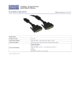
Figure 2–1. Single-bus I/O module cable connector . . . . . . . . . . . . . . . . . . . . . . . 2–2
Figure 2–2. Dual-bus I/O module cable connectors. . . . . . . . . . . . . . . . . . . . . . . . 2–3
Figure 2–3. Typical front status LEDs . . . . . . . . . . . . . . . . . . . . . . . . . . . . . . . . . . 2–7
Figure 2–4. Rear status LEDs. . . . . . . . . . . . . . . . . . . . . . . . . . . . . . . . . . . . . . . . . 2–8
Figure 3–1. Single-bus I/O module . . . . . . . . . . . . . . . . . . . . . . . . . . . . . . . . . . . . 3–1
Figure 3–2. Dual-bus I/O module. . . . . . . . . . . . . . . . . . . . . . . . . . . . . . . . . . . . . . 3–1
Figure 3–3. SCSI Bus A connector symbol . . . . . . . . . . . . . . . . . . . . . . . . . . . . . . 3–4
Figure 3–4. SCSI Bus B connector symbol . . . . . . . . . . . . . . . . . . . . . . . . . . . . . . 3–4
Figure 3–5. Single-bus I/O module components . . . . . . . . . . . . . . . . . . . . . . . . . . 3–5
Figure 3–6. Dual-bus I/O module components. . . . . . . . . . . . . . . . . . . . . . . . . . . . 3–7
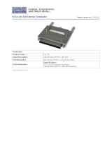
Figure 4–1. Model 4200-series LVD disk enclosure EMU . . . . . . . . . . . . . . . . . . 4–1
Figure 4–2. Model 4200-series LVD disk enclosure EMU location . . . . . . . . . . . 4–2
Figure 4–3. Drive and Enclosure status LEDs . . . . . . . . . . . . . . . . . . . . . . . . . . . . 4–3
Figure 5–1. 1-Inch disk drive . . . . . . . . . . . . . . . . . . . . . . . . . . . . . . . . . . . . . . . . . 5–1
Figure 5–2. Disk drive LEDs display . . . . . . . . . . . . . . . . . . . . . . . . . . . . . . . . . . . 5–2
Figure 5–3. 1-Inch drive blank . . . . . . . . . . . . . . . . . . . . . . . . . . . . . . . . . . . . . . . . 5–5
Figure 6–1. Power supply and blower assembly components . . . . . . . . . . . . . . . . 6–1
Figure 7–1. Typical CRU product label . . . . . . . . . . . . . . . . . . . . . . . . . . . . . . . . . 7–1
Figure A–1. Typical enclosure certification label . . . . . . . . . . . . . . . . . . . . . . . . A–2

Tables vii
Tables
Table 1–1 CRU Replacement Methods . . . . . . . . . . . . . . . . . . . . . . . . . . . . . . . . . . . . 1–8
Table 2–1 Enclosure–Host Controller Maximum Cable Lengths . . . . . . . . . . . . . . . . . 2–3
Table 2–2 Drive Enclosure—Host Controller SCSI Cables . . . . . . . . . . . . . . . . . . . . . 2–4
Table 2–3 Installing SCSI Bus Cables. . . . . . . . . . . . . . . . . . . . . . . . . . . . . . . . . . . . . . 2–6
Table 3–1 Single-Bus Status LED Displays . . . . . . . . . . . . . . . . . . . . . . . . . . . . . . . . . 3–6
Table 3–2 Single Bus SCSI Bus IDs . . . . . . . . . . . . . . . . . . . . . . . . . . . . . . . . . . . . . . . 3–6
Table 3–3 Dual-Bus Status LED Displays . . . . . . . . . . . . . . . . . . . . . . . . . . . . . . . . . . 3–8
Table 3–4 Dual Bus SCSI Bus IDs . . . . . . . . . . . . . . . . . . . . . . . . . . . . . . . . . . . . . . . . 3–9
Table 5–1 Drive LED Status Displays . . . . . . . . . . . . . . . . . . . . . . . . . . . . . . . . . . . . . 5–3
Table 6–1 Power Supply and Blower Status Displays . . . . . . . . . . . . . . . . . . . . . . . . . 6–4
Table 7–1 Common Replacement Procedures . . . . . . . . . . . . . . . . . . . . . . . . . . . . . . . 7–2
Table 7–2 Installing a Drive . . . . . . . . . . . . . . . . . . . . . . . . . . . . . . . . . . . . . . . . . . . . 7–4
Table 7–3 Blower Replacement Procedure . . . . . . . . . . . . . . . . . . . . . . . . . . . . . . . . . 7–6
Table 7–4 EMU Replacement Procedure . . . . . . . . . . . . . . . . . . . . . . . . . . . . . . . . . . . 7–8
Table 7–5 Power Supply Replacement Procedure . . . . . . . . . . . . . . . . . . . . . . . . . . . . 7–9
Table 7–6 I/O Module Replacement Procedure . . . . . . . . . . . . . . . . . . . . . . . . . . . . . 7–12
Table B–1 Disk Enclosure Physical Specification . . . . . . . . . . . . . . . . . . . . . . . . . . . B–2
Table B–2 Element Physical Specifications . . . . . . . . . . . . . . . . . . . . . . . . . . . . . . . . B–2
Table B–3 Operating Specifications . . . . . . . . . . . . . . . . . . . . . . . . . . . . . . . . . . . . . B–3
Table B–4 Shipping or Short Term Storage Specifications. . . . . . . . . . . . . . . . . . . . . B–4
Table B–5 AC and DC Power Specifications . . . . . . . . . . . . . . . . . . . . . . . . . . . . . . . B–4


About This Guide
Intended Audience
This publication is designed for use by Compaq StorageWorks users who are responsible for installing
and maintaining the rack mounted (models 4214R and 4254R) and the tower mounted (models 4214T,
and 4254T) Ultra2 SCSI low voltage differential (LVD) disk enclosures.
How this Guide is Arranged
This manual discusses the product features and operations from the general to the specific. The major
sections of this publication include:
Chapter 1, “Introducing the Enclosure”
This chapter is a description of the LVD disk enclosure features and elements.
Chapter 2, “Starting the Enclosure”
This chapter discusses operating an LVD disk enclosure.
Chapter 3, “I/O Modules”
This chapter discusses the I/O modules functions, operation, and status displays.

x Compaq Enclosure 4200 Family LVD Disk Enclosure User Guide
Chapter 4, “Environmental Monitoring Unit”
This chapter describes the EMU and the high availability fault bus.
Chapter 5, “Disk Drives”
This chapter describes the disk drives, operation, and status reporting.
Chapter 6, “Enclosure Power and Cooling”
The chapter describes the power supply and blower operation and status reporting.
Chapter 7, “Replacing CRUs”
This chapter describes the procedures for replacing customer replaceable units (CRUs).
Appendix A, “Regulatory Notices”
This appendix defines the country-specific regulatory standards for this product.
Appendix B, “Specifications”
This appendix describes the physical, environmental, and electrical specifications of the LVD disk
enclosure and elements.
Glossary
The glossary defines terms common to this product.
Index
An alphabetical reference to major subjects.

About This Guide xi
Documentation Conventions
Table 1 is a list of the documentation conventions and symbols used in this publication.
Table 1 Text Symbols
Text Entries
Boldface type—Boldface type indicates the first instance of terms being defined in the text, the
glossary, or both.
italic type—Italic type indicates one of the following.
■ Emphasis
■ A publication title
■ A glossary cross-reference to another glossary entry.
Special Information
WARNING: Warning contains information essential to people’s safety. It advises
users to take or avoid a specific action could result in physical harm to the user.
CAUTION: A Caution contains information that the user needs to know to avoid
damaging the software or hardware.
IMPORTANT: An important note provides information essential to the completion of a task.
Users can disregard information in a note and still complete a task, but they should not
disregard an important note.
NOTE: A note includes information than emphasizes or supplements important points of the
main text. A note supplies information that may apply only in special cases—for example,
memory limitations, equipment configurations, or details that apply to specific versions of a
program.

xii Compaq Enclosure 4200 Family LVD Disk Enclosure User Guide
Table 2 is a list of the symbols that appear on devices and in this publication.
Status LED Symbols
LED is OFF.
LED is O
N.
LED is F
LASHING
Table 2 Device Symbols
Enclosure Symbols
Enclosure LED label
(Symbol definitions follow.)
Enclosure Status (green)
Enclosure Power (green)
Enclosure Fault (amber)
NOTE: This signal indicates there is an enclosure fault. This does not
indicate that there is possibility of personal injury and is therefore NOT a
WARNING.
Table 1 Text Symbols (Continued)

About This Guide xiii
EMU Symbols
EMU Status LED symbol (green)
I/O Module Symbols
Power Status (ON) LED (green)
Terminator Status LED (green)
SCSI Bus A Connector
Ultra2 SCSI Bus
Input Connector
ISCSI Bus B Connector
Ultra2 SCSI Bus
Input Connector
Drive LED Symbols
Drive Activity LED
Drive Online LED
Drive FAILURE LED
Table 2 Device Symbols (Continued)

xiv Compaq Enclosure 4200 Family LVD Disk Enclosure User Guide
Related Documents
Table 3 lists publications that contain additional information relevant to the LVD disk enclosure
products.
Table 3 Related Publications
Publication Title Part Number
Compaq StorageWorks
Disk Enclosure RETMA Rack Mounting Kit Installation Card
127430-001
Compaq StorageWorks
Disk Enclosure RETMA Rack Mounting Template
102943-001
Hot-Pluggable Wide-Ultra2 SCSI Hard Drives Installation Card
386195-001
Compaq StorageWorks
Replacing a Disk Enclosure Environmental Monitoring Unit Installation Guide
148455-001
Compaq StorageWorks
Replacing a Disk Enclosure Power Supply Installation Guide
148454-001
Compaq StorageWorks
Replacing a Disk Enclosure Ultra2 SCSI I/O Module Installation Guide
148453-001
Compaq StorageWorks
Replacing a Disk Enclosure Variable Speed Fan Installation Guide
148452-001
Compaq StorageWorks
Tower Model 4200T-Series User Guide
122942-001

Chapter 1
Introducing the Enclosure
This chapter describes the StorageWorks Enclosure 4200 family of low voltage
differential (LVD) disk enclosures (see Figure 1–1 and Figure 1–2). These enclosures
support Wide-Ultra and Wide-Ultra2 small computer system interface (SCSI)
protocols. The internal bus supports only LVD drives. The external bus (the enclosure to
the host controller bus) supports either Wide-Ultra2 (LVD) and or Wide-Ultra
single-ended (SE) SCSI protocols. The information in this publication is based on using
the Wide Ultra2 LVD SCSI protocol, the most efficient means of transferring data.
Figure 1–1. 14-drive enclosure
CXO6854A

1–2 Compaq StorageWorks Enclosure 4200 Family LVD Disk Enclosure User Guide
Figure 1–2. Disk enclosure (rear view)
Disk Enclosure Features
The Model 4214- and Model 4254-series enclosures support fourteen, 1-inch, 3.5-inch
form factor hard disk drives or drive blanks. These enclosures are available in either a
rack mountable version (4214R) or in a tower version (4214T). A rack (cabinet) mounted
enclosure requires a RETMA 3U vertical opening (5.25-inches) where a “U” is 1.75
inches.
CAUTION: To ensure proper cooling, all drive bays must have either a drive or drive
blank installed.
The enclosure provides several features, including:
■ Hot-pluggable drives, environmental monitoring unit (EMU), blowers, and power
supplies are replaceable without stopping SCSI bus data transfers.
NOTE: An element with a port colored latch, tab, or handle is hot pluggable.
■
Pluggable I/O module and SCSI bus cables require stopping all data transfers, but do
not require removing power before replacing.
■ Depending upon the host controller, the I/O module is capable of supporting
Wide-Ultra2 SCSI (LVD) or Wide-Ultra SCSI (SE) bus operations.
CXO7082A

Introducing the Enclosure 1–3
These enclosures do not support the following storage devices:
■ Tape drives
■ CD-ROMs
■ Solid state drives
The enclosure has guides that ensure the drives, EMU, I/O module, and power supplies
(the enclosure elements) align and properly mate with the backplane connectors. A
blower guide post on the blower ensures that the blower properly mates with the power
supply. The elements and the metal enclosure provide electromagnetic interference
(EMI) suppression and control air flow within the enclosure.
SCSI Buses
The enclosure supports only Wide-Ultra2 SCSI, wide (16-bit), internal LVD buses.
Depending on the host interface, the external SCSI bus, the bus from the I/O module to the
host can be either Wide-Ultra or Wide-Ultra2, LVD or SE. The SCSI bus type determines
the length of this bus, and therefore, the maximum cable length. The standard Compaq
cable length of 12 ft (3.7 m) ensures satisfactory operation. As for all SCSI buses, the
shorter the cable, the more efficient the bus operation.
NOTE: The maximum bus length is the inverse of the transmission speed. The faster the
transmission rate, the shorter the bus length. For more information about the supported SCSI
bus lengths, see Chapter 3.
Each enclosure has two internal SCSI buses, with half of the devices on each bus. The
single-bus I/O module places all the devices on a single-bus of either 10 or 14 devices. The
dual-bus I/O module maintains two internal buses with either 5 or 7 devices on each bus.
High Availability
The high availability features of the enclosure are a function of the blowers and the power
supplies.
Variable Speed Blowers
All enclosures have two variable speed blowers. In all configurations, the failure of one
blower automatically causes the other blower to operate at a high speed. This ensures that
the failure of a single blower does not disable the enclosure.

1–4 Compaq StorageWorks Enclosure 4200 Family LVD Disk Enclosure User Guide
Power Supplies
In a single power supply configuration, the failure of a power supply disables the
enclosure. Use the optional redundant power supply configuration to prevent this. In this
configuration, the failure of a single power supply or blower does not disable the
enclosure.
Data Integrity
Data integrity could be compromised if data transfers occur when there is no DC power to
the I/O module or the drives, To avoid inducing errors, the power pins on these elements
are longer than the data pins. This ensures that power is always present when a data
transfer occurs.
Status Monitoring and Display
The major status monitoring capabilities of these enclosures include:
■ Displaying the enclosure status on the enclosure LEDs
■ Displaying the element status on the power supply, EMU, drive, and I/O module LEDs
■ Detecting the installation of a blower, power supply, disk drive, or I/O module
■ Detecting the blower removal of a blower, power supply, disk drive, or I/O module
■ Sensing enclosure temperatures
■ Sensing power supply voltage, current, and total power
Enclosure Layout
The physical layout of the enclosure is the same in a rack or a tower. The drives mount in
the bays in the front of the enclosure. These bays are numbered from the left (bay
) to
the right (see Figure 1–5 and Figure 1–3). The common method of referring to a drive is
by the bay number. The drive in bay
is drive 1, the drive in bay is drive 8, and so
forth.
CAUTION: There is no direct correlation between the bay number and SCSI bus ID.
The SCSI bus IDs are a function of the bus type (single or dual) and the number of
drives See Chapter 3 for SCSI bus IDs.

Introducing the Enclosure 1–5
— Drive Bays
— Enclosure Status LEDs
(see Figure 1–4)
Figure 1–3. 14-drive enclosure bays
CXO6728A
1
2
3
4
5
6
7
8
9
10
11
12
13
14
15

1–6 Compaq StorageWorks Enclosure 4200 Family LVD Disk Enclosure User Guide
The enclosure status LEDs are located in the front, lower-right corner of the enclosures
(see
Figure 1–4).
The I/O module, power supplies, blowers, EMU, and cables mount in the rear of the
enclosure (see Figure 1–5).
Enclosure Status (FLASHING)
Enclosure Power (O
N)
Enclosure Fault (O
FF)
Figure 1–4. Enclosure status LEDs
EMU
Blower 1
Power Supply Bay 1, or
Blower Mounting Assembly
1
Blower 2
Power Supply Bay 2
Single- or Dual-Bus I/O
Module
Figure 1–5. Rear -mounted elements
1. In a single power supply configuration, the blower mounts on the blower mounting assembly.
CXO6979A
1
2 3 4 5 6
/