Follett HCD1400R Operation And Service Manual
- Category
- Ice cube makers
- Type
- Operation And Service Manual

HCD1000R, HCD1000N Icemakers
Following installation, please forward this manual
to the appropriate operations person.
Operation and Service Manual
Serial numbers before C19999
Order parts online
www.follettice.com
00129981R06
801 Church Lane • Easton, PA 18040, USA
Toll free (800) 523-9361 • (610) 252-7301
Fax (610) 250-0696 • www.follettice.com

2
Follett Corporation
Equipment Return Policy
Follett equipment may be returned for credit under the following conditions:
1. The equipment is new and unused.
2. A return authorization number has been issued by customer service within 30 days after shipment.
3. Follett receives the equipment at the factory in Easton, PA within 30 days after issuance of the return authorization number.
4. The equipment must be returned in Follett packaging. If the packaging has been damaged or discarded, Follett will forward,
at the customer’s expense, new packaging.
Note: Return freight charges are the responsibility of the customer. If equipment is returned and is damaged because of
improper packaging, Follett Corporation will not be held responsible.
Credit will be issued when:
The equipment has been inspected by Follett and deemed suitable to be returned to stock.
Note: A 15% restocking charge will be deducted from the credit. If the cost to return the product to stock exceeds 15%, the
actual cost will be deducted.

3
Welcome to Follett Corporation
Specications
Operation
Cleaning, weekly exterior care
Cleaning, semi-annual evaporator cleaning
Service
Icemaker operation
Water system
Electrical system
Normal control board operation
Test points
Time delay and self-ushing jumpers
Error faults
Hard errors
Soft errors
Relay output indication
Compressor/refrigerant solenoid output
Wiring diagram, evaporator unit
Wiring diagram, condenser unit
Gearmotor data
Mechanical system
Evaporator disassembly
Evaporator reassembly
Refrigeration system
Condenser unit operation
Refrigerant pressure data
Refrigerant charges
Refrigeration system diagram
Refrigerant replacement requirements
Evacuation
Ambients (evaporator unit)
Ice capacity test
Bin full detection system
Troubleshooting
Replacement parts
Table of contents
4
5
7
7
7
12
12
13
14
14
15
15
15
15
15
16
16
17
18
18
19
19
21
24
24
24
24
25
26
26
26
26
27
28
30

4
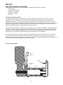
Welcome to Follett
Follett equipment enjoys a well-deserved reputation for excellent performance, long-term reliability and
outstanding after-the-sale support. To ensure that this equipment delivers the same degree of service, we ask
that you review the installation manual (provided as a separate document) before beginning to install the unit.
Our instructions are designed to help you achieve a trouble-free installation. Should you have any questions or
require technical help at any time, please call our technical service group at (800) 523-9361 or (610) 252-7301.
Before you begin
After uncrating and removing all packing material, inspect the equipment for concealed shipping damage. If damage
is found, notify the shipper immediately and contact Follett Corporation so that we can help in the ling of a claim,
if necessary.
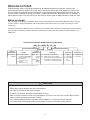
Check your paperwork to determine which model you have. Follett model numbers are designed to provide information
about the type and capacity of Follett equipment. Following is an explanation of the different model numbers in the
1000 series.
CAUTION
• Outdoor installation of low side is not recommended and will void warranty.
• Moving parts. Do not operate with front cover removed.
• Hot parts. Do not operate with cover removed.
• To reduce risk of shock, disconnect power before servicing.
• Most ice machine cleaners contain citric or phosphoric acid, which can cause skin irritation. Read caution
label on product and follow instructions carefully.
• Ice is slippery. Maintain counters and oors around dispenser in a clean and ice-free condition.
• Ice is food. Follow recommended cleaning instructions to maintain cleanliness of delivered ice.
Horizon Series Icemaker Model Number Configurations
A Air-cooled, self-contained
W Water-cooled, self-contained
R Air-cooled, remote condensing unit
N Air-cooled, no condensing unit for
connection to parallel rack system
RVSD 1000HC
HC Horizon
Chewblet
®
D Low side 115/60/1
Condenser 208-230/60/1
(remote condensing only)
C 208-230/60/1
(self-contained only)
E 230/50/1
(self-contained only)
Icemaker
Model Series Voltage
Capacity
Model Series Condenser
V Vision™
H Harmony™
B Ice storage
bin
J Drop-in
1000 up to
1036 lbs
(471kg)
1400 up to
1450 lbs
(658kg)
S Satellite-fill™
T Top-mount
Application Configuration
Chewblet is a registered trademark of Follett Corporation, registered in the US.

5
Specications
Electrical
Separate circuit and equipment ground required.
Evaporator unit
Standard electrical – 115/60/1
Maximum fuse – 15 amps
Amperage – 6 amps
Condenser unit
Standard electrical – 220V, 60Hz, 1 phase
Maximum fuse – 30 amps
Amperage – 17.6 amps
Evaporator plumbing
3/8" OD push-in water inlet
3/4" MPT
Notes: 3/4" vented drain line must slope a minimum of 1/4" per foot (6mm per 30.4cm run).
Drain to be hard piped and insulated.
Water shut-off recommended within 10 feet (3m).
Follett recommends installation of Follett water lter system (part# 00130286) in icemaker
inlet water line.
Ambient
Evaporator unit
Air temperature 100˚F/38˚C max. 50˚F/10˚C min.
Water temperature 90˚F/32˚C max. 45˚F/7˚C min.
Water pressure 70 psi max. (483 kPa) 10 psi min. (69 kPa)
Condenser unit
Air temperature 120˚F/49˚C max.
–
20˚F/-29˚C min.
Refrigeration
3/8" liquid line
5/8" suction line
Note: Rack system installations require a reserve capacity of 7,500 BTU/hr at
2˚F (
–
17˚C) evaporator temperature.
Evaporator pressure regulator (not supplied) is required.
Weight Ice production
Evaporator unit
160 lbs (73kg)
Condenser unit
265 lbs (120kg)
F
C
50
10
60
16
70
21
80
27
90
32
60
16
1101
499
1045
474
990
449
935
424
879
399
70
21
1036
470
980
445
925
420
870
395
814
369
80
27
969
440
913
414
858
389
803
364
747
339
90
32
901
409
845
383
790
358
735
333
679
308
100
38
811
368
755
342
700
318
645
293
589
267
lbs
kg
lbs
kg
lbs
kg
lbs
kg
lbs
kg
Inlet Water Temperature F/C
Ambient Air Temperature F/C
Air-cooled icemaker capacity/24 hrs.

6
Dimensions and clearances
Entire front of icemaker must be clear of obstructions/connections to allow removal.
1" (26mm) clearance above icemaker for service.
1" (26mm) minimum clearance on sides.
Condenser
Side View
Condenser
Front View
26.56"
(675mm)
31.34" (797mm)
22.63"
(575mm)
4"
(102mm)
1.9"
(49mm)
Power connection
Refrigeration
connections
5/8" suction line
3/8" liquid line
2.87
(73mm)
1.81
(46mm)
1.75" (45mm)
min. req'd
NEMA 5-15
right angle
Ice transport hose connection
19.3" (491mm)
3/8" OD push-in water inlet
2.5" (64mm)
15.69" (399mm)
3/4" MPT drain
2.53"
(65mm)
6.95"
(177mm)
15.56"
(395mm)
Front View Side View Back View
21.5" (535mm)
23.5"
(597mm)
21.28" (541mm)
22.8" (58mm)
2
1

7
Operation
Cleaning and preventive maintenance (all models)
Note: Do not use bleach to sanitize or clean the icemaker.
Preventive maintenance
Periodic cleaning of Follett’s icemaker system is required to ensure peak performance and delivery of clean,
sanitary ice. The recommended cleaning procedures that follow should be performed at least as frequently as
recommended, and more often if environmental conditions dictate.
Cleaning of the condenser can usually be performed by facility personnel. Cleaning of the icemaker system,
in most cases, should be performed by your facility’s maintenance staff or a Follett authorized service agent.
Regardless of who performs the cleaning, it is the operator’s responsibility to see that this cleaning is performed
according to the schedule below. Service problems resulting from lack of preventive maintenance will not be
covered under the Follett warranty.
Weekly exterior care
The exterior may be cleaned with a stainless cleaner such as 3M Stainless Steel Cleaner & Polish or equivalent.
Monthly condenser cleaning (air-cooled icemaker only)
1. Use a vacuum cleaner or stiff brush to carefully clean condenser coils of air-cooled icemakers to ensure
optimal performance.
2. When reinstalling counter panels in front of remote icemakers, be sure that ventilation louvers line up with
condenser air duct.
Semi-annual evaporator cleaning (every 6 months)
WARNING
• Wear rubber gloves and safety goggles (and/or face shield) when handling ice machine cleaner or sanitizer.
CAUTION
• Use only Follett approved SafeCLEAN™ Cleaner (part #00132001) and NU-CALGON IMS-II SANITIZER.
• Do not mix Cleaner and Sanitizer solutions together.
• DO NOT USE BLEACH.
• It is a violation of Federal law to use these solutions in a manner inconsistent with their labeling.
• Read and understand all labels printed on packaging before use.
Note: Complete procedure for cleaning an sanitizing MUST be followed. Ice must be collected for 10
minutes before putting ice machine back into service.
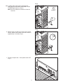
1. To clean – Remove cover. Press the CLEAN
button. The machine will drain. Wait for the LO
WATER light to come on (Fig. 1).
LO WATER
C
L
E
A
N
Fig. 1

8
2. Mix 1 gallon (3.8L) 120˚F (49˚C) water and
7 ounces (198g) (one 7 ounce packet of Follett
SafeCLEAN ice machine cleaner, part#-00132001).
Locate cleaning cup. Fill until HI WATER light
comes on (Fig. 2).
Note: Do not use bleach to sanitize or clean the
icemaker.
3. Replace cover on cleaning cup. Wait until machine
restarts. Machine will clean, then ush 3 times in
approximately 12 minutes (Fig. 3).
4. To sanitize – Press CLEAN button. The machine
will drain. Wait for LO WATER light to come on (Fig.
4).
HI WATER
Fig. 2
12
Fig. 3
LO WATER
N
A
E
L
C
Fig. 4

9
HI WATER
Fig. 5
12
Fig. 6
Fig. 7
5. Mix 1 gallon 120˚F (49˚C) water and 1.6 ounces
(48ml) NU-CALGON IMS-II SANITIZER. Fill until
HI WATER light comes on (Fig. 5).
Note: Do not use bleach to sanitize or clean the
icemaker.
6. Replace cover on cleaning cup. Wait until machine
restarts. Machine will sanitize, then ush 3 times in
approximately 12 minutes (Fig. 6).
7. To clean transport tube – Press power switch OFF
(Fig. 7).

10
Fig. 8
1
2
3
16"
(407mm)
Fig. 9
Fig. 10
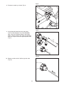
8. Disconnect coupling as shown (Fig. 8).
9. Using disposable food service grade gloves,
insert dry Sani-Sponge
™
(kit part# 00132068).
Next,-insert Sani-Sponge soaked in Nu-Calgon
IMS-II sanitizer solution. Push both Sani-Sponges
down ice transport tube with supplied pusher tube
(Fig. 9).
10. Remove and discard 16" (407mm) pusher tube
(Fig. 10).

11
Fig. 11
Fig. 12
11. Reconnect coupling. Press power switch ON. Ice
pushes Sani-Sponges through tube (Fig. 11).
12. Place a sanitary (2 gallon or larger) container in
bin or dispenser to collect Sani-Sponges and ice
for 10 minutes. Collect 5.5 lbs of ice from unit.
Discard ice and Sani-Sponges (Fig. 12).

12
Service
Icemaker operation (all models)
Follett’s icemaker consists of ve distinct functional systems covered in detail as follows:
• Water system
• Electrical control system
• Mechanical assembly
• Refrigeration system
• Bin full
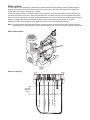
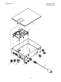
The Horizon icemaker overview
The Follett Horizon icemaker uses a horizontal, cylindrical evaporator to freeze water on its inner surface. The
refrigeration cycle is continuous; there is no batch cycle. The evaporator is ooded with water and the level is
controlled by sensors in a reservoir. A rotating auger (22 RPM) continuously scrapes ice from the inner wall of the
evaporator. The auger moves harvested ice through the evaporator into an ice extrusion canal. The ice is forced
through a restrictive nozzle that squeezes out the water and creates the Chewblet. The continuous extrusion process
pushes the Chewblets through a transport tube into a dispenser or bin.
A solid state PC board controls and monitors the functionality of the ice machine. In addition to sequencing electrical
components, the board monitors various operational parameters. A full complement of indicator lights allows visual
status of the machine's operation. Additionally, the PC board controls the self-ushing feature of the icemaker. The
evaporator water is periodically drained and replenished to remove minerals and sediment.
A unique “bin full” detection system is incorporated in the Horizon icemaker. A switch located at the ice discharge
port of the machine detects the position of the transport tube. When the bin lls up with ice, the transport tube
moves out of the normal running position, and the switch turns the ice maker off. A domed housing at the end of the
transport tube contains the ice extrusion loads during shut down.
water
inlet
auger
compression
nozzle
ice
transport
tube
Harvest system diagram

13
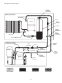
Water system
The water level in the evaporator is controlled by a feed solenoid and level detecting sensors. Referencing the
diagram below, water sensing rods extend down into the reservoir at the end of the evaporator assembly. The
system works via electrical conductivity as follows:
One of the longest probes is a common. When water is between any of the other probes and the common, the
PC board will sense the activation. During normal operation, the water level rises and falls between the Normal
High and Normal Low sensors. As water is consumed to make ice, the level will fall until the Normal Low sensor is
exposed, triggering the water feed solenoid on. Water will ll until the Normal High sensor is activated.
Additional sensors are incorporated in the reservoir for alarm and cleaning/ushing conditions.
Note: The potable water dissolved solids content must be greater than 30 ppm for the water control system to
function properly. If using reverse osmosis water ltration system, ensure T.D.S level is greater than 30 ppm.
Alarm HI
Alarm LO
Normal HI
Common
Normal LO
Normal
operating
range
Water system diagram
Water level diagram

14
Electrical system
Normal control board operation
The PC board indicator lights provide all the information necessary to determine the machine’s status. Green
indicator lights generally represent “go” or normal operation; Yellow indicators represent normal off conditions;
Red indicators generally represent alarm conditions, some of which will lock the machine off.
A green light labeled POWER indicates power to the machine. A ashing green light labeled CPU is normal and
indicates that the Central Processing Unit “heart beat” is working. All other normal operation status indicators are
covered as follows:
1. Ice machine is making ice.
2. Ice machine is not making ice.
3. Ice machine is not making ice.
1. Normal running.
2. Normal time delay. When the bin lls with ice, the LOW BIN
light goes out and the refrigeration and auger drive systems
immediately shut down. The TIME DELAY light comes on,
initiating the time delay period. When the time delay expires,
the machine will restart provided that the LOW BIN light is on.
3. Normal purge indicator. After a selected period of ice
making time has elapsed (2 or 6 hours), the ice machine will
automatically self-ush. The refrigeration system will shut
down but the gear motor will continue to run. After the ush is
complete the machine will rell and start without a time delay.
Ice machine disposition Operating conditions
ON OFF
Legend:
ON or OFF FLASHING
POWER
LOW BIN
AUGER ON
REFRIG ON
PURGE
TIME DELAY
CLEANING
SERVICE
HI AMPS
DRAIN CLOG
HI WATER
CPU
LO WATER
POWER
LOW BIN
AUGER ON
REFRIG ON
PURGE
TIME DELAY
CLEANING
SERVICE
HI AMPS
DRAIN CLOG
HI WATER
CPU
LO WATER
POWER
LOW BIN
AUGER ON
REFRIG ON
PURGE
TIME DELAY
CLEANING
SERVICE
HI AMPS
DRAIN CLOG
HI WATER
CPU
LO WATER

15
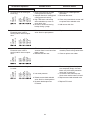
Test points:
The Horizon PC board incorporates on-board test points that can be used to determine various electrical outputs.
The test point holes allow a standard probe to be inserted for quick voltage measurement.
Time delay and self-ushing jumpers:
The duration of the Time Delay period, the time between normal shut down and restart, is jumper selectable.
Jumpers J33 and J34 can be used to select a time delay value of either 1/2, 1, 2, or 3 hours. The factory default
setting is 1 hour. Jumper J32 sets the self-ushing interval to 2 or 6 hours of compressor run time, and J31 either
enables or disables self-ushing feature. The factory default setting is enabled ushing every 2 hours.
Error faults:
The Horizon PC board monitors various operating parameters including auger gearmotor amperage limits,
clogged drain, and high and low water alarm conditions. There are two types of errors namely “hard” or “soft”.
A hard error is one that shuts the machine off and will not allow restart until the reset button is pressed. Even
cycling power will not reset a hard error. A soft error can either be automatically reset should the condition rectify,
or if power is cycled. Should an error occur, consult the troubleshooting guide in this manual or a Follett service
technician. Note: there are two types of LO WATER and HI AMP errors as listed below.
Soft errors:
HI AMPS: The PC board monitors the amperage of the auger motor. Should the gear motor experience current
draw above the 8.4 amps limit the machine will shut down and the TIME DELAY, HI AMP, and SERVICE LED’s
will be illuminated. After the time delay the machine will restart and the TIME DELAY, HI AMP, and SERVICE
LED’s will clear.
HI WATER: A sensor in the water reservoir is positioned at the very top of the reservoir cap. Should water rise to
this high alarm sensor, a soft error will occur. The machine will operate with this alarm active, however the water
feed solenoid will not be on. The alarm will turn off should water recede from the sensor.
LO WATER: During operation, the water level cycles between the normal low and normal high sensors. Should
the water be shut off to a running machine, a soft error will occur. The error sequence is as follows: During
operation, the water level falls to the normal low sensor, and when it does the water feed solenoid is energized. If
water is not detected at the normal low sensor within 120 seconds, a soft error will occur. The machine will shut
down, but the water feed solenoid will remain energized. Should water return, it will ll to the normal low sensor
and the machine will resume normal operation. The error will clear automatically.
Hard errors:
HI AMPS:
1. “Two strikes” feature. If the gearmotor has a second HI AMP occurrence during the countdown period
(6 hours after a HI AMP time delay) a hard error will occur and the HI AMP and SERVICE LED’s will be
illuminated.
2. No current. To prevent the refrigeration system from running without gearmotor rotation the PC board will
indicate HIGH AMP and SERVICE if the drive relay is energized and there is no current draw.
DRAIN CLOG: The drain clog sensor, located in the plastic drain pan behind the drain solenoid, will detect the
presence of water just below the top edge of the pan. If water does not properly ow out of the drain pan it will
rise to the sensor, especially during a self-ushing purge cycle.
LO WATER:
1. There is a sensor in the water reservoir that reaches down to the very bottom. The machine will not start if
water is not present at this sensor.
2. A hard error will occur should water not be present within 60 seconds of power up or if the sensors are
disconnected or damaged.

16
Relay output indication:
Each relay on the board has an indicator light associated with its output. For example, when the relay for the
water feed solenoid is energized, the adjacent indicator light glows green.
Comp/Sol output:
The COMP/SOL output is wired to the liquid line solenoid valve.

17
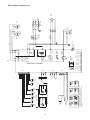
Wiring diagram, evaporator unit
TP3
TP5
TP6
TP8
TP7
TP4
TP11
DRN
H2O
IN
H2O
J15
J14
J13
J16
WATER
INPUT
DRAIN
120Vac
20Watt20Watt
120Vac
FCV-2FCV-1
#32
#33
#30
#31
J8
J12
J11
N
J9
J10
DRV
FAN
SOL
COMP
CB1
#34
#3
#1
#2
M1
J6
K3
CNO
1/2hp Max
J2
J18
J17
SENSING
AMP
MOTOR
J5
J4
J7
L1
NOC
K1
J3
1
2
J34
J33
Time Delay
2 hour
J33
J34
3 hour
Time Delay
J31
J32
J33
J34
SELF FLUSH
TIME DELAY
RESET
SWITCH
JUMPERS
HI WATER (R)
CPU (G)
LO WATER (R)
TIME DELAY (Y)
DRAIN CLOG (R)
LO PRESS (R)
HI PRESS (R)
HI AMPS (R)
SERVICE (R)
CLEANING (Y)
REFRIG ON (G)
AUGER ON (G)
LOW BIN (G)
POWER (G)
PURGE (Y)
J21
CONTROL PC BOARD
J23J22
J24
1
1
1
1
Fluhi
6 hour
J32 J31
(DEFAULT)
(DEFAULT)
FLUSHING
ENABLED
2 hour
Fluhi
(DEFAULT)
J32
Time Delay
1 hour
J34
DISABLED
FLUSHING
J31
J33
Time Delay
J33
1/2 hour
J34
GRAY / GRAY PAIR
RED / GRAY PA IR
J51
4
3
2
1
INPUT 2
OR
MAINT
PURGE
S2
MOM
CLEAN
S3
FULL
BIN
(CONTACT CLOSURE)
RETURN
V
(3 WIRE)
-V
OUT (liht o)
WATER LEVEL
HIGH
ALARM
COM
DRAIN
CLOG
8
LE
7
LE
5
LOW
LE
ALARM
4
LE
COM
3
LE
NORM
HIGH
6
NORM
LOW
2
LE
LE
JUMPER
JUMPER
#22
#24
#23
FCV-3
20Watt
120Vac
REFRIG
J50
3
2
1
00127126R05
D15
D10
D6
D9
D5
Horizon 1000/1400 Series Split System Icemaker
BRN
BLK
BLU
P52
120Vac 60H
L1
GND
N
6Amp DRAW RUNNING
J52
GND
4
1
MAIN OFF/ON
240Vac / 20FLA
O I
S1
#21
#20
5
2
JUMPERS CAN NOT BE REMOVED FROM PC BOARD J31 THRU J34
FORM A SERIES CIRCUIT IF A JUMPER IS REMOVED AND
DISCARDED THE PC BOARD TIMING FUNCTIONS WILL NOT WORK
PROPERLY
801 CHURCH LANE
EASTON PA 18040 USA
800-523-9361 OR 610-252-7301
FOR SERVICE CALL
ON THE WEB olletticecom

18
Gearmotor data
Brother
Gearmotor current 5.0A (nominal)
Locked rotor amps 15 amps
Resistance of windings
115 vac gearmotor (Brother) 1.7Ω
Wiring diagram, condenser unit
1
4
6
5
2
SR
C
S Cap
HP LP
R Cap
L2
L1
Crankcase heater
Dual pressure control
GND
Fan
Orange
Black
Black
Black
Black
Black
Black
Black
Black
Blue
Blue
Blue
Yellow
Red

19
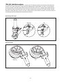
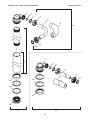
Mechanical system
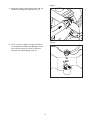
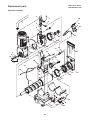
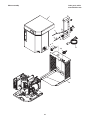
Evaporator disassembly
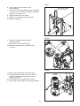
1. Press PURGE button to purge evaporator, and then
turn power OFF.
2. Unscrew and remove stream divider as shown.
3. Unplug and remove gearmotor as shown.
4. Remove all traces of anti-seize compound or petrol-
gel from the auger shaft.
5. Unscrew and disconnect transport tube from
louvered docking assembly.
6. Unplug sensor at the electrical box.
7. Remove vent tube from shuttle housing as shown.
Fig. 13
Fig. 14
Fig. 15

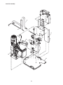
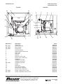
20
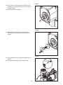
8. Loosen nut on V-band clamp and remove.
9. Remove V-band clamp from front of evaporator.
10. Remove main housing as shown.
11. Remove and discard mating ring and seal.
12. Carefully remove auger.
Fig. 16
Fig. 17
Page is loading ...
Page is loading ...
Page is loading ...
Page is loading ...
Page is loading ...
Page is loading ...
Page is loading ...
Page is loading ...
Page is loading ...
Page is loading ...
Page is loading ...
Page is loading ...
Page is loading ...
Page is loading ...
Page is loading ...
Page is loading ...
Page is loading ...
Page is loading ...
Page is loading ...
Page is loading ...
-
 1
1
-
 2
2
-
 3
3
-
 4
4
-
 5
5
-
 6
6
-
 7
7
-
 8
8
-
 9
9
-
 10
10
-
 11
11
-
 12
12
-
 13
13
-
 14
14
-
 15
15
-
 16
16
-
 17
17
-
 18
18
-
 19
19
-
 20
20
-
 21
21
-
 22
22
-
 23
23
-
 24
24
-
 25
25
-
 26
26
-
 27
27
-
 28
28
-
 29
29
-
 30
30
-
 31
31
-
 32
32
-
 33
33
-
 34
34
-
 35
35
-
 36
36
-
 37
37
-
 38
38
-
 39
39
-
 40
40


Follett HCD1400R Operation And Service Manual
- Category
- Ice cube makers
- Type
- Operation And Service Manual
Ask a question and I''ll find the answer in the document
Finding information in a document is now easier with AI
Related papers
-
Follett HCD1400N Operation And Service Manual
-
-
-
-
-
-
-
-
-
Other documents
-
Manitowoc Ice Q-0130 User manual
-
Scotsman KBILC Basic Ice Level Control Instructions 17-3827-01 Operating instructions
-
Scotsman KBILC Operating instructions
-
 Aqua Free FLUSH 2.0 Operating instructions
-
Global Sources K9 Pro User manual
-
ASI 0363 Installation guide
-
Xing Da Electronics XO-9969 User manual
-
Subaru Robin Power Products R650 User manual
-
Omega FPU2000 and FPUVS2000 Series Owner's manual
