Page is loading ...

Multiparameter signal converter
Electronic Revision: ER 1.1.8
MAC 100
MAC 100MAC 100
MAC 100 Handbook
HandbookHandbook
Handbook
© KROHNE 03/2019 - 4001956903 - MA MAC 100 R03 en
The documentation is only complete when used in combination with the relevant
documentation for the sensor.

All rights reserved. It is prohibited to reproduce this documentation, or any part thereof, without
the prior written authorisation of KROHNE Messtechnik GmbH.
Subject to change without notice.
2
www.krohne.com 03/2019 - 4001956903 - MA MAC 100 R03 en
Copyright 2019 by
KROHNE Messtechnik GmbH - Ludwig-Krohne-Str. 5 - 47058 Duisburg (Germany)
:
IMPRINT
:::::::::::::::::::::::::::::::::::::::

CONTENTS
3
www.krohne.com03/2019 - 4001956903 - MA MAC 100 R03 en
MAC 100
1 Safety instructions 6
1.1 Software history ............................................................................................................... 6
1.2 Intended use ..................................................................................................................... 7
1.3 Certifications .................................................................................................................... 7
1.4 Safety instructions from the manufacturer ..................................................................... 8
1.4.1 Copyright and data protection ................................................................................................ 8
1.4.2 Disclaimer ............................................................................................................................... 8
1.4.3 Product liability and warranty ................................................................................................ 9
1.4.4 Information concerning the documentation........................................................................... 9
1.4.5 Warnings and symbols used................................................................................................. 10
1.5 Safety instructions for the operator............................................................................... 10
2 Device description 11
2.1 Scope of delivery............................................................................................................. 11
2.2 Device description .......................................................................................................... 12
2.3 Sensor input combinations............................................................................................. 14
2.4 Nameplate ...................................................................................................................... 15
3 Installation 16
3.1 General notes on installation ......................................................................................... 16
3.2 Storage and transport .................................................................................................... 16
3.3 Wall mounting ................................................................................................................ 16
4 Electrical connections 20
4.1 Safety instructions.......................................................................................................... 20
4.2 Used abbreviations .........................................................................................................20
4.3 Important device-specific notes on electrical connection............................................. 21
4.4 Opening and closing the converter housing .................................................................. 22
4.4.1 Die-cast aluminium housing................................................................................................. 22
4.4.2 Stainless steel converter housing ........................................................................................22
4.5 Overview of the terminal compartment ......................................................................... 23
4.6 Connecting the signal cables ......................................................................................... 24
4.7 Connecting the power supply......................................................................................... 24
4.8 Description and properties of the outputs and the input............................................... 26
4.8.1 Current output ...................................................................................................................... 26
4.8.2 Relay outputs ........................................................................................................................ 26
4.8.3 Control input (passive) .......................................................................................................... 27
4.9 Connection diagrams of the outputs and the input ....................................................... 28
4.9.1 Important notes..................................................................................................................... 28
4.9.2 Description of electrical symbols ......................................................................................... 28
4.9.3 Block diagram....................................................................................................................... 29
4.9.4 Current output (active).......................................................................................................... 29
4.9.5 Relay outputs ........................................................................................................................ 30
4.9.6 Control input ......................................................................................................................... 30
4.10 Electrical connection of the outputs and the input...................................................... 31
4.10.1 Connecting the current outputs..........................................................................................31

CONTENTS
4
www.krohne.com 03/2019 - 4001956903 - MA MAC 100 R03 en
MAC 100
4.10.2 Connecting the relay outputs.............................................................................................. 32
5 Start-up 35
5.1 Switching on the power .................................................................................................. 35
6 Operation 37
6.1 Operating elements........................................................................................................ 37
6.2 Measuring mode.............................................................................................................38
6.2.1 First measuring page............................................................................................................ 38
6.2.2 Second measuring page ....................................................................................................... 40
6.2.3 Status page ........................................................................................................................... 41
6.2.4 Trend diagram....................................................................................................................... 42
6.3 Menu mode ..................................................................................................................... 42
6.3.1 Navigating through the menus .............................................................................................43
6.3.2 Menu "quick setup"............................................................................................................... 47
6.4 Menu mode structure..................................................................................................... 48
6.5 Function tables ............................................................................................................... 51
6.5.1 Menu A, quick setup.............................................................................................................. 51
6.5.2 Menu B, test .......................................................................................................................... 53
6.5.3 Menu C, setup ....................................................................................................................... 55
6.5.4 Menu D, service..................................................................................................................... 60
6.6 Functions in detail .......................................................................................................... 61
6.6.1 Manual hold........................................................................................................................... 61
6.6.2 Simulation of measured values ............................................................................................61
6.6.3 Status log and calibration log ............................................................................................... 62
6.6.4 Error current of current output............................................................................................ 63
6.6.5 Overflow sign and exponential format.................................................................................. 64
6.6.6 Save settings ......................................................................................................................... 66
6.6.7 Load settings......................................................................................................................... 66
6.6.8 Passwords............................................................................................................................. 67
6.7 Status messages and diagnostic information................................................................ 67
6.7.1 Error category "Device failure" (bold "F") ............................................................................ 69
6.7.2 Error category "Application error" ( "F", not bold) .............................................................. 70
6.7.3 Error category "Out of specification" (S) .............................................................................. 70
6.7.4 Error category "Check request" or "Run check" (C) ............................................................ 71
6.7.5 Error category "Information" (I) ........................................................................................... 71
6.8 Timeout function............................................................................................................. 72
7 Service 73
7.1 Maintenance and repair ................................................................................................. 73
7.2 Spare parts availability...................................................................................................73
7.3 Availability of services .................................................................................................... 73
7.4 Returning the device to the manufacturer..................................................................... 73
7.4.1 General information.............................................................................................................. 73
7.4.2 Form (for copying) to accompany a returned device............................................................ 74
7.5 Disposal .......................................................................................................................... 74

CONTENTS
5
www.krohne.com03/2019 - 4001956903 - MA MAC 100 R03 en
MAC 100
8 Technical data 75
8.1 Measuring principle........................................................................................................75
8.2 Technical data table .......................................................................................................75
8.3 Dimensions and weight .................................................................................................. 79
8.3.1 Housing die-cast aluminium................................................................................................. 79
8.3.2 Housing stainless steel......................................................................................................... 80
8.3.3 Mounting plate die-cast aluminium ..................................................................................... 81
8.3.4 Mounting plate stainless steel.............................................................................................. 82
9 Notes 83

1
SAFETY INSTRUCTIONS
6
MAC 100
www.krohne.com 03/2019 - 4001956903 - MA MAC 100 R03 en
1.1 Software history
The "Electronic Revision" (ER) is consulted to document the revision status of electronic
equipment according to NE 53 for all GDC devices. It is easy to see from the ER whether
troubleshooting or larger changes in the electronic equipment have taken place and how that
has affected the compatibility.
Changes and effect on compatibility
INFORMATION!
In the table below, "x" is a placeholder for possible multi-digit alphanumeric combinations,
depending on the available version.
1Downwards compatible changes and fault repair with no effect on operation (e.g. spelling
mistakes on display)
2-_ Downwards compatible hardware and/or software change of interfaces:
HHART
®
PPROFIBUS
FFoundation Fieldbus
MModbus
Xall interfaces
3-_ Downwards compatible hardware and/or software change of inputs and outputs:
ICurrent output
F, P Frequency / pulse output
SStatus output
CControl input
CI Current input
Xall inputs and outputs
4Downwards compatible changes with new functions
5Incompatible changes, i.e. electronic equipment must be changed.
Release date Electronic Revision Changes and
compatibility
Documentation
2007-12-11 1.0.0 -MA MAC 100 R01
2011-08-18 1.1.0_ 5MA MAC 100 R01
2013-04-11 1.1.1_ 1MA MAC 100 R01
2013-11-05 1.1.2_ 1MA MAC 100 R01
2015-03-31 1.1.5 1MA MAC 100 R01
2015-11-09 1.1.6 1MA MAC 100 R02
2018-04-17 1.1.7 4MA MAC 100 R02
2019-02-01 1.1.8 1MA MAC 100 R03

SAFETY INSTRUCTIONS
1
7
MAC 100
www.krohne.com03/2019 - 4001956903 - MA MAC 100 R03 en
1.2 Intended use
In combination with the different sensors of the OPTISENS series the MAC 100 measures
analytical parameters in water and waste water applications.
1.3 Certifications
The device meets the essential requirements of the EU directives. The CE marking indicates the
conformity of the product with the union legislation applying to the product and providing for CE
marking.
For full information of the EU directives and standards and the approved certifications, please
refer to the EU declaration on the KROHNE website.
Other approvals and standards
•NAMUR recommendation NE 21 and NE 43
DANGER!
Never install or operate the device in potentially explosive areas, it might cause an explosion that
can result in fatal injuries.
INFORMATION!
This device is a Group 1, Class A device as specified within CISPR11:2009. It is intended for use in
industrial environment. There may be potential difficulties in ensuring electromagnetic
compatibility in other environments, due to conducted as well as radiated disturbances.
WARNING!
If the device is not used according to the operating conditions (refer to chapter "Technical data"),
the intended protection could be affected.
CE marking

1
SAFETY INSTRUCTIONS
8
MAC 100
www.krohne.com 03/2019 - 4001956903 - MA MAC 100 R03 en
1.4 Safety instructions from the manufacturer
1.4.1 Copyright and data protection
The contents of this document have been created with great care. Nevertheless, we provide no
guarantee that the contents are correct, complete or up-to-date.
The contents and works in this document are subject to copyright. Contributions from third
parties are identified as such. Reproduction, processing, dissemination and any type of use
beyond what is permitted under copyright requires written authorisation from the respective
author and/or the manufacturer.
The manufacturer tries always to observe the copyrights of others, and to draw on works created
in-house or works in the public domain.
The collection of personal data (such as names, street addresses or e-mail addresses) in the
manufacturer's documents is always on a voluntary basis whenever possible. Whenever
feasible, it is always possible to make use of the offerings and services without providing any
personal data.
We draw your attention to the fact that data transmission over the Internet (e.g. when
communicating by e-mail) may involve gaps in security. It is not possible to protect such data
completely against access by third parties.
We hereby expressly prohibit the use of the contact data published as part of our duty to publish
an imprint for the purpose of sending us any advertising or informational materials that we have
not expressly requested.
1.4.2 Disclaimer
The manufacturer will not be liable for any damage of any kind by using its product, including,
but not limited to direct, indirect or incidental and consequential damages.
This disclaimer does not apply in case the manufacturer has acted on purpose or with gross
negligence. In the event any applicable law does not allow such limitations on implied warranties
or the exclusion of limitation of certain damages, you may, if such law applies to you, not be
subject to some or all of the above disclaimer, exclusions or limitations.
Any product purchased from the manufacturer is warranted in accordance with the relevant
product documentation and our Terms and Conditions of Sale.
The manufacturer reserves the right to alter the content of its documents, including this
disclaimer in any way, at any time, for any reason, without prior notification, and will not be liable
in any way for possible consequences of such changes.

SAFETY INSTRUCTIONS
1
9
MAC 100
www.krohne.com03/2019 - 4001956903 - MA MAC 100 R03 en
1.4.3 Product liability and warranty
The operator shall bear responsibility for the suitability of the device for the specific purpose.
The manufacturer accepts no liability for the consequences of misuse by the operator. Improper
installation or operation of the devices (systems) will cause the warranty to be void. The
respective "Standard Terms and Conditions" which form the basis for the sales contract shall
also apply.
1.4.4 Information concerning the documentation
To prevent any injury to the user or damage to the device it is essential that you read the
information in this document and observe applicable national standards, safety requirements
and accident prevention regulations.
If this document is not in your native language and if you have any problems understanding the
text, we advise you to contact your local office for assistance. The manufacturer can not accept
responsibility for any damage or injury caused by misunderstanding of the information in this
document.
This document is provided to help you establish operating conditions, which will permit safe and
efficient use of this device. Special considerations and precautions are also described in the
document, which appear in the form of icons as shown below.

1
SAFETY INSTRUCTIONS
10
MAC 100
www.krohne.com 03/2019 - 4001956903 - MA MAC 100 R03 en
1.4.5 Warnings and symbols used
Safety warnings are indicated by the following symbols.
• HANDLING
HANDLINGHANDLING
HANDLING
This symbol designates all instructions for actions to be carried out by the operator in the
specified sequence.
iRESULT
RESULTRESULT
RESULT
This symbol refers to all important consequences of the previous actions.
1.5 Safety instructions for the operator
DANGER!
This warning refers to the immediate danger when working with electricity.
DANGER!
This warning refers to the immediate danger of burns caused by heat or hot surfaces.
DANGER!
This warning refers to the immediate danger when using this device in a hazardous atmosphere.
DANGER!
These warnings must be observed without fail. Even partial disregard of this warning can lead to
serious health problems and even death. There is also the risk of seriously damaging the device
or parts of the operator's plant.
WARNING!
Disregarding this safety warning, even if only in part, poses the risk of serious health problems.
There is also the risk of damaging the device or parts of the operator's plant.
CAUTION!
Disregarding these instructions can result in damage to the device or to parts of the operator's
plant.
INFORMATION!
These instructions contain important information for the handling of the device.
LEGAL NOTICE!
This note contains information on statutory directives and standards.
WARNING!
In general, devices from the manufacturer may only be installed, commissioned, operated and
maintained by properly trained and authorized personnel.
This document is provided to help you establish operating conditions, which will permit safe and
efficient use of this device.

DEVICE DESCRIPTION
2
11
MAC 100
www.krohne.com03/2019 - 4001956903 - MA MAC 100 R03 en
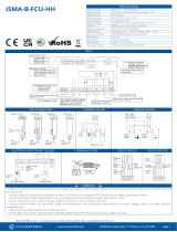
2.1 Scope of delivery
INFORMATION!
Inspect the packaging carefully for damages or signs of rough handling. Report damage to the
carrier and to the local office of the manufacturer.
INFORMATION!
Do a check of the packing list to make sure that you have all the elements given in the order.
INFORMATION!
Look at the device nameplate to ensure that the device is delivered according to your order.
Check for the correct supply voltage printed on the nameplate.
Figure 2-1: Standard scope of delivery
1 Signal converter
2 Product documentation

2
DEVICE DESCRIPTION
12
MAC 100
www.krohne.com 03/2019 - 4001956903 - MA MAC 100 R03 en
2.2 Device description
The signal converter is able to measure different parameters in liquids and fluids which are
common in the water and waste water as well as in food & beverage and the chemical industry. It
has three freely programmable current outputs, one control input and optionally three
mechanical relays which can be configured as alarm or status relays or limit switches.
The manufacturer offers the device as a one channel version and a version with two channels.
The last one possesses two sensor inputs for using sensors with different measuring principles
as they are:
•Amperometric measurements (free chlorine / ozone / chlorine dioxide / dissolved oxygen)
•Potentiometric measurements (pH / ORP)
•Conductivity measurements (conductive / inductive)
•Optical measurements (turbidity /total suspended solids / dissolved oxygen)
When ordering the one channel version, only the interface "Pos.A" is populated. In the version
with two channels the interfaces "Pos.A" and "Pos.B" are populated (for further information
refer to
Overview of the terminal compartment
on page 23).
Figure 2-2: Device description (left - die-cast aluminium / right - stainless steel)
1 Display
2 Operation keys
3 Cable glands
INFORMATION!
•
The configuration of the signal converter (i.e. the number and type of sensor inputs) has to be
set in the factory and cannot be changed later.
•
The number and type of sensor inputs is specified via the order code and visible on the
nameplate.

DEVICE DESCRIPTION
2
13
MAC 100
www.krohne.com03/2019 - 4001956903 - MA MAC 100 R03 en
The manufacturer offers the signal converter as a wall mount version only. Each device has a
passive control input that can trigger an external "out of specification error" (e.g. that there is no
flow). Additionally the control input can help to set the analogue outputs (current outputs and
limit switches) to "zero" or to "manual hold" (e.g. for maintenance). For further details about the
control input please refer to
Control input (passive)
on page 27.
The type and design of the cable glands depend on the version of the converter. For each device
4 cable glands are designated. The material can be selected between plastic or stainless steel.
To connect the conduit systems use a NPT adapter made of brass.
Example for assignment of cable glands
Figure 2-3: Cable glands
1 Power
2 Current output or relay output
3 Current outputs or temperature sensor
4 Sensor input
5 Possibility to connect a functional earth (only relevant for version with 24 V)

2
DEVICE DESCRIPTION
14
MAC 100
www.krohne.com 03/2019 - 4001956903 - MA MAC 100 R03 en
2.3 Sensor input combinations
The following combinations of the OPTISENS sensor inputs are possible:
Possible
combinations
Sensor input A Sensor input B
Single channel
version pH / ORP -
Cl
2
/ ClO
2
/ O
3
-
conductive conductivity -
inductive conductivity -
optical measurement dissolved oxygen -
amperometric measurement dissolved
oxygen -
total suspended solids -
turbidity -
Dual channel
version pH / ORP pH / ORP
pH / ORP conductive conductivity
pH / ORP inductive conductivity
Cl
2
/ ClO
2
/ O
3
pH / ORP
conductive conductivity conductive conductivity
inductive conductivity inductive conductivity

DEVICE DESCRIPTION
2
15
MAC 100
www.krohne.com03/2019 - 4001956903 - MA MAC 100 R03 en
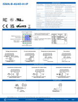
2.4 Nameplate
INFORMATION!
Look at the device nameplate to ensure that the device is delivered according to your order.
Check for the correct supply voltage printed on the nameplate.
1 Manufacturer
2 Device name
3 CE marking
4 TAG number
5 Electronic/electric device waste marking
Observe the operation and installation instruction
Internet address of manufacturer
Data Matrix code (serial number)
6 Power supply data
Number of current outputs
Parameter of measuring unit
7 Order code
Manufacturing date
8 Serial number
Electronic revision
9 Production order

3
INSTALLATION
16
MAC 100
www.krohne.com 03/2019 - 4001956903 - MA MAC 100 R03 en
3.1 General notes on installation
3.2 Storage and transport
3.3 Wall mounting
INFORMATION!
Inspect the packaging carefully for damages or signs of rough handling. Report damage to the
carrier and to the local office of the manufacturer.
INFORMATION!
Do a check of the packing list to make sure that you have all the elements given in the order.
INFORMATION!
Look at the device nameplate to ensure that the device is delivered according to your order.
Check for the correct supply voltage printed on the nameplate.
CAUTION!
Do not make any mechanical modifications to the device. This can result in the loss of proper
functionality, as well as the rights under the device warranty.
•
Store and transport the device in a dry, dust-free environment.
•
Avoid continuous direct sunlight
•
Store and transport the device in an environment with a temperature between -40...+70
°
C /
-40...+158
°
F.
•
The original packing is designed to protect the equipment. It has to be used if the device is
transported or sent back to the manufacturer to prevent damage of the device.
DANGER!
Never install or operate the device in potentially explosive areas, it might cause an explosion that
can result in fatal injuries.
CAUTION!
Always note the following items to ensure a proper and safe installation:
•
Make sure that there is adequate space to the sides.
•
The device must not be heated by radiated heat (e.g. exposure to the sun) to a electronics
housing surface temperature above the maximum permissible ambient temperature. If it is
necessary to prevent damage from heat sources, a heat protection (e.g. sun shade) has to be
installed.
•
Signal converters installed in control cabinets require adequate cooling, e.g. by fan or heat
exchanger.
•
Do not expose the signal converter to intense vibration.
•
Use assembly materials and tools in compliance with the applicable occupational health and
safety directives (assembly materials and tools are not part of the scope of delivery).

INSTALLATION
3
17
MAC 100
www.krohne.com03/2019 - 4001956903 - MA MAC 100 R03 en
The mounting plate is fixed at the back side of the device in the delivery condition. The following
drawings illustrate the proper mounting:
• Note the drawing above and mark all drill holes with the help of a pen, e.g. a felt pen 1.
• Fasten the device securely to the wall with the help of drilling machine, plugs, screws and the
mounting plate 2.
CAUTION!
Installation, assembly, start-up and maintenance may only be performed by appropriately
trained personnel. The regional occupational health and safety directives must always be
observed.
INFORMATION!
A mounting system with a minimum load force of 0.1 kN (for example FISCHER type UX10)
suitable for the background has to be applied.
Wall mounting with plugs
Figure 3-1: Mounting procedure to walls

3
INSTALLATION
18
MAC 100
www.krohne.com 03/2019 - 4001956903 - MA MAC 100 R03 en
Wall mounting of multiple devices (Die-cast aluminium)
Figure 3-2: Dimensions and distances
[mm] ["]
aØ6.5 Ø0.26
b87.2 3.4
c241 9.5
d310 12.2
e257 10.1

INSTALLATION
3
19
MAC 100
www.krohne.com03/2019 - 4001956903 - MA MAC 100 R03 en
Wall mounting of multiple devices (Stainless steel)
Figure 3-3: Dimensions and distances
[mm] [inch]
aØ6.5 Ø0.26
b40 1.6
c268 10.5
d336 13.2
e257 10.1
e

4
ELECTRICAL CONNECTIONS
20
MAC 100
www.krohne.com 03/2019 - 4001956903 - MA MAC 100 R03 en
4.1 Safety instructions
4.2 Used abbreviations
DANGER!
All work on the electrical connections may only be carried out with the power disconnected. Take
note of the voltage data on the nameplate!
DANGER!
Observe the national regulations for electrical installations!
WARNING!
Observe without fail the local occupational health and safety regulations. Any work done on the
electrical components of the measuring device may only be carried out by properly trained
specialists.
INFORMATION!
Look at the device nameplate to ensure that the device is delivered according to your order.
Check for the correct supply voltage printed on the nameplate.
Abbreviation Description
C
p
Control input passive
I
a
Current output active
I
max
Maximum current
I
nom
Nominal current
R
L
Load resistance
R plus number (e.g. R1) Relay contact
PPower
U
ext
External voltage source
U
ext, max
Maximum voltage of the external voltage source
U
int, nom
Nominal internal voltage
U
on
Voltage for triggering the control input (on)
U
off
Voltage for triggering the control input (off)
/