Page is loading ...

1
www.phywe.com, © All rights reserved 13621.00 / 3209
Operating instruct
i
ons
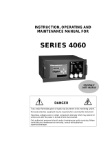
Electrometer Amplifier 13621.00
PHYWE Systeme GmbH & Co. KG
Robert-Bosch-Breite 10
D-37079 Göttingen
Phone +49 (0) 551 604-0
Fax +49 (0) 551 604-107
E-mail info@phywe.de
Internet www.phywe.com
Fig. 1: Front view of the Electrometer Amplifier 13621.00.
The unit complies with
the corresponding EC
guidelines.
1
2
8
5
7
4
6
3
9
CONTENTS
1
SAFETY PRECAUTIONS
2
PURPOSE AND DESCRIPTION
3
FUNCTIONAL AND OPERATING ELEMENTS
4
NOTES ON OPERATION
5
TECHNICAL SPECIFICATIONS
6
MODES OF OPERATION
7
MEASUREMENT PROCEDURES
8
SETS OF EQUIPMENT FOR EXPERIMENTS
WITH THE ELECTROMETER AMPLIFIER:
9
NOTES ON THE GUARANTEE
10
WASTE DISPOSAL
1 SAFETY PRECAUTIONS
• Carefully read these operating instructions completely
before operating this instrument. This is necessary to
avoid damage to it, as well as for user-safety.
• Only use the instrument in dry rooms in which there is no
risk of explosion.
• Only use the instrument for the purpose for which it was
designed.
2 PURPOSE AND DESCRIPTION
Charges that have resulted from static electricity can be
determined by transferring the charge to a capacitor of known
capacitance and measuring the electrical potential of this. It is
difficult to measure this potential with customary measuring
instruments, as a current flows through the measuring
instrument and this leads to decay of the applied charge. The
smaller the internal resistance of the measuring instrument,
the quicker the potential is reduced. Customary measuring
instruments have an internal resistance of about 10 M Ohms.
This electrometer amplifier has it its disposal a voltage input
with a very high internal resistance (> 10
13
Ohms), and can
so be used to measure such charges.
In general, the electrometer amplifier can be implemented to
measure so-called "soft" voltages, i.e. of voltages that break
down with small flows.
For example:
- Potential across a charged capacitor
- Voltage of a weakly lit solar cell
- Voltages that decay at a high ohmic resistance
The electrometer amplifier described here can so be used to
demonstrate many physical effects in electrostatics.
Individual measuring procedures are described in section 7.

2
www.phywe.com, © All rights reserved 13621.00 / 3209
3 FUNCTIONAL AND OPERATING ELEMENTS
1 Amplifier input (high ohmic)
(19 mm socket distance).
2 Auxiliary input
(19 mm socket distance). For attachment of potential
dividers, resistors, capacitors etc..
3 Amplifier output (low ohmic)
For connection of measuring instruments, recorders etc..
4 Trimmer for offset voltage
(See operating notes for adjustment).
5 LED for display of operating voltage
Lights up when an alternating voltage supply (12 V~) is
applied and when Cobra3 Basic-Unit is connected.
6 4 mm Connecting socket
For alternating voltage supply (12 V~) with external
power supplies for example 13505.9X*.
7 Connecting socket for plug-in power supply unit with
hollow plug
Inputs (6) and (7) are connected in parallel.
8 SUB-D socket
For connection to Cobra3 Basic-Unit. No additional
supply voltage is then required.
9 Reference potential (earth)
Caution!
A direct voltage that is not dangerous to touch (< 60 V or a
maximum voltage of 1 kV that is limited to 2 mA) can be
applied at auxiliary socket (2) after appropriate wiring with
potential divider elements. The dimensioning of these
potential divider elements must be so that the ±10 V
permissible voltage at the amplifier input is not exceeded.
Higher voltages can result in the instrument being destroyed.
Further to this, attention must always be paid to sufficient
dielectric strength of the voltage divider elements used.
4 NOTES ON OPERATION
This high-quality instrument fulfils all of the technical
requirements that are compiled in current EC guidelines. The
characteristics of this product qualify it for the CE mark.
This instrument is only to be put into operation under
specialist supervision in a controlled electromagnetic
environment in research, educational and training facilities
(schools, universities, institutes and laboratories).
This means that in such an environment, no mobile phones
etc. are to be used in the immediate vicinity. The individual
connecting leads are each not to be longer than 2 m.
The instrument can be so influenced by electrostatic charges
and other electromagnetic phenomena that it no longer
functions within the given technical specifications. The
following measures reduce or do away with disturbances:
Avoid fitted carpets; ensure potential equalization; carry out
experiments on a conductive, earthed surface, use screened
cables, do not operate high-frequency emitters (radios,
mobile phones) in the immediate vicinity.
When the instrument has been in operation for some time, it
may be necessary to carry out offset matching. To do this,
connect the amplifier input (socket 1) to earth socket (9) and
use offset trimmer (4) and a connected voltmeter to adjust
the output voltage of the amplifier to 0 volts.
5 TECHNICAL SPECIFICATIONS
(Typical for 25°C)
Operating temperature range 5... 40°C
Relative humidity < 80%
Amplification 1.0
Input resistance ≥ 10
13
Ω
Input current ≤ 0.5 pA
Input voltage
Amplifier (socket 1) ±10 V
Auxiliary input (socket 2) 1 kV-
External power supply 12 V~/25 mA
alternatively:
Choice of connection via
Only one power supply 2x4 mm sockets
voltage is to be connected! or hollow plug,
id = 2.1 mm, od = 5.5 mm
or ±15 V via
SUB-D socket to Cobra3.
Output voltage ±10 V (with 12 V~ supply
voltage)
Output 1 mA, short circuit proof
Output resistance ≤ 500 Ω
Dimensions (mm) approx. 65 x 113 x 35
(W, H, D)
Weight approx. 150 g
6 MODES OF OPERATION
6.1 Operation as independent instrument
Accessories required:
Suitable voltage supply, such as:
Power supply 12 V~/500 mA 11074.9X*
Power supply 0 – 12 V-/6 V, 12 V~ 13505.9X*
Power supply , universal 13500.9X*
Cable with 4 mm bunch plug
Output voltage display, for example:
Digital multimeter 07128.00
Analogue demonstration multimeter, ADM 1 13810.00
Analogue demonstration multimeter, ADM 2 13820.00
Cable with 4 mm bunch plug
-------------------------------------------------------------------------
* Voltage and frequency (see type plate) depending on
local power grid
xxxxx.93 = 230 V/50 – 60 Hz
xxxxx.90 = 115 V/50 – 60 Hz
xxxxx.99 = 110 – 240 V/50 – 60 Hz
Special voltages and fixed frequencies on request.

3
www.phywe.com, © All rights reserved 13621.00 / 3209
See section 7 for further accessories as required for
particular measurements.
6.2 Operation with the "Cobra3" computer interface
In this case, the supply voltage required is supplied via the
"Cobra3" computer interface and connecting cable 12150.07.
The output signal is brought to display by the "Universal
recorder" software module 14504.61.
Acessories required for this mode of operation:
Cobra3 Basic-Unit 12150.00
Cobra3 power supply 12151.99
Data cable 2xSUB-D, 9 pin 14602.00
Cobra3 cable for sensors (9/9) 12150.07
Software Cobra3 Universal recorder 14504.61
The requirements of further accessories are dependent on
the measurement to be carried out, and are described in
section 7.
6.3 Operation with the "Cobra4" computer interface
Acessories required for this mode of operation:
Power supply 12 V AC/500 mA 11074.93
Cobra4 Wireless Manager 12600.00
Cobra4 Wireless-Link 12601-00
Cobra4 Sensor-Unit Electricity, 12644.00
current ±6 A / voltage ±30 V
Connecting cord, 32 A, 250 mm, blue 07360.04
Connecting cord, 32 A, 250 mm, red 07360.01
The requirements of further accessories are dependent on
the measurement to be carried out, and are described in
section 7.
7 MEASUREMENT PROCEDURES
7.1 Measurement of charge
Fig. 2: Experimental set-up for the measurement of a charge that is filled into
a Faraday pail by means of a hollow ball coated with graphite.
The charge to be measured is to be given to a capacitor of
known capacitance, e.g. via a Faraday vessel. The potential
that the capacitor has acquired is measured. The amount of
charge present is to be calculated using the relationship:
UCQ ⋅=
; with Q: Charge [Cb]; C: Capacity
V
Cb
and U: Voltage [V]
Schematical experimental set-up
Caution!
Appropriate earthing of the person carrying out the
experiment is necessary here to reduce additional
electrostatic effects. Further to this, the electrometer amplifier
is to be earthed via the available earth connector.
Note:
The capacitance values given on capacitors are nominal
values and may deviate from the actual values. To obtain
exact measurement results, the actual capacitance must be
experimentally determined.
Examples of experiments:
Determination of the capacitance of a spherical capacitor
Apply a voltage of 500 V to charge the hollow ball with
conductive surface. Transfer the charge to a Faraday vessel.
A potential is generated at the 1 nF capacitor. It can be
shown that the charge is transferred in "portions". The
formula for the capacitance "C" of a spherical capacitor can
so be experimentally checked:
rC ⋅=
0
4
πε
, with
m
V
Cb
⋅
⋅=
−12
0
1085,8
ε
; r : spherical radius [m].
Measurement of charge generated by friction
Rub two rods of different materials against each other and
successively dip them into the Faraday vessel. It can be
recognized that the charges generated are opposite. When
only the front parts of the rods are used, it can be shown that
the opposite charges are of the same size.
Recommended accessories:
Faraday pail, d = 40 mm, h = 75 mm 13027.03
(small vessel)
Crocodile clips, bare, 10 pcs 07274.03
Connecting plugs, set of 2 07278.05
alternatively:
Faraday cup 06231.00
(large vessel)
Plug with 3 sockets, red, pack of 2 07206.01
Connecting plug, 4 mm/19 mm 39170.00
(for short-circuiting)

4
www.phywe.com, © All rights reserved 13621.00 / 3209
Support rod with 4 mm hole 02036.01
(for earthing the experimenter)
Capacitor 10 nF, 250 V, 39105.14
in casing G1
Capacitor 1 nF, 100 V 39105.10
in casing G1
Hollow plastic ball 06245.00
(with conductive surface)
Fishing line, d = 0.7 mm, l = 20 m 02089.00
Rod, polypropylene, 13027.07
d = 8 mm, l = 175 mm
Acryl resin rod, d = 8 mm, l = 175 mm 13027.08
Cable with 4 mm bunch plug
7.2 Measurement of direct voltages:
7.2.1 Measurement of direct voltages of up to 10 V
Schematical experimental set-up:
Recommended accessories:
Cable with 4 mm bunch plug
7.2.2 Measurement of direct voltages of more than 10 V
7.2.2.1 High ohmic measurements
Schematical experimental set-up:
Such measurements are based on the following principle:
The applied voltage is divided across an ohmic potential
divider:
21
UUU
e
+=
; with
2
2
1
1
R
U
R
U=
2
2
1
)1( U
R
R
U
e
⋅+=⇒
,
On choosing R1 >> R2, then the following approximation is
valid:
2
2
1
U
R
R
U
e
⋅≈⇒
.
To avoid damage to the instrument, R1 and R2 must be so
chosen that the voltage on amplifier input (1) does not
exceed 10 V, and that the maximum potential between
auxiliary input (2) and the electrometer amplifier earth does
not exceed 1 kV.
Caution!
Ensure that only correspondingly voltage resistant resistors
are used!
Note:
The resistivity values given on resistors are nominal values
and may deviate by up to 5% from the actual values. To
obtain exact measurement results, the actual resistances
must be experimentally determined.
Recommended accessories:
Film resistor 10 GΩ, 5%, 39104.77
in G1 casing
Film resistor 1 GΩ, 5%, 39104.76
n G1 casing
Film resistor 100 MΩ, 5%, 39104.75
n G1 casing
Film resistor 10 MΩ, 5%, 39104.58
n G1 casing
Cable with 4 mm bunch plug
7.2.2.2 Quasi-static measurement
Schematical experimental set-up:
Offset
Power
V
Ua
R
Ua
I
=
Max
±
10V
0V
12V~
0V
R1
R2
Offset
Power
V
±
Uo
Ue
U1
U2
12V~
Offset
Power
V
±
Uo
0V
Ue
C1
C2
U1
U2
12V~

5
www.phywe.com, © All rights reserved 13621.00 / 3209
This measurement is based on the following principle:
The applied voltage is divided across a capacitive potential
divider
21
UUU
e
+=
; with 2211
UCUC ⋅=⋅
2
1
2
)1( U
C
C
U
e
⋅+=⇒
,
On choosing C2 >> C1, then the following approximation is
valid:
2
1
2
)1( U
C
C
U
e
⋅+=⇒
,
To avoid damage to the instrument, C1 and C2 must be so
chosen that the voltage on amplifier input (1) does not
exceed 10 V, and that the maximum potential between
auxiliary input (2) and the electrometer amplifier earth does
not exceed 1 kV.
Caution!
Ensure that only correspondingly voltage resistant capacitors
are used!
Note:
The capacitance values given on capacitors are nominal
values and may deviate from the actual values. To obtain
exact measurement results, the actual capacitance must be
experimentally determined.
Recommended accessories:
Capacitor 0.1 µF, 250 V, 39105.18
in casing G1
Capacitor 10 nF, 250 V, 39105.14
in casing G1
Capacitor 1 nF, 100 V, 39105.10
in casing G1
Capacitor 100 pF, 100 V, 39105.04
in casing G1
Cable with 4 mm bunch plug
7.3 Measurement of small currents
Schematical experimental set-up:
The measurement is based on Ohm's law:
By measuring the decreasing voltage at a known resistance,
the current flowing through the resistor can be calculated.
I = U/R = U
e
/R = U
a
/R
This method is always then used, when small currents are to
be measured with which falsification would occur with a low
ohmic measuring instrument connected in parallel.
Recommended accessory:
Cable with 4 mm bunch plug
8 SETS OF EQUIPMENT FOR EXPERIMENTS
WITH THE ELECTROMETER AMPLIFIER:
Electrometer Amplifier, Set 1 07650.88
This set of equipment for experiments
on measuring charges comprises:
Faraday pail, d = 40 mm, h = 75 mm 13027.03
(small version)
Crocodile clips, bare, 10 pcs 07274.03
Connecting plugs, set of 2 07278.05
Connecting plug (for short-circuiting) 39170.00
4 mm/19 mm, white
Support rod with 4 mm hole 02036.01
(for earthing the experimenter)
Capacitor 1 nF, 100 V, 39105.10
in casing G1
Rod, polypropylene, 13027.07
d = 8 mm, l = 175 mm
Acryl resin rod, d = 8 mm, l = 175 mm 13027.08
Electrometer Amplifier 13621.00
Electrometer Amplifier, Set 2 07651.88
This supplementary set of equipment for
experiments on measuring charges,
voltages and small currents comprises:
Film resistor 10 GW, 5%, 39104.77
in G1 casing
Film resistor 1 GW, 5%, 39104.76
in G1 casing
Film resistor 100 MW, 5%, 39104.75
in G1 casing
Film resistor 10 MW, 5%, 39104.58
in G1 casing
Capacitor 0.1 µF, 250 V, 39105.18
in G1 casing
Capacitor 10 nF, 250 V, 39105.14
in G1 casing
Capacitor 100 pF, 100 V, 39105.04
in G1 casing
Zinc electrode, 76 mm x 40 mm (2x) 45214.00
9 NOTES ON THE GUARANTEE
We guarantee the instrument supplied by us for a period of
24 months within the EU, or for 12 months outside of the EU.
Excepted from the guarantee are damages that result from
Offset
Power
V
R
12V~

6
www.phywe.com, © All rights reserved 13621.00 / 3209
disregarding the Operating Instructions, from improper
handling of the instrument or from natural wear.
The manufacturer can only be held responsible for the
function and technical safety characteristics of the
instrument, when maintenance, repairs and alterations to the
instrument are only carried out by the manufacturer or by
personnel who have been explicitly authorized by him to do
so.
10 WASTE DISPOSAL
The packaging consists predominately of environmentally
compatible materials that can be passed on for disposal by
the local recycling service.
Should you no longer require this product,
do not dispose of it with the household
refuse. Please return it to the address below
for proper waste disposal
.
PHYWE Systeme GmbH & Co. KG
Abteilung Kundendienst (Customer Service)
Robert-Bosch-Breite 10
D-37079 Göttingen
Telephone +49 (0) 551 604-274
Fax +49 (0) 551 604-246
/