Page is loading ...

Pyrometers
METIS M308 / M309 / M313 / M316 / M318 / M323
METIS H309 / H316 / H318
With 12-pin connector, display and push button device configuration
Versions with integrated optics, optical fiber, PID controller, Profibus / Profinet
User Manual

METIS M308 / M309 / M313 / M316 / M318 / M323 / H309 / H316 / H318 (12-pin)
Content
2
Content
1 General ............................................................................................................................................... 4
1.1 Information to this Manual ......................................................................................................... 4
1.2 CE Conformity and Standards .................................................................................................. 4
1.3 Limitation of Liability .................................................................................................................. 4
1.3.1 Devices with PID controller .................................................................................................. 4
1.4 Terms of Warranty .................................................................................................................... 4
1.5 Copyright ................................................................................................................................... 5
1.6 Explanation of Symbols ............................................................................................................ 5
1.7 Customer Service / Spare Parts ............................................................................................... 5
1.8 Disposal .................................................................................................................................... 5
2 Safety .................................................................................................................................................. 6
2.1 General ..................................................................................................................................... 6
2.2 Electrical Connection ................................................................................................................ 6
2.3 Laser Targeting Light ................................................................................................................ 6
2.4 Through-lens Sighting / View Finder ......................................................................................... 6
2.5 Device Labels............................................................................................................................ 6
2.6 Responsibility of the Operators ................................................................................................. 6
3 Overview ............................................................................................................................................ 7
3.1 Intended Use ............................................................................................................................. 7
3.2 Scope of Delivery ...................................................................................................................... 7
3.3 Model Designs .......................................................................................................................... 7
4 Electrical Connection........................................................................................................................ 8
4.1 Cable Colors and Pin Assignment (14-wire connection cables) ............................................... 8
4.1.1 Factory Settings ................................................................................................................... 9
4.1.2 Power Supply ....................................................................................................................... 9
4.1.3 Analog Output 1 and 2 ....................................................................................................... 10
4.1.4 Configurable Inputs / Outputs ............................................................................................ 10
4.1.5 Serial Interface RS232 / RS485 (M3: switchable RS232 / RS485; H3: only RS485) ........ 11
4.1.5.1 Interface Converter (Accessory) ................................................................................... 12
4.1.6 Shielding ............................................................................................................................ 12
4.1.7 Camera Module ................................................................................................................. 12
4.2 Devices with additional Profibus-DP or Profinet connection ................................................... 13
4.2.1 Pin assignment Profibus-DP .............................................................................................. 13
4.2.2 Pin assignment Profinet ..................................................................................................... 13
5 Mechanical Installation ................................................................................................................... 14
5.1 Mounting ................................................................................................................................. 14
5.2 Mounting Optical Fiber / Optics (only devices with optical fiber) ............................................ 14
5.2.1 Bending Radius Optical Fiber ............................................................................................ 14
5.2.2 Winding and Unwinding the Optical Fiber ......................................................................... 14
5.2.3 Mounting of Optical Fiber ................................................................................................... 14
5.2.4 Connect the Optics ............................................................................................................ 15
5.3 Ambient Temperature ............................................................................................................. 15
5.4 Alignment onto the Measuring Object ..................................................................................... 16
5.4.1 Alignment with the Laser Targeting Light .......................................................................... 16
5.4.2 Alignment with the Through Lens Sighting / View Finder .................................................. 17
5.4.3 Alignment with the Camera Module (only M3) ................................................................... 17
5.5 Setting the Measuring / Focus Distance ................................................................................. 18
5.5.1 Manually Focusable Optics ................................................................................................ 18
5.5.2 Motorized Focus Optics (only M3) ..................................................................................... 18
5.5.3 Manually Focusable Fiber Optic Lenses............................................................................ 18
5.5.4 Fixed Focus Optics (only M3) ............................................................................................ 18
5.6 Spot Size Tables ..................................................................................................................... 19
5.6.1 Manually Adjusted or Motorized Focus Optics with laser targeting light or view finder ..... 19
5.6.2 Manually Adjustable or Motorized Focus Optics with camera module .............................. 20
5.6.3 Manually Adjustable or Motorized Focus Optics Model M313 .......................................... 20
5.6.4 Manually Adjusted or Motorized Focus Optics Model M323 ............................................. 21

METIS M308 / M309 / M313 / M316 / M318 / M323 / H309 / H316 / H318 (12-pin)
Content
3
5.6.5 Focusable Fiber-Optic Lenses ........................................................................................... 22
5.6.6 Fixed Focus Optics ............................................................................................................ 22
5.6.7 Calculation of the Spot Size Diameter outside the Focused Distance .............................. 23
6 Configuring the Pyrometer ............................................................................................................. 23
6.1 Displays on the Device ........................................................................................................... 23
6.2 Key Functions ......................................................................................................................... 24
6.3 Parameters / Settings ............................................................................................................. 25
6.3.1 Response Time t90 ............................................................................................................. 26
6.3.1.1 Dynamic Adaptation at Low Signal Levels (only M3 devices) ....................................... 26
6.3.2 Storage Mode Maximum Value Storage (Peak Picker) / Clear Time tCL ........................... 26
6.3.3 Emissivity Ɛ ........................................................................................................................ 26
6.3.4 Transmittance .................................................................................................................... 27
6.3.5 Spot Size Fill Factor ........................................................................................................... 27
6.3.6 Temperature Sub Range ................................................................................................... 28
6.3.7 Temperature Unit ............................................................................................................... 28
6.3.8 Analog Output .................................................................................................................... 28
6.3.9 Test Current ....................................................................................................................... 28
6.3.10 Upscale-Burnout (only via software SensorTools) ............................................................ 28
6.3.11 Customize Analog Output (only via software SensorTools) .............................................. 29
6.3.12 Interface Type (only M3 devices) ...................................................................................... 29
6.3.13 Baud Rate .......................................................................................................................... 29
6.3.14 Address .............................................................................................................................. 29
6.3.15 Interface Delay / Answer Delay) ........................................................................................ 29
6.3.16 Key Lock ............................................................................................................................ 29
7 SensorTools Software .................................................................................................................... 30
7.1 Program Start / Connecting the Pyrometer ............................................................................ 30
7.2 Software Windows .................................................................................................................. 32
7.2.1 Main Window Graphs .................................................................................................... 32
7.2.2 Control Window ................................................................................................................. 35
7.2.3 Device Settings and Configuration .................................................................................... 37
7.2.3.1 Configurable Inputs / Outputs ........................................................................................ 38
7.2.3.2 Service Functions .......................................................................................................... 40
7.2.3.3 Interface ......................................................................................................................... 40
7.2.3.4 Data Collection (Buffer Mode) ....................................................................................... 41
7.2.3.5 Single-Point Adjustment ................................................................................................ 42
7.2.4 PID Controller Equipment .................................................................................................. 44
7.2.5 Profibus- / Profinet Equipment ........................................................................................... 46
7.2.5.1 Fieldbus Mode Selection for Reading the Pyrometer Data ........................................... 46
7.2.5.2 Writing Pyrometer Data ................................................................................................. 48
7.2.6 Setups ................................................................................................................................ 49
7.3 Data Playback ......................................................................................................................... 50
7.4 Communication / Options ....................................................................................................... 51
7.5 Spot Size Calculator ............................................................................................................... 51
8 SensorFlash Software (Update Firmware) .................................................................................... 52
9 Technical Data ................................................................................................................................. 53
9.1 Storage ................................................................................................................................... 54
9.2 Dimensions ............................................................................................................................. 55
9.3 Composition of the Type Number ........................................................................................... 56
9.4 Accessories ............................................................................................................................. 57
10 Maintenance..................................................................................................................................... 58
10.1 Cleaning .................................................................................................................................. 58
10.2 Change Protection Window / Lens at Manual Focusable Optics ........................................... 58
10.3 Pyrometer Calibration ............................................................................................................. 59
10.4 Trouble-Shooting .................................................................................................................... 59
11 Communication via Serial Interface / Interface Commands ....................................................... 59
Index ......................................................................................................................................................... 64

METIS M308 / M309 / M313 / M316 / M318 / M323 / H309 / H316 / H318 (12-pin)
General
4
1 General
1.1 Information to this Manual
This manual is valid for the products listed on the front page, using original parts from Sensortherm.
This manual enables the safe and efficient use with the device. The manual is part of the instrument and
has to be kept in a location where users always have access to.
Read this manual carefully before operating the product. All security notes and operation procedures in
the manuals must be followed to ensure safety.
Additionally the local accident prevention regulations and common safety regulations of the instruments’
operational area are valid.
The descriptions may differ from the current delivery status, since the pyrometer is continuously devel-
oped. Illustrations in this manual are for basic understanding and can differ from the actual construction.
1.2 CE Conformity and Standards
The product conforms to the following standards:
CE conformity: DIN EN 61326-1 (electromagnetic compatibility)
Laser safety: IEC 60825-1, laser class 2 (only devices equipped with laser targeting light)
RoHS: 2011/65/EU
1.3 Limitation of Liability
All information and notes in this manual are made under consideration of valid standards and rules,
state of technology and our expert knowledge for many years.
The producer assume no liability for damages due to:
Non-observance of this manual
Usage out of intended use
Assignment of unskilled personnel
Unauthorized modifications
Technical modifications
Usage of spare parts not approved
The responsibilities of the delivery contract are valid as well as our general terms and conditions and
terms of delivery and the valid statutory rule at date of the conclusion of contract.
1.3.1 Devices with PID controller
The PID controller is designed for temperature control in a variety of applications and has been tested in
these applications over a long period for our satisfaction; especially in fast processes. However, Sensor-
therm doesn’t guarantee that the temperature control meets all the desired requirements over all pro-
cesses. Sensortherm excludes process responsibility.
1.4 Terms of Warranty
A warranty period is 24 months from date of shipment form the Sensortherm facility. The seller will re-
pair or replace the device at its own discretion. Further claims of the buyer against the seller or its
agents are excluded, especially claims for damages that are not incurred in the delivery itself. This shall
not apply in cases of intent, gross negligence, or the absence of assured properties. Damage or misuse
of the product will be determined and void the warranty coverage. Repairs paid by the customer will in-
clude a 180 days warranty from date of shipment. Transportation costs are to be paid by the customer.
Any claims for damage caused by misuse, neglect or tampering with the sensor are excluded.

METIS M308 / M309 / M313 / M316 / M318 / M323 / H309 / H316 / H318 (12-pin)
General
5
1.5 Copyright
This manual is protected by copyrights and are intended solely for internal purposes.
It is not permitted to transfer these instructions to third parties, duplication in any kind and form - includ-
ing excerpts - as well as recovery and / or notification of contents without written permission of the man-
ufacturer, except are internal purposes.
Contraventions are liable for damages. All other rights reserved.
1.6 Explanation of Symbols
The following symbols are used in this manual for restrictions, preventive measures and security notes.
Please pay attention to this symbols for safety reasons.
WARNING!
This combination of symbol and signal word indicates a potentially dangerous situation that
can lead to death or serious injury if not avoided.
CAUTION!
This combination of symbol and signal word indicates a potentially dangerous situation that
can result in minor or moderate injury if not avoided.
CAUTION, LASER RADIATION!
This combination of laser radiation symbol and signal word indicates the dangers of
a laser targeting light.
NOTE:
This combination of symbol and signal word indicates a potentially hazardous situation that
can lead to property and environmental damage if not avoided.
INFO:
This symbol indicates useful tips, recommendations and information for efficient and
trouble free operation.
The identification label on top of the device shows information to:
manufacturer, reference number, temperature range, serial number, serial
interface output (=digital output), analog output, power supply, country of
manufacture and CE sign.
1.7 Customer Service / Spare Parts
For technical information contact our customer service.
It is recommended to purchase spare parts and accessories direct from Sensortherm (manufacturer).
In addition, our employees are always interested in new information and experiences arising from the
application and can be valuable for improvement of our products.
1.8 Disposal
Dispose of the product properly when it is no longer usable: pyrometers include electrical and electronic
waste and have to be recycled or disposed environmentally friendly or to send to the manufacturer for
disposal.
M3
09 07502500058130423-A
Temp. range: 750 - 2500°C
1382 - 4532°F
Serial no: 1234
Digital output: RS 232/485
Made in Analog output: 2x 0/4 - 20 mA
Germany Power: 18 - 30V DC
SensorTherm GmbH

METIS M308 / M309 / M313 / M316 / M318 / M323 / H309 / H316 / H318 (12-pin)
Safety
6
2 Safety
2.1 General
Any person who is tasked to carry out work with the device must have read and understood the oper-
ating manual before beginning.
Operation and maintenance of the system may only be performed by trained personnel.
Save this user manual and hand-over with the device when passed on.
2.2 Electrical Connection
When connecting or when working on the mains voltage, the general safety guidelines are observed,
e.g. when connecting power transformers. Supply voltage can be lethal when touching. Improper instal-
lation can cause serious injury or physical damage. Only qualified personnel are allowed to work with
mains voltage.
2.3 Laser Targeting Light
For easy alignment, the pyrometers may be equipped with a laser targeting light, laser class 2 (accord-
ing to IEC 60825-1-3-4) and has a sticker shown on the right. The laser emits a visible red light with a
maximum power of < 1 mW and a wavelength around 650 nm.
Safety precautions:
Never look into the direct or reflected laser beam.
Do not point the laser to anyone.
If laser radiation hits the eye, the eyes must be intentional-
ly closed and the head immediately moved out of the
beam.
2.4 Through-lens Sighting / View Finder
Devices with through lens sighting and temperature range above 1400°C are equipped with an adjusta-
ble eye protection filter in the eyepiece to reduce glare at high measurement temperatures. The unpro-
tected look at temperatures >1400°C can damage the eyes function permanently.
Safety precaution: before looking toward the high temperatures, always first adjust the eyepiece with
help of a replacement light source by turning onto the darkest area. A safe method is the adjustment by
looking at a lamp.
2.5 Device Labels
On the top of the device there is the type label (nameplate) as well as a warning sticker for devices with
laser targeting light.
The device must be mounted in a manner that the labels after installation are still clearly visible.
Keep the warning signs in always legible condition
Replace damaged labels
2.6 Responsibility of the Operators
If the device is used in the commercial sector the operator is subject to the legal responsibilities for
workplace safety.
In addition to the safety instructions in this manual follow the regulations of safety, accident prevention
and environmental protection.
If the device sholud be integrated into a system, the safety of the system in which the device is integrat-
ed is in the responsibility of the installer of the system.
Laser
beam
direction
Laser warning label
on top of the device

METIS M308 / M309 / M313 / M316 / M318 / M323 / H309 / H316 / H318 (12-pin)
Overview
7
3 Overview
3.1 Intended Use
The pyrometers Metis M3 and H3 are devices for non-contact temperature measurement. With its short-
wave spectral range they are suitable for measurements on metals, ceramics, graphite etc. with tem-
perature ranges depending on the model between 50 and 3300°C (M3) and 120 and 2500°C (H3). The
M3 models have a response time of < 1 ms. The H3 models are high-speed instruments with a re-
sponse time of < 40 µs.
3.2 Scope of Delivery
Pyrometer, software SensorTools, works certificate, user manual
(connection cables are not included in scope of delivery and have to be ordered separately).
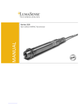
3.3 Model Designs
Standard models:
1
Optics
2
Laser warning label
(only devices with laser targeting light)
3
Device identification label
4
Depending on sighting:
- Eyepiece (models with view finder)
- Laser targeting light push button
- Connector for TV connection
5
Keypad
6
LED display
7
LEDs to indicate system ready or
active switching outputs
8
Connectors for power supply, analog out-
put, serial interface and special functions
9
Mounting rail
10
Mounting thread (M5) for front mounting
the pyrometer or accessory
11
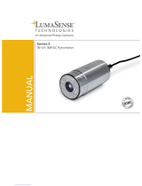
Focusable fiber optics lens
12
Optical fiber for transporting the heat radia-
tion to the pyrometer
13
Tube to protect the optical fiber connection
14
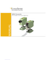
Profibus / Profinet connectors
15
LEDs for monitoring the PB / PN activities
All models feature:
2 linear analog current outputs
A serial interface (M3: RS232 / RS485 switchable; H3: RS485)
3 configurable inputs / outputs
Software SensorTools (included)
Optional sightings: laser targeting light, camera or view finder
Different optics for different measuring distances
Differences in models with fiber optics:
12
11
13
1
10
3
4
5
6
7
8
9
10
2
Additionally at models with Profibus / Profinet:
14
15

METIS M308 / M309 / M313 / M316 / M318 / M323 / H309 / H316 / H318 (12-pin)
Electrical Connection
8
4 Electrical Connection
4.1 Cable Colors and Pin Assignment (14-wire connection cables)
The electrical connection of the pyrometer (supply voltage and measuring signal) will be done via the
connector on the rear panel. For this purpose, pre-assembled connection cables are available as ac-
cessories (see 9.4 Accessories). To prevent accidental short circuits, cable wires not in use should be
secured to the supplied screw terminals.
Cable colors
Sensortherm
pyrometers
No.
Function
Pin
White
1
+ 24 V DC power supply (18–30 V DC)
K
E
DMH
J
L
C
BAK
FG
Connector pins
of the 12 pin
pyrometer connector
(view from outside)
Brown
2
0 V DC power supply (ground)
A
Green
3
+ Analog output 1 (0 / 4–20 mA)
L
Yellow
4
- Analog output 1 (0 / 4–20 mA)
B
White-green
14
+ Analog output 2 (0 / 4–20 mA)
D
Brown-green
15
- Analog output 2 (0 / 4–20 mA)
B
Grey
5
Digital input / output 1 1)
H
Pink
6
Digital input / output 2 1)
J
Blue
13
Digital input / output 3 / Analog input 1)
E
Black
9
RS232: RxD
RS485: B (+) 2)
F
Grey-pink
11
Violet
10
RS232: TxD
RS485: A (-) 2)
C
Red-blue
12
Red
8
DGND (ground for interface)
G
Orange
7
Shield (connect only for cable extension,
do not connect in the control cabinet)
M and plug housing
1) Reference potential 0 V, brown 2) H3 models only RS485
NOTE: In general we recommend the use of the current 14-wire connection cables.
Be careful when using an old 12-wire connector cables (before 2015):
Connection cable for the previous models Metis and Sirius cannot be connected without re-
strictions on a M3 / H3 pyrometer!
Old connection cables are bridged in the cable connector to pins E-C and D-F. Connecting such a ca-
ble to a M3 pyrometer, serial interface and analog output 2 and digital input / output 3 are connected
and the galvanic isolation between the outputs is bypassing. Thereby the pyrometer is not destroyed,
but the functions are no longer available. Using such a cable only analog output 1 is available as output.
Cable colors
old Sensor-
therm cable
Function
Pins
White
Power supply +24 V DC
K
E
DMH
J
L
C
BAK
FG
Connector pins
cable socket (solder side)
Brown
Power supply 0 V DC (ground)
A
Green
+ Analog output (0/4–20 mA)
L
Yellow
- Analog output (0/4–20 mA)
B
Grey
Targeting light, external switch (bridge to K)
H
Pink
Maximum value storage, external clearing (bridge to K)
J
Orange
Screen
M
Red
DGND (Ground for interface)
G
Black
RxD (RS232) or B1 (RS485)
F
Violet
TxD (RS232) or A1 (RS485)
C
Grey / pink
RxD (RS232) or B2 (RS485) (bridge to F)
D
Red / blue
TxD (RS232) or A2 (RS485) (bridge to C)
E

METIS M308 / M309 / M313 / M316 / M318 / M323 / H309 / H316 / H318 (12-pin)
Electrical Connection
9
M3 / H3
0 V
White
Brown
+24 V
Operating
status LED
4.1.1 Factory Settings
Parameters Factory settings
Temperature sub range ........................................ corresponds to basic range
Response time t90 ................................................. Min (corresponds to: M3: <1 ms; H3: <40 µs)
Emissivity ε ........................................................... 1.000 (corresponds to 100%)
Transmittance ....................................................... 100%
Spot size fill factor ................................................. 100%
Serial interface RS232 / 485 ................................. RS485
Data transmission speed (baud rate) .................... 115.2 kBd
Buffer mode .......................................................... Off (at “on”: buffer interval: 100 ms, single reading)
Upscale Burnout function ...................................... Off
Device address ..................................................... 00
Command delay .................................................... 00 (for RS232 and RS485)
Maximum value storage ........................................ Off
Laser targeting switch-off time .............................. 180 s
Analog output 1 ..................................................... 4–20 mA, output temperature: measured temperature
Analog output 2 ..................................................... 4–20 mA, output temperature: no temperature output
Digital input / output 1 ........................................... set to input: external switching on / off targeting light
Digital input / output 2 ........................................... set to input: maximum value storage external clearing
Digital input / output 3 / Analog in ......................... set to input: no function
Input debounce time ....................................... 100 ms
Output activation time .................................... 0 ms
Output hold time ............................................. 10 ms
Limit switch: .................................................... Center of temp. range °C / °F; hysteresis: 10°C / 20°F
Device over temperature: ............................... 50°C / 120°F; hysteresis: 2°C / 5°F
With integrated PID controller:
Analog output 2 ................ 0-20 mA, output set to
control output
Digital input / output 2 ....... Digital input: controller start
Setpoint ............................ Center of temp. range
Proportional band Xp ........ 1%
Derivative time Td ............ 0 ms
Integral time Ti .................. 10 ms
Sampling time ................... 10 ms
Ramp time ............ 0 ms
P-zsc ..................... 100%
P-max ................... 100%
P-min .................... 0%
P-Dyn .................... 100%
AutoTune .............. at each start (power: 50%)
Ramp time ............ 0 ms
Hold time .............. 0 ms
INFO to baud rate: The factory setting of the baud rate is set to 115 kBd to ensure also at
longer interface cables a working data transfer. For data transmissions with the highest speed,
baud rate and buffer mode must be adjusted (see 7.2.3.4)
With integrated Profibus-DP / Profinet:
Field bus mode: ................................ Fixed standard format M3 series
Address ............................................. 126 (delivery address)
4.1.2 Power Supply
With connection to the supply voltage (standard 24 V DC, possible range 18–
30 V) the unit is ready for operation with the factory settings.
By connecting the power supply, the current firmware version is displayed for a
few seconds.
Interrupt the power supply to turn off the pyrometer, e.g. by disconnecting
the connector.
The operating status is displayed on the LED 4:
Orange in the self-test phase (M3 ca. 2 s; H3 during the initialization
and thermostatic phase for ≤ 3 min.)
Green when the pyrometer is ready
Red when an error occurred (see 10.4 Trouble-shooting).

METIS M308 / M309 / M313 / M316 / M318 / M323 / H309 / H316 / H318 (12-pin)
Electrical Connection
10
M3 / H3
0...20 mA
4...20 mA
A
0...20 mA
4...20 mA
A
+IOUT1
-IOUT1
+IOUT2
-IOUT2
Green (+)
Yellow (-)
Brown-green (-)
White-green (+)
Note: The outputs are galvanically
isolated from the supply voltage.
Max. 50 mA
0 V
M3 / H3
Output
+24 V
100 kΩ
White
Grey
Pink
Blue
Brown
0 V
4.1.3 Analog Output 1 and 2
The analog outputs are adjustable (e.g. for a temperature display device):
0–20 mA or 4–20 mA
Analog output 1 always provides the measured temperature
(always the temperature displayed on the device display or the
software control window in SensorTools, see also 7.2.2 Con-
trol window).
(Note: With older firmware versions, the same settings are
possible as at analog output 2. A firmware update to the latest
version eliminates this possibility and prevents, that the output
of analog output 1 is accidentally different to the displayed
temperature signal. Firmware update see section 8).
Analog output 2 can be assigned to provide different signals:
- Measured temperature (always the temperature selected and displayed on the device display and
the software control window; also see 7.2 and 7.2.2 in SensorTools).
- Device temperature
- Manipulated variable of the controller output (when equipped with PID controller).
4.1.4 Configurable Inputs / Outputs
3 ports are each available as:
Digital output: output of a switching signal (invertible, see under
7.2.3 Various settings Logic NO / NC) at:
- Limit switch when a certain temperature threshold is exceed-
ed or falling below
- Material detection (only M3): turns on when exceeding the
beginning of temperature range
- Device ready to operate (device ready and error-free after self-test)
- Exceeding the maximum allowed internal device temperature
- Controller activity (only when equipped with PID controller)
Digital input: A voltage pulse of 24 V (exception: continuous voltage at "Activate controller"), pulse
length adjustable via software (minimum 3 ms,
factory settings 100 ms) under 7.2.3 Configu-
rable Inputs / Outputs debounce time ena-
bles:
- Clear of maximum value storage (see 6.3.2)
- Start controller (when equipped with PID con-
troller, see 7.2.4).
- Activate controller: The control process is ac-
tivated as long as voltage at the terminal is pre-
sent.
- Load pyrometer configuration (devices with PID controller also control parameters) (see under
7.2.3 Configurable Inputs / Outputs “parameter selector” or 7.2.5 Setups).
- Switch on / off laser targeting light (when equipped with laser targeting light)
(the targeting light will automatically switched off after 3 minutes if it is not switched off manually.
Adjustable via software under 7.2.3 Device Settings Laser targeting light settings).
CAUTION, Laser Radiation, Laser Class 2:
Never look into the direct or reflected laser beam.
Do not point the laser to anyone.
If laser radiation hits the eye, the eyes must be intentionally closed and the head
immediately moved out of the beam.
M3 / H3
>10 kOhm
0 V
+24 V
Input 1-3
Push
button
0 V
+24 V
White
Grey
Pink
Blue
Brown

METIS M308 / M309 / M313 / M316 / M318 / M323 / H309 / H316 / H318 (12-pin)
Electrical Connection
11
Analog input (only M3): About a 0–20 mA current source (e.g.
via a setpoint generator), some parameters can be adjusted ex-
ternally between their smallest and largest setting value (settings
via SensorTools software Configurable Inputs / Outputs
Analog input):
- Emissivity (0 mA = 0.05; 20 mA = 1.2)
- Setpoint at devices with PID controller (0 mA = zero scale
temperature, 20 mA = full scale temperature)
- Measuring distance at M3 devices with motorized focus (0 mA = shortest distance, 20 mA = wid-
est distance)
4.1.5 Serial Interface RS232 / RS485 (M3: switchable RS232 / RS485; H3: only RS485)
The serial interface is used for digital communication of the pyrometer with another computer, for exam-
ple a PC for data transmission to the software SensorTools.
The maximum transmission speed (in Baud) is limited by the cable length; it is halved with each dou-
bling of the transmission path.
RS232: about 7 m cable length with 19.2 kBd. Adjustable are values from 4.8 to 115.2 kBd.
RS485: about 2 km with 19.2 kBd. Adjustable are values between 4.8 and 921.6 kBd.
Connecting one pyrometer via
RS232 or RS485:
In a short RS232 or RS485 connection to the mas-
ter (computer receiving the data), the pyrometer is
connected directly as a point-to-point connection
with the master.
It is advantageous to connect all interface cables
in order to avoid reflections.
Connecting several pyrometers via RS485:
For a reflection-free operation with longer cables,
pay attention to the correct cable termination. Termination at the physical bus is on front and rear.
Master at the
beginning:
Master in the
middle:
When operating multiple devices (up to 32 are possible), each device needs to assign its own address
(directly on the device or via software SensorTools), under which it can be addressed later. For this
purpose, initially, each device must be connected individually and provided with an address (00-97). Af-
ter that, all devices can be connected.
If specific parameters for all devices should be changed simultaneously, the global address 98 is used
(there is no response from the device). If the address of a device is unknown, you have the opportunity
to address each device independently of the set address with the global address 99 (connect only one
device).
Master
A (-)
B (+)
DGND
120 Ω
... Pyrometer n
Terminating
resistor 120 Ω
Pyrometer 2
Pyrometer 1
Terminating
resistor 120 Ω
in the master
or manually
A
B
GND
A
B
GND
A
B
GND
A
B
GND
B
A
B
A
120 Ω
... Pyrometer n
Terminating
resistor 120 Ω
Pyrometer 1
A
B
GND
B
A
B
A
120 Ω
Master
A (-)
B (+)
DGND
A
B
GND
Terminating
resistor 120 Ω
GND
RxD
TxD
GND
Pin 2
Pin 3
Pin 5
A (-)
B (+)
GND
RS485
(Master /
PC)
A (-) Red-blue
B (+) Black
B (+) Grey-pink
A (-) Violet
DGND Red
TxD Red-blue
RxD Black
RxD Grey-pink
TxD Violet
DGND Red
RS232 (PC)
Pyrometer
Pyrometer
Setpoint input
via external
0...20 mA
0 V
Current source
M3
Blue
Brown
≤300 Ω

METIS M308 / M309 / M313 / M316 / M318 / M323 / H309 / H316 / H318 (12-pin)
Electrical Connection
12
4.1.5.1 Interface Converter (Accessory)
A quick and easy way to connect the
pyrometer with a PC is to use an inter-
face converter or a connecting cable
with integrated interface converter (see
9.4 Accessories). Depending on the
operating system, suitable drivers are
installed automatically or can be found
on the CD supplied with the software
SensorTools in the directory Drivers FTDI_USB_COM, or after installing SensorTools in the installa-
tion directory (updated driver for Windows from the FTDI website:
http://www.ftdichip.com/Drivers/VCP.htm).
To achieve the maximum transfer speed, it is absolutely necessary to change the latency time in the
advanced connection settings from 16 ms to 1 ms (settings in the Control Panel device manager
Ports (COM & LPT) USB Serial Port Port Settings Advanced Latency Timer (at BM options)).
More information is available in the FTDI application note AN_107 - Advanced Driver Options.
4.1.6 Shielding
Orange: To meet the requirements for electromagnetic compatibility (EMC), only shielded cables
should be used. The shield of our connection cable is connected to the pyrometer side in the plug hous-
ing, on side of the connecting wires (voltage source) it remains open to prevent ground loops.
4.1.7 Camera Module
Devices with camera module as alignment are
equipped with an additional connector at the
rear (Lemo connector) for the output of the
camera signal (standard FBAS signal). Cable
see 9.4 Accessories.
cable connector: type FE.0S.302.CLAC50
Fa. Lemosa GmbH, http://www.lemo.de)
Pin
Output
1
FBAS signal
2
Ground
Cable colors
Metis M3 / H3
Cable colors
interface converter
RS232USB (TxD / RxD)
RS485USB (A‾ / B+)
Red (GND)
Black (GND)
Grey-pink / black (B+ / RxD)
Orange (B+ / TxD)
Red-blue / violet (A‾ / TxD)
Yellow (A‾ / RxD)
2
1

METIS M308 / M309 / M313 / M316 / M318 / M323 / H309 / H316 / H318 (12-pin)
Electrical Connection
13
4.2 Devices with additional Profibus-DP or Profinet connection
The Profibus or Profinet interface is used for the digital communication of one or more pyrometers with
a PLC. It is available in addition to the serial RS232 or RS485 interface.
The connection is made in accordance with the applicable bus specifications.
The maximum possible transmission speed is limited by the cable length:
Profibus: 9.6–93.75kb/s 1200 m up to 3-12Mb/s 100m
Profinet: According to Ethernet standard (Cat5 / Cat6 cable) 100 m
INFO for setting the data to be transmitted: 3 different transmission modes are available to
receive the data packets. A fixed M3 standard mode (factory setting), a backward compatible to
old Metis devices and a variable format in which the data to be transmitted can be selected.
The modes can be selected on the device menu or via SensorTools software. The variable for-
mat must be configured via SensorTools (settings under Device configuration Field bus
mode, also see 7.2.5).
For the typical connection in succession, there
are 2 connections on each device as input and
output.
General Station Discription (GSD): The en-
closed CD contains a device description file that
must be integrated into the configuration of the master (PLC).
Profibus devices: SENSORTHERM_HMSA1815.gsd
Profinet devices (for mode 0 or mode 1 and 2 each in one folder on the CD):
GSDML-V2.32-HMS Industrial Networks-Anybus CompactCom 40 PIR-20180424.xml
INFO about the GSD file of old Metis Profibus devices: If old Metis devices are replaced by
new Metis 3 devices, the correct GSD file must also be included.
4.2.1 Pin assignment Profibus-DP
Profibus terminating resistor: If no
other Profibus device is connected to
the output, the output must be termi-
nated with resistors. The terminating
resistor plug AK81 is used for this pur-
pose (accessory, see 9.4). The internal
wiring is shown on the right.
4.2.2 Pin assignment Profinet
1) TD+
3) RD+
6) RD-
1
2
3
4
5
6
7
8
2) TD-
RJ45 plug
M12 female
connectors,
8-pin
2) TDB-
3) RDB+
4) RDB-
1) TDB+
1) TDA+
2) TDA-
3) RDA+
4) RDA-
4) Profibus cable B (red)
3+1) Not used
5) Schirm
2) Profibus cable A (green)
Input Profibus
Output Profibus
4) Profibus cable B (red)
3) GND Bus
5) Shield
2) Profibus cable A (green)
1) +5 V Bus
M12 connector, M12-female
connector,
5-pin
Profibus-DP
(Slave)
Input
Output
Profinet
Input / output
+5 V (Pin 1)
A (Pin 2)
B (Pin 4)
GND (Pin 3)
Terminating resistor AK81
(internal wiring)
390
220
each 0.25 W
390

METIS M308 / M309 / M313 / M316 / M318 / M323 / H309 / H316 / H318 (12-pin)
Mechanical Installation
14
5 Mechanical Installation
5.1 Mounting
The mounting rail on the bottom case is for the stable take-up of for ex-
ample of a ball and socket mounting (for fiber optics devices a mounting
angle is recommended, see 9.4 Accessories)
Front M5 threaded holes can also be used for mounting (all 4 threads
has to be used for fixing).
The slightest deviation from the optical axis is achieved with the optics
adapter/holder of motor focus and fixed focus devices.
Note that the installation of the pyrometer is free of vibrations, if neces-
sary, helps the use of rubber absorbers when mounting.
To keep the optical fiber ready for use as long as possible, it should be
exposed as little as possible to permanent movement and mechanical
stress. Lay the optical fiber as possible with a large bending radius, especially if it is carried along
moving parts.
During installation of the optical fiber, it is advisable that both plug ends are not yet connected to the
pyrometer and the optics. Tensile and torsional stresses are to be avoided.
INFO: Through manufacturing tolerances the optical and mechanical axis are not running 100%
in the same direction. The pyrometer should be realigned if it is installed again and twisted in
the same holder (see 5.4 Alignment onto the measuring object).
5.2 Mounting Optical Fiber / Optics (only devices with optical fiber)
5.2.1 Bending Radius Optical Fiber
The color code on the optical fiber identi-
fies the optic diameter and minimum bend-
ing radius associated.
When laying the optical fiber it is to ob-
serve the minimum bending radius. A
bending radius smaller than the specified
can cause a stretched or broken optical fiber.
5.2.2 Winding and Unwinding the Optical Fiber
During winding and unwinding the optical fiber must be able to move easily
and should not be twisted. Ideally, one hand winds up the light guide careful-
ly, while the other hand guides the cable roll. For torsion-free winding only
one side of the optical fiber should be connected, than the other can be
moved freely.
NOTE: Strong tensile and torsional forces during rolling and
mounting should be avoided.
5.2.3 Mounting of Optical Fiber
Assignment fiber to pyrometer and optics: Each fiber is uniquely associated to a pyrometer and op-
tics. For identification, all three components are tagged with the same device number. The measure-
ment accuracy can on-
ly be guaranteed with
proper assignment.
Color mark
of the optical fiber
Fiber diameter
Minimum
bending radius
Blue
0.4 mm
150 mm
Red
0.2 mm
75 mm
White
0.1 mm
38 mm
Expl.: Metis with swivel
mounting base, cooling
plate and air purge

METIS M308 / M309 / M313 / M316 / M318 / M323 / H309 / H316 / H318 (12-pin)
Mechanical Installation
15
INFO: To meet the high accuracy, the instrument should be recalibrated when replacing an
optics or or the fiber optic cable.
NOTE: To prevent the ingress of dirt, remove the protective caps from the pyrometer and op-
tics and fiber just before installation.
Keep the protective caps to be able to protect against dirt in any subsequent dismantling or
storage.
The optical fiber has to be mounted true-sided:
The colored heat shrink tube marker matches to the
pyrometer side.
The optics fit on the side without marking
Unscrew the optical fiber protective tube from the py-
rometer’s housing
Pull the protective tube somewhat about the optical fi-
ber on the colored side to avoid pulling it over the
complete fiber after fiber assembly.
Remove the protective caps from the pyrometer and
optical fiber, insert the side with the turn protected fiber
connector to the pyrometer, and make sure that pin and
recess snap together.
Tighten lock nut hand-tight (do not use a tool, otherwise
the screw or optical fiber can be damaged).
Finally screw the protective tube back on the pyrometer
housing.
5.2.4 Connect the Optics
Remove the protective caps from optical fiber and
optics
The fiber-optic connectors on the side of the optics
does not require special adjustment and is just
plugged and screwed
Tighten lock nut hand-tight (do not use a tool, other-
wise the screw or optical fiber can be damaged).
5.3 Ambient Temperature
M308, M309 and M316 are designed for ambient temperatures between 0 and 80°C
M318 models should only be used up to 60°C to maintain measurement accuracy
M323 is designed for ambient temperatures up to 70°C
H3 models are permissible up to maximum 65°C.
Fiber optic devices can be exposed on optics and optical fiber to ambient temperatures between -20
and 250°C without cooling, for the housing the same temperatures apply as for standard devices.
Color mark
Connector pyrometer’s side
(turn-protected)
Ambient temperature on
pyrometer’s side max. 100°C
Ambient temperature on
optics side max. 250°C
Connector optics side
Recess
Pin
Lock nut
Opt. fiber
Protective tube
Color mark

METIS M308 / M309 / M313 / M316 / M318 / M323 / H309 / H316 / H318 (12-pin)
Mechanical Installation
16
INFO to avoid overheating of the laser targeting light or camera module:
The laser targeting light is deactivated at an internal device temperature above 65°C (M3 de-
vices) or above 60°C (H3 devices).
The camera module is deactivated at an internal device temperature above 55°C.
Below that temperatures the sighting can be used again.
Operation outside this temperature leads to incorrect measurements and may damage the device.
To comply with the permitted ambient temperature sufficient distance from the (hot) measuring object is
to observe.
The internal housing temperature can be read out via the soft-
ware SensorTools (see 7).
It is possible to configure one of the switching outputs so that a
corresponding signal is switched when the maximum tempera-
ture is exceeded (see 4.1.4 Configurable Inputs / Outputs and under 7.2.3.1 Configurable In-
puts / Outputs).
Accessory: With radiant heat from the front, the pyrometer can be protected by a cooling plate. The
use of the pyrometer in ambient temperatures outside the permissible pyrometer’s ambient temperature
is possible with an additional cooling housing.
5.4 Alignment onto the Measuring Object
To detect the temperature correctly, the pyrometer
must be aligned properly to the measuring object. In
the focus point of the optics (focused distance) the
spot size diameter is the smallest. Also measurements
in the defocused area can be done to determine the
average temperature of a bigger spot. If the target un-
der measurement is smaller than the spot size pro-
duced by the lens, the colder or warmer border is also
measured and results in a lower or higher temperature
To get a correct measurement result, the following requirements must be observed:
The optical path between pyrometer and the target must be free of interfering objects and vapors,
fumes or dust (if necessary, use air purge or sight tube, see 9.4 Accessories).
A viewing window between pyrometer and the measured object must have constant transmission
properties in the spectral range of the pyrometer (e.g. quartz glass or BK7 crown glass).
The distance to the measured object must be in the range of focusable measurement distance of the
optics, if a precise measurement is to be made.
If the target is smaller than the spot size, there will be
measuring errors because background temperatures
go with the measurement.
If the target is smaller than the spot size, there will be
measuring errors because background temperatures
influence the measurement. If the target is smaller
than the spot size and the background temperature is
cold, a fill factor can be entered that specifies what
percentage is filled in the measuring field (input see 6,
Configure the Pyrometer and 7 SensorTools Software 7.2.2 Control window).
5.4.1 Alignment with the Laser Targeting Light
The laser targeting light is a conical red laser beam
with the largest diameter directly at the lens and the
smallest and sharpest in the focused distance, i.e. at
the point where the measuring field is the smallest
(= Measuring distance in the spot size tables).
Focus point
Spot size and
laser point bigger
DT: internal de-
vice temperature
via software
Spot size smaller than meas-
ured object, measurement OK
Measuring object
Spot size larger than measured
object, enter fill factor, observe
background radiation!
Focus point
Spot size bigger

METIS M308 / M309 / M313 / M316 / M318 / M323 / H309 / H316 / H318 (12-pin)
Mechanical Installation
17
INFO to the spot size: The size of the laser point does not match to the spot size, spot sizes
are given in the spot size tables (see 5.6).
CAUTION, Laser Radiation, Laser Class 2:
Never look into the direct or reflected laser beam.
Do not point the laser to anyone.
If laser radiation hits the eye, the eyes must be intentionally closed and the head immedi-
ately moved out of the beam.
Turn on / off: Via the targeting light button on rear panel or via software
SensorTools (see 7.2.2 Control window).
(the targeting light will automatically switched off after 3 minutes if it is not
switched off manually. Adjustable via software under 7.2.3 Device Set-
tings Laser targeting light settings).
INFO: The laser targeting light is turned off at a device tem-
perature above 65°C (M3 devices) or 60°C (H3 devices)
If the targeting light does not turn on, probably the device's inter-
nal temperature is too high. In this case, the place of installation
of the pyrometer should be checked (excessive heat radiated
from the measuring object). If the temperature falls below the
switch-off value, the laser will work again.
5.4.2 Alignment with the Through Lens Sighting / View Finder
The view finder provides upright imagery so that the target under
measurement can be viewed visually. A target circle shows the
measuring spot when the target is in focus.
Devices with temperature range above 1400°C are equipped with a
continuously adjustable eye protection filter in the eyepiece to reduce
glare at high measurement temperatures. Rotating the eyepiece will
change the brightness.
INFO: The size of the target circle does not match to the spot
size, spot sizes are given in the spot size tables (see 5.6).
CAUTION, Danger of eye damage at measuring temperatures above 1400°C!
To protect the eyes at high measuring temperatures, first, before alignment, the eyepiece
must be adjusted to the darkest position, a safe method is the adjustment by looking at a
replacement light source, e.g. a lamp.
5.4.3 Alignment with the Camera Module (only M3)
Pyrometers with a color camera module provide
a composite video output that can be connected
to a TV or monitor or PC via converter. The py-
rometer is focused and aligned via a target cir-
cle on the TV screen.
About the field of view of approximately 3.6% x
2.7% of the measured distance also the meas-
urement events can be observed. About the PC
software, image overlays and camera settings can be configured (see under 7.2.2 Control window
camera settings).
INFO about the target circle size: The size of the target circle does not match to the spot size,
spot sizes are given in the spot size tables (see 5.6).
Laser targeting
light button
Software
View finder
TV connector

METIS M308 / M309 / M313 / M316 / M318 / M323 / H309 / H316 / H318 (12-pin)
Mechanical Installation
18
INFO: The camera module is turned off at a device temperature above 55°C.
If the camera module does not turn on, probably the device's internal temperature is too high. In
this case, the place of installation of the pyrometer should be checked (excessive heat radiated
from the measuring object). When temperature falls below 55°C the camera module is working
again.
5.5 Setting the Measuring / Focus Distance
The focal distance is the distance at which the lens has the smallest spot size. In most cases, this dis-
tance is also the required measuring distance.
For fixed focus optics, the focus distance is set to a fixed distance and can not be changed.
With focusable optics the focus distance can be changed continuously within a predetermined range,
so the smallest possible spot size is always achieved.
5.5.1 Manually Focusable Optics
Release optics turn counterclockwise
Move optics in or out until the measured distance is found (see 5.4
Alignment onto the measuring object or via the optics pull-out in
the spot size tables, section 5.6).
- Pulled optics: short measuring distance
- Inserted optics: long distance measurement
Lock optics turn clockwise (hand-screwed, without tools).
5.5.2 Motorized Focus Optics (only M3)
Set the measuring distance with the arrow push buttons on the de-
vice, the set distance is displayed on the device display for a few seconds,
then will return to the measurement temperature.
With PC connection the distance also can be set via software (see 7,
SensorTools Software).
5.5.3 Manually Focusable Fiber Optic Lenses
Optics OL25: Just slightly open the lens locking ring for re-
leasing and locking the optics, as rear optics part rotates with
opening of the locking ring.
Optics OL12: Optics lock screw (allen screw) for releasing
and locking the optics.
Pull the rear optics part out of the tube to focus according to
the required measuring distance (laser beam is focused and
has the smallest diameter).
NOTE: Never pull on the flexible part of the light
guide to focus!
5.5.4 Fixed Focus Optics (only M3)
Fixed focus optics are set to a fixed measuring distance. To measure with
the smallest possible spot size, the pyrometer must be installed in the speci-
fied distance to object. Additionally the built-in laser targeting light or view
finder helps aligning the pyrometer to the target exactly.
Lens locking ring
Rear optics part
Optics lock screw
Resistant part of
the optical fiber
Focus
adjustment
Tube
Flexible part of the
optical fiber
1. Release
2. Adjust
3. Lock
1
2
3

METIS M308 / M309 / M313 / M316 / M318 / M323 / H309 / H316 / H318 (12-pin)
Mechanical Installation
19
5.6 Spot Size Tables
The following tables show the optical data of the different device types. The values in the tables are ex-
emplary, intermediate measurement distances must be determined by interpolation. If the measuring
distance (= focused distance) differs from the adjusted or specified, a measurement is also possible, but
the spot size changes (usually it is larger, see 5.6.7 Calculation of the spot size diameter outside the
focused distance). Measuring distances at manually focused optics are specified
from lens front, at motorized optics from the protection window.
5.6.1 Manually Adjusted or Motorized Focus Optics with laser targeting light or view finder
Optics
Model
Temperature ranges
[°C]
M308: all temperature
ranges
M318: 100-700°C
H316: ZSC <400°C
H318: 120–520°C
M309: all ranges
M316: all ranges
M318: 150–1200°C
180–1300°C
H309: all ranges
H316: ZSC ≥400°C
H318: 180–800°C
Meas.
distance
a [mm]
Optics
pull-out
S [mm]
Spot size diameter M [mm]
OM09-A0
130
26
0.75
0.6
0.4
140
18
0.8
0.64
0.43
150
13
0.9
0.72
0.47
160
9
1
0.8
0.5
170
5.7
1.1
0.87
0.53
180
3
1.25
0.95
0.55
190
0.7
1.5
1
0.6
200
0
1.8
1.1
0.65
OM09-B0
190
26
1.5
0.8
0.5
220
17.7
1.63
0.96
0.55
240
13.8
1.7
1.1
0.6
260
10.8
1.8
1.2
0.7
280
8.3
1.9
1.3
0.8
300
6.3
2
1.4
0.9
320
4.6
2.1
1.6
0.95
340
3.1
2.2
1.7
1
360
1.9
2.4
1.8
1.1
380
1
2.65
1.85
1.2
400
0.3
2.8
1.9
1.25
420
0
3
2
1.3
OM09-C0
340
26
2
1.3
0.8
400
20.9
2.5
1.7
1
450
17.9
2.9
2
1.15
500
15.6
3.2
2.3
1.3
600
12.5
3.75
2.8
1.62
700
10.5
4.2
3.3
2
800
8.6
4.25
4
2.3
1000
6.5
5.9
4.5
2.9
1500
3.8
11.3
7.8
4.5
2000
2.5
15
10.5
6.1
2500
1.8
19.5
13.3
7.6
3000
1.3
23.5
15
9.2
3500
0.9
27
17
11
4000
0
33
18
13
Aperture diameter D: Full scale temperature value ≤ 1400 °C: 14–16 mm; > 1400 °C: 7–8 mm ZSC = Zero-scale temperature
(D is dependent on the optics pull-out: optics pulled out: higher value, optics inserted: smaller value)
Optics
pull-out
S [mm]

METIS M308 / M309 / M313 / M316 / M318 / M323 / H309 / H316 / H318 (12-pin)
Mechanical Installation
20
5.6.2 Manually Adjustable or Motorized Focus Optics with camera module
Optics
Model
Temperature ranges
[°C]
M308: all tempera-
ture ranges
M318: 100-700°C
H316: ZSC <400°C
H318: 120–520°C
M309: all ranges
M316: all ranges
M318: 150–1200°C
180–1300°C
H309: all ranges
H316: ZSC ≥400°C
H318: 180–800°C
Meas.
distance
a [mm]
Optics
pull-out
S [mm]
Spot size diameter M [mm]
M308 / M309:
OV09-D1
M316 / M318:
OV09-D2
340
26
2.3
1.8
0.9
400
20,9
2.5
2.2
1
500
15,6
3
2.5
1.2
600
12,5
3.8
3
1.5
800
8,6
5.5
4.4
2.2
1000
6,5
7
5.6
2.8
1500
3,8
8.8
7
3.5
2000
2,5
11.8
10
4.7
2500
1,8
13
10.4
5.2
3000
1,3
16.5
14
7.5
3500
0,9
18.5
15.5
8
4000
0
22
19
11
ZSC = Zero-scale temperature
Aperture diameter D: Full scale temperature value ≤ 1400 °C: 14–16 mm; > 1400 °C: 7–8 mm
(D is dependent on the optics pull-out: optics pulled out: higher value, optics inserted: smaller value)
5.6.3 Manually Adjustable or Motorized Focus Optics Model M313
Optics
Model
Temperature ranges
[°C]
M313: 500–2600°C
550–3000°C
600–3500°C
M313: 450–1800°C
500–2200°C
M313: 400-1400°C
Meas.
distance
a [mm]
Optics
pull-out
S [mm]
Spot size diameter M [mm]
OM09-C0
340
26
0.7
0.8
1.5
400
20.9
0.8
1.1
1.8
450
17.9
0.9
1.3
2.1
500
15.6
1.2
1.4
2.4
600
12.5
1.4
1.7
2.9
700
10.5
1.6
2.1
3.6
800
8.6
1.9
2.5
4.1
900
7.6
2.1
2.6
4.6
1000
6.5
2.4
2.9
5.3
1500
3.8
3.7
4.6
7.9
2000
2.5
4.9
6.3
10.7
2500
1.8
6.3
7.9
13.9
3000
1.3
7.6
9.5
16.8
3500
0.9
8.8
11.0
19.4
4000
0
10.5
12.6
23.1
Aperture diameter D: Full scale temperature value ≤ 2200 °C: 14–16 mm; > 2200 °C: 7–8 mm
(D is dependent on the optics pull-out: optics pulled out: higher value, optics inserted: smaller value)
/