Confidential Information
The material contained herein consists of information that is the property of LumaSense
Technologies and intended solely for use by the purchaser of the equipment described in this
manual. All specifications are subject to change without notice. Changes are made periodically
to the information in this publication, and these changes will be incorporated in new editions.
LumaSense Technologies prohibits the duplication of any portion of this manual or the use
thereof for any purpose other than the operation or maintenance of the equipment described
in this manual, without the express written permission of LumaSense Technologies.
Copyright
© LumaSense Technologies 2018. All rights reserved.
Trademarks
IMPAC is a trademark of LumaSense Technologies.
All other trademarks are trademarks, registered trademarks, and/or service marks of their
respective holders.
Service Centers
LumaSense Technologies, Inc.
North America
Sales & Service
Santa Clara, CA, USA
Ph: +1 800 631 0176
Ph: +1 408 727 1600
Fax: +1 408 727 1677
LumaSense Technologies GmbH
Other Than North America
Sales & Support
Frankfurt, Germany
Ph: +49 (0) 69 97373 0
Fax: +49 (0) 69 97373 167
Global and Regional Centers
Our Headquarters
LumaSense Technologies, Inc.
Santa Clara, CA, USA
Ph: +1 800 631 0176
Fax: +1 408 727 1677
Americas, Australia, & Other Asia
LumaSense Technologies, Inc.
Santa Clara, CA, USA
Ph: +1 800 631 0176
Fax: +1 408 727 1677
Europe, Middle East, Africa
LumaSense Technologies GmbH
Frankfurt, Germany
Ph: +49 (0) 69 97373 0
Fax: +49 (0) 69 97373 167
France
LumaSense Technologies Sarl
Erstein, France
Ph: +33 3 8898 9801
Fax: +33 3 8898 9732
India
LumaSense Technologies, India
Mumbai, India
Ph: + 91 22 67419203
Fax: +
91 22 67419201
China
LumaSense Technologies, China
Shanghai, China
Ph: +86 133 1182 7766
Ph: +86 21 5877 2383
E-mail info@lumasenseinc.com
support@lumasenseinc.com
eusupport@lumasenseinc.com
Website http://www.lumasenseinc.com
Part No 3 839 017 - EN
Revision C
July 2018

IS 12 / IGA 12 Manual Contents • iii
Contents
1 General Information ......................................................................................................... 5
1.1 Information about the user manual ....................................................................... 5
1.1.1 Legend ...................................................................................................................... 5
1.1.2 Terminology ............................................................................................................. 5
1.2 Safety ......................................................................................................................... 5
1.2.1 Laser Targeting Light ............................................................................................... 6
1.2.2 Electrical connection ................................................................................................ 6
1.2.3 Ambient temperature ............................................................................................. 6
1.3 Limit of liability and warranty ................................................................................ 6
1.4 Unpacking the Instrument ....................................................................................... 7
1.5 Service Request, Repair, or Support ....................................................................... 7
1.6 Shipments to LumaSense for Repair ...................................................................... 7
1.7 Transport, packing, and storage ............................................................................. 8
1.8 Disposal / decommissioning .................................................................................... 8
2 Introduction ....................................................................................................................... 9
2.1 Appropriate use ........................................................................................................ 9
2.2 Scope of delivery ...................................................................................................... 9
2.3 Technical data ........................................................................................................... 9
2.4 Dimensions .............................................................................................................. 11
2.5 Physical user interface ........................................................................................... 12
2.6 Accessories (Option) ............................................................................................... 12
2.6.1 Mounting................................................................................................................ 12
2.6.2 Cooling ................................................................................................................... 13
2.6.3 Miscellaneous ......................................................................................................... 13
2.6.4 Displays ................................................................................................................... 13
3 Controls and Installation................................................................................................ 15
3.1 Electrical Installation.............................................................................................. 15
3.1.1 Pin assignment for the connector on the back of the pyrometer...................... 15
3.1.2 Connecting the pyrometer to a PC ....................................................................... 16
3.1.3 Connection of additional analyzing devices ........................................................ 17
3.2 Sighting ................................................................................................................... 17
3.2.1 Thru-lens view finder ............................................................................................. 17
3.2.2 Laser targeting light .............................................................................................. 18
3.3 Optics ....................................................................................................................... 18
3.3.1 Fixed optics ............................................................................................................. 18
3.3.2 Focusable optics ..................................................................................................... 19
4 Instrument Settings ........................................................................................................ 23
4.1 Key panel operation ............................................................................................... 23
4.2 Functions and setting of parameters ................................................................... 23
4.3 Factory settings ...................................................................................................... 24
4.4 Built-in Scanner (IS 12-S and IGA 12-S) ................................................................. 24
4.4.1 Adjustments ........................................................................................................... 25

IS 12 / IGA 12 Manual Contents • iv
5 Parameter Descriptions / Settings ................................................................................. 27
5.1 Emissivity ε.............................................................................................................. 27
5.2 Exposure Time (t90) ................................................................................................. 27
5.3 Clear time of the maximum / minimum value storage (tCL)............................... 28
5.4 FROM / TO (beginning and end of sub range) ...................................................... 29
5.5 Analog Output ........................................................................................................ 29
5.6 SETP (limit contacts) ............................................................................................... 29
5.7 Temperature display in °C or °F ............................................................................. 29
5.8 Digital Interface (RS) .............................................................................................. 29
5.9 Address .................................................................................................................... 29
5.10 Baud Rate (kBaud) .................................................................................................. 29
5.11 Test Current Output (10 mA) ................................................................................. 30
5.12 Wait Time ................................................................................................................. 30
5.13 Switch Contact ........................................................................................................ 30
6 Software InfraWin ........................................................................................................... 31
6.1 Connecting the pyrometer to a PC ....................................................................... 31
6.2 Installation .............................................................................................................. 31
6.3 Program start .......................................................................................................... 31
7 Maintenance .................................................................................................................... 33
7.1 Cleaning the front window ................................................................................... 33
7.2 Changing of optics ................................................................................................. 33
7.2.1 Fixed optics replacement ....................................................................................... 33
7.2.2 Focusable optics replacement ............................................................................... 34
8 Troubleshooting .............................................................................................................. 35
9 Data Format UPP (Universal Pyrometer Protocol) ....................................................... 37
10 Reference Numbers ......................................................................................................... 39
10.1 Reference numbers instrument ............................................................................ 39
10.2 Reference numbers accessories ............................................................................ 39
Index ....................................................................................................................................... 41

IS 12 / IGA 12 Manual General Information • 5
1 General Information
1.1 Information about the user manual
Congratulations on choosing this high quality and highly efficient pyrometer.
This manual provides important information about the instrument and can be used as a work of
reference for installing, operating, and maintaining your pyrometer. It is important that you
carefully read the information contained in this manual and follow all safety procedures before
you install or operate the instrument.
To avoid handling errors, keep this manual in a location where it will be readily accessible.
1.1.1 Legend
Note: The note symbol indicates tips and useful information in this manual. All notes
should be read to effectively operate the instrument.
Attention: This sign indicates special information which is necessary for a correct
temperature measurement.
Warnings and Cautions: The general warnings and cautions symbol signifies the
potential for bodily harm or damage to equipment.
MB Shortcut for Temperature range (in German: Messbereich).
1.1.2 Terminology
The terminology used in this manual corresponds to the VDI- / VDE-directives 3511, Part 4.
1.2 Safety
This manual provides important information on safely installing and operating the
pyrometer. Several sections of this manual provide safety warnings to avert danger. These safety
warnings are specified with a warning symbol. You must read and understand the contents of
this manual before operating the instrument even if you have used similar instruments or have
already been trained by the manufacturer.
It is also important to continually pay attention to all labels and markings on the instrument and
to keep the labels and markings in a permanent readable condition.
Warning: The pyrometer is only to be used as described in this manual. It is
recommended that you only use accessories provided by the manufacturer.
In addition, signs and markings on the device are to be observed and maintained in a legible
condition.

IS 12 / IGA 12 Manual General Information • 6
1.2.1 Laser Targeting Light
For easy alignment to the measuring object, the pyrometers can be equipped with a laser
targeting light. This is a visible red light with a wavelength between 630 and 680 nm and a
maximum power of 1 mW. The laser is classified as product of laser class II.
Warning: To reduce the risk of injury to the eyes, do not look
directly into the targeting laser and do not point the targeting laser
into anyone's eyes. The instrument is equipped with a class II laser
that emits radiation.
• Never look directly into the laser beam. The beam and spot can be watched
safely from side.
• Make sure that the beam will not be reflected into eyes of people by mirrors or
shiny surfaces.
1.2.2 Electrical connection
Follow common safety regulations for main voltage (230 or 115 V AC) when connecting
additional devices. Touching the main voltage can be fatal. An incorrect connection and/or
mounting can cause serious health or material damages.
Only qualified specialists should connect such devices to the main voltage.
1.2.3 Ambient temperature
The pyrometer is designed for ambient temperatures of 0 to 70 °C with non-condensing
conditions. An operation out of these conditions can damage or malfunction the pyrometer.
1.3 Limit of liability and warranty
All general information and notes for handling, maintenance, and cleaning of this instrument
are offered according to the best of our knowledge and experience.
LumaSense Technologies is not liable for any damages that arise from the use of any examples
or processes mentioned in this manual or in case the content of this document should be
incomplete or incorrect. LumaSense Technologies reserves the right to revise this document and
to make changes from time to time in the content hereof without obligation to notify any
person or persons of such revisions or changes.
All instruments from LumaSense Technologies have a regionally effective warranty period.
Please check our website at http://info.lumasenseinc.com/warranty for up-to-date warranty
information. This warranty covers manufacturing defects and faults, which arise during
operation, only if they are the result of defects caused by LumaSense Technologies.
The Windows compatible software was thoroughly tested on a wide range of Windows
operating systems and in several world languages. Nevertheless, there is always a possibility that
a Windows or PC configuration or some other unforeseen condition exists that would cause the
software not to run smoothly. The manufacturer assumes no responsibility or liability and will
not guarantee the performance of the software. Liability regarding any direct or indirect
damage caused by this software is excluded.
The warranty is VOID if the instrument is disassembled, tampered with, altered, or otherwise
damaged without prior written consent from LumaSense Technologies; or if considered by
LumaSense Technologies to be abused or used in abnormal conditions. There are no user-
serviceable components in the instrument.

IS 12 / IGA 12 Manual General Information • 7
1.4 Unpacking the Instrument
Thoroughly inspect the instrument upon delivery to purchaser. Check all materials in the
container against the enclosed packing list. LumaSense Technologies cannot be responsible for
shortages against the packing list unless a claim is immediately filed with the carrier. The
customer must complete final claim and negotiations with the carrier.
Save all packing materials, including the carrier’s identification codes, until you have inspected
the pyrometer and find that there is no obvious or hidden damage. Before shipment, the
pyrometer was examined and has been tested. If you note any damage or suspect damage,
immediately contact the carrier and LumaSense Technologies, Inc.
1.5 Service Request, Repair, or Support
Contact LumaSense Technologies Technical Support in case of a malfunction or service request.
Provide clearly stated details of the problem as well as the instrument model number and serial
number. Upon receipt of this information, Technical Support will attempt to locate the fault
and, if possible, solve the problem over the telephone.
If Technical Support concludes that the instrument must be returned to LumaSense Technologies
for repair, they will issue a Return Material Authorization (RMA) number.
Return the instrument upon receipt of the RMA number, transportation prepaid. Clearly
indicate the assigned RMA number on the shipping package exterior. Refer to Section 1.6,
Shipments to LumaSense for Repair, for shipping instructions.
Technical Support can be contacted by telephone or email:
Santa Clara, California
• Telephone: +1 408 727 1600 or +1 800 631 0176
• Email: support@lumasenseinc.com
Frankfurt, Germany
• Telephone: +49 (0) 69 97373 0
• Email: eusupport@lumasenseinc.com
Erstein, France
• Telephone +33 (0)3 88 98 98 01
• Email: eusupport@lumasenseinc.com
1.6 Shipments to LumaSense for Repair
All RMA shipments of LumaSense Technologies instruments are to be prepaid and insured by
way of United Parcel Service (UPS) or preferred choice. For overseas customers, ship units air-
freight, priority one.
The instrument must be shipped in the original packing container or its equivalent. LumaSense
Technologies is not responsible for freight damage to instruments that are improperly packed.
Contact us to obtain an RMA number (if one has not already been assigned by Technical
Support). Clearly indicate the assigned RMA number on the shipping package exterior.

IS 12 / IGA 12 Manual General Information • 8
Send RMA Shipments to your nearest technical service center:
Santa Clara, California Frankfurt, Germany
LumaSense Technologies, Inc.
3301 Leonard Court
Santa Clara, CA 95054 USA
Telephone: +1 408 727 1600
+1 800 631 0176
Email: suppor[email protected]
LumaSense Technologies GmbH
Kleyerstr. 90
60326 Frankfurt
Germany
Telephone: +49 (0)69-97373 0
Email: eusupport@lumasenseinc.com
1.7 Transport, packing, and storage
With faulty shipping, the instrument can be damaged or destroyed. To transport or store the
instrument, please use the original box or a box padded with sufficient shock-absorbing
material. For storage in humid areas or shipment overseas, the device should be placed in
welded foil (ideally along with silica gel) to protect it from humidity.
The pyrometer is designed for a storage temperature of -20 to 70 °C with non-condensing
conditions. Storing the insturment out of these conditions can cause damage or result in
malfunction of the pyrometer.
1.8 Disposal / decommissioning
Inoperable IMPAC pyrometers must be disposed of in compliance with local regulations for
electro or electronic material.

IS 12 / IGA 12 Manual Introduction • 9
2 Introduction
2.1 Appropriate use
The IMPAC pyrometers IS 12, IS 12-S, IGA 12, and IGA 12-S are very robust, digital, and highly
accurate infrared thermometers with temperature ranges between 250 and 3500 °C for non-
contact temperature measurement on metals, ceramics, graphite etc.
For optimal match of the instrument to the application, six different fixed optics and three
different focusable optics with extremely small spot sizes are available. The pyrometer
parameters can be selected via keys and settings are indicated on the built-in LED display. In
measuring mode, the actual temperature is indicated. The pyrometers are equipped with RS232
and RS485 serial interfaces (switchable via the keys). This enables the reading of temperature as
well as reading and adjusting pyrometer parameters using the provided software InfraWin. Two
adjustable limit switches can be used to trigger a switch process, e.g. to recognize hot objects
located in the measuring beam. A thru-lens view finder or additionally a laser targeting light for
exact alignment of the pyrometer is available. The instruments IS 12-S and IGA 12-S are
equipped with an integrated scanner which moves the measuring beam adjustable up and down
up to 4°.
Typical applications: preheating, annealing, tempering, welding, forging, hardening, sintering,
melting, soldering, rolling, brazing, normalizing.
2.2 Scope of delivery
Instrument with selectable optics, PC measurement and evaluation software InfraWin, works
certificate, and operation manual.
Note: The connection cable is not included with the instrument and has to be ordered
separately (see Chapter 10, Reference numbers).
2.3 Technical data
Temperature Ranges:
IS 12; IS 12-S: IGA 12; IGA 12-S:
550 to 1400 °C (MB 14) 250 to 1000 °C (MB 10)
600 to 1600 °C (MB 16) 300 to 1300 °C (MB 13)
650 to 1800 °C (MB 18) 350 to 1800 °C (MB 18)
750 to 2500 °C (MB 25) 400 to 2300 °C (MB 23)
550 to 2000 °C (MB 20L) 250 to 1400 °C (MB 14L)
700 to 3500 °C (MB 35L)
Sub range:
Any range adjustable within the temperature range
minimum span 51 °C
Signal processing:
Photoelectric current, digitized
Spectral ranges:
IS 12; IS 12-S: 0.7 to 1.1 µm
IGA 12; IGA 12-S: 1.45 to 1.8 µm
Power supply:
24 V DC (15 to 40 V DC) or 24 V AC (12 to 30 V AC), 48 to 62Hz
Power consumption:
Max. 7 W
Analog output:
0 to 20 mA or 4 to 20 mA switchable, load 0 ... 500 Ohm
Test current output:
10 mA, fixed

IS 12 / IGA 12 Manual Introduction • 10
Digital interface:
Switchable: RS232 or RS485 addressable (half duplex),
baud rate 2.4 up to 115.2 kBd
Display:
Built-in 5 digit LED display, height 13 mm, additional function
LED’s
Resolution:
0.1 °C at interface and display,
< 0.025% of temperature range at the analog output
Isolation:
Power supply, digital interface, analog output are galvanically
isolated against each other and housing
Parameters:
Adjustable at the instrument or via serial interface:
emissivity ε; response time t90; clear times tCL of the maximum
value storage; temperature sub range; analog output 0 to 20
or 4 to 20 mA; switch points for limit contacts; °C or °F;
interface RS232 or RS485; address; baud rate; test current
output
Additionally (only adjustable via interface):
key lock, wait time, recalibration (with special software)
Emissivity ε:
0.100 to 1.000 in 1/1000 steps
Exposure time t
90
:
1 ms (at “L” temperature ranges with dynamical adaptation at
low signal levels); adjustable at 0.01 s; 0.05 s; 0.25 s; 1 s; 3 s; 10 s
Maximum value storage:
Built-in single or double storage. Clearing with adjusted time t
clear
(off; 0.01 s; 0.05 s; 0.25 s; 1 s; 5 s; 25 s), extern, via interface or
automatically with the next measuring object
Limit switches:
2 relay outputs (switch-over relay contacts), switch power max.
30 W (Imax: 1 A, Umax: 60 V DC)
Switch hysteresis (valid for both contacts): ±2 ... ± 20 °C
Rise and fall times: exposure time of the pyrometer + 2 ms
Accuracy*:
(
ε
= 1, t90 = 1 s, Tamb. = 23 °C)
Up to 1500 °C: 0.3% of measured value in °C + 1 °C
above 1500 °C: 0.5% of measured value in °C
Repeatability:
(
ε
= 1, t90 = 1 s, Tamb. = 23 °C)
0.1% of measured value in °C + 1 °C
Scanner adjustments:
(only IS 12-S and IGA 12-S):
Adjustable scanning angle: 0 to 4°
Adjustable scanning frequency: 4 to 10 Hz
Control panel:
4 keys, operate with tip of ball-point pen
Protection class:
IP65 (DIN 40 050)
Ambient temperature:
0 to 70 °C at housing
Storage temperature:
-20 to 70 °C
Relative humidity:
Non condensing conditions
Weight:
2.2 kg
Sighting:
Built-in parallax free thru-lens view finder,
optionally with an additional built-in laser
targeting light (max. power level < 1 mW,
λ
= 630-680 nm, CDRH class II)
CE-label:
According to EU directives about electromagnetic immunity

IS 12 / IGA 12 Manual Introduction • 11
*Additional measurement uncertainty due to offset drift of the signal converter at long
temperature ranges. Tc = measuring temperature up to which an additional measurement
uncertainty occurs when the ambient temperature differs from the reference temperature of
23 °C
Type
MB/°C
Tc/°C
IS 12, MB 20L
550…2000
666
IS 12, MB 35L
700…3500
869
IGA 12, MB 10
250…1000
283
IGA 12, MB 13
300…1300
335
IGA 12, MB 18
350…1800
400
IGA 12, MB 23
400…2300
447
IGA 12, MB 14L
250…1400
350
Note: The calibration / adjustment of the instruments was carried out in accordance
with VDI/VDE directive “Temperature measurement in industry, Radiation
thermometry, Calibration of radiation thermometers”, VDI/VDE 3511, Part 4.4.
For additional details on this directive, see http://info.lumasenseinc.com/calibration or
order the directive from “Beuth Verlag GmbH” in D-10772 Berlin, Germany.
2.4 Dimensions
Pyrometer with fixed optics: Pyrometer with focusable optics:

IS 12 / IGA 12 Manual Introduction • 12
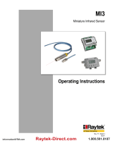
2.5 Physical user interface
1 Display °C or °F as well as active limit switches
2 LED display
3 Parallax free thru-lens view finder
4 Setting keys (operate with Tip of ball-point pen)
5 Parameter indicator
6 Main connection cable and
additional cable for limit contacts
7 Laser warning label (only instruments with
laser targeting light)
8 Fixed or focusable optics
9 Label with optics information
10 Mounting holes
11 Cap for scanner adjustments
(only types IS 12-S or IGA 12-S)
12 Type label (bottom side of the instrument)
2.6 Accessories (Option)
Numerous accessories guarantee easy installation of the pyrometers. The following overview
shows a selection of suitable accessories. You can find the entire accessory list with all reference
numbers in Section 10.2 Reference numbers accessories).
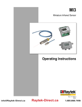
2.6.1 Mounting
For mounting and aligning the pyrometer to the
measured object, a mounting angle or ball and
socket mountings are available. The ball and socket
mounting is an easy way to align the pyrometer or
water cooling jacket (ball and socket mounting steel)
to the measured object. The quick-clamping-screws
of the ball and socket mounting enable easy and fast
adjustment of the pyrometer in all directions.
Ball and socket
mounting
Ball and socket
mounting, steel
Mounting
angle
1
2
3
4
6
10
11
8
7
5
12
9

IS 12 / IGA 12 Manual Introduction • 13
2.6.2 Cooling
The pyrometer can be used in ambient temperatures
outside of the specifications if preventive
maintenance is taken.
The cooling plate is used to protect the pyrometer
from heat coming from the front. The completely
covered water cooling jacket made from stainless
steel protects the pyrometer if exposed to a hot
environment. It is designed for ambient
temperatures up to 180 °C.
Water cooling jacket
Cooling plate
2.6.3 Miscellaneous
The air purge protects the lens from dust and
moisture contamination. Using dry and oil-free
pressurized air, it generates an air stream shaped like
a cone.
The rotary mirror attachment ROT 10 can only be
used in combination with pyrometers with fixed
optics. A rotating mirror system moves the measuring
beam in a line over the measuring object with a
scanning angle up to 73°.
Air purge
Rotary mirror attachment ROT 10
2.6.4 Displays
In addition to the built-in temperature indicator of
the pyrometer, LumaSense offers several digital
displays which can also be used for remote
parametrizing of the pyrometer.
Digital display DA 6000
LED large display
Note: In instances where s
trong incidence of daylight or lamp light into the view finder
can affect the measurement, the ocular has to be covered.


IS 12 / IGA 12 Manual Controls and Installation • 15
3 Controls and Installation
3.1 Electrical Installation
The pyrometers are powered by a voltage of either 24 V DC (15 to 40 V DC) or 24 V AC
(12 to 30 V AC), 48 to 62 Hz. Once connected to power, the instrument operations immediately
and needs no warm-up time. To switch off the instrument, unplug the connector.
To meet the electromagnetic requirements, a shielded connecting cable must be used. The
shield of the connecting cable has to be connected only on the pyrometer side to avoid ground
loops.
LumaSense offers connecting cables, but they are not part of
standard scope of delivery. The main connecting cable has wires
for power supply, interface, analog output, external laser switch
and external clear of maximum value storage via contact (see
Chapter 10, Reference numbers) and 12 pin angle connector.
The cable includes a short RS232 adapter cable with a 9 pin
SUB-D connector for direct PC communication. This adapter is
not used in combination with RS485 interface.
For use of the limit contacts, the separate additional cable has
to be used.
connector connector
for main for additional cable
connection cable for limit switches
3.1.1 Pin assignment for the connector on the back of the pyrometer
For the main connection cable
Pin Color Indication
K
A
B
C
D
J
G
F
E
H
M
L
Pin assignment
of left connector
(side of
male inserts)
K
white
+ 24 V power supply (or 24 V AC) (12 ... 30 V)
A
brown
0 V power supply
L
green
+ I
outp.
analog output
B yellow
– Ioutp. analog output
H
gray
External switch for targeting light (bridge to K)
J pink External clearing of maximum value storage (bridge to
K) *
)
or output for switch contact (see Section 5.13)
G
red
DGND (Ground for interface)
F
black
RxD (RS232) or B1 (RS485)
C violet TxD (RS232) or A1 (RS485)
D
gray/pink
B2 (RS485) (bridge to F)
E
red/blue
A2 (RS485) (bridge to C)
M orange
Screen only for cable extension
don’t connect at the switchboard
*) For setting of clear time to "extern" (see 5.3, clear time for maximum value storage).
For additional limit contacts cable
The instrument is equipped with two independent relay limit switches. These are two separate
switch-over relay contacts, changing its state if the adjusted temperatures are exceeded.

IS 12 / IGA 12 Manual Controls and Installation • 16
Pin
Color
Indication
6
8
4
5
3
1
2
7
Pin assignment
of right connector
(side of male inserts)
7
pink
Limit contact S1
(drawing shows status without
power or with exceeded limits)
5
white
1
yellow
3
grey
Limit contact S2
(drawing shows status without
power or with exceeded limits)
6
green
4
brown
2
blue
8
red
The drawing of the limit contacts indicates their switch status without power. The limit contacts
switch after supplying the pyrometer with power. If the temperature exceeds the adjusted limit
value, the corresponding limit contact switches back in the first position and is indicated by the
corresponding LED on the pyrometer (see 4.2 under Limit contacts).
Any temperature value within the range of the pyrometer is adjustable. You can set the limits
directly on the pyrometer (see 5.6 SETP (limit contacts)) or via InfraWin software. The switch
time of the relay contacts is 2 ms plus the response time of the pyrometer.
To avoid oscillating of the switch in the switch point, the contacts switch with a hysteresis (works
setting ±2 °C, adjustable between ±2 and ±20 °C). If required, the hysteresis can be set via the
InfraWin software. Setting hysteresis directly on the instrument is not possible.
3.1.2 Connecting the pyrometer to a PC
The pyrometers are equipped with a serial interface RS232 or RS485 (switchable at the
pyrometer). Only one pyrometer can be connected on the standard PC RS232 interface. Only
short distances can be transmitted with RS232 and electromagnetic interferences can affect the
transmission.
The pyrometer is equipped with an RS485 serial interface. With the RS485, long transmission
distances can be realized and the transmission is, to a large extent, free of problems. The RS485
also allows several pyrometers to be connected in a bus system.
If an RS485 connection is not available at the PC, it can be accomplished using an RS485 or RS232
to USB connector. When using a RS485 to USB adapter, make sure that the adapter is fast
enough to receive the pyrometer’s answer to an instruction of the master. Most of the
commonly used adapters are too slow for fast measuring equipment, so it is recommended to
use the USB-RS485 adapter cable, part number 3 826 750.
With a slow RS485 connection it is also possible to set a wait time at the pyrometer which delay
the response of a command to the pyrometer (see 5.12 Wait time tw).
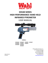
Connecting to RS232 interface
The transmission rate (in baud) of the serial
interface is dependent on the length of the
cable. Values between 2400 and 115200 Bd
may be set.
The baud rate has to be reduced by 50%
when the transmission distance is doubled
(see also 5.10 kBaud (baud rate)).
Typical cable length for RS232 at 19200 Bd is
7 m.
K
A
B
C
D
J
G
F
E
H
M
L
1
2
3
4
5
6
7
8
9
DGND (red)
RxD (black)
TxD (violet)
Pyrometer’s side
(soldering side)
cable
PC’s side
(soldering side)

IS 12 / IGA 12 Manual Controls and Installation • 17
Connecting to RS485 interface
Half-duplex mode:
A1 and A2 as well as B1 and B2 are
bridged in the 12-pin round
connector of the connecting cable,
to prevent reflections due to long
stubs. It also safeguards against the
interruption of the RS485 Bus
system should a connecting plug be
pulled out. The master labels mark
the connections on the RS485
converter. The transmission rate of
the serial interface in Baud (Bd) is
dependent on the length of the
cable. Values between 2400 and
115 kBd may be set.
The baud rate is reduced by 50%
when the transmission distance is doubled (see 5.10 kBaud (baud rate)). Typical cable length
for 19200 Bd is 2 km.
3.1.3 Connection of additional analyzing devices
Additional analyzing instruments (such as LED digital display instruments) only need to be
connected to a power supply and the analog outputs from the pyrometer. Another Instrument,
such as a controller or printer, can be connected to the display in series as shown below (total
load of resistance max. 500 Ohm).
yellow
LED digital display
Controller
Power supply
green
brown
white
230 V ~
24 V DC
°C
Writer
3.2 Sighting
For exact aiming to the object, the pyrometers are equipped with a thru-lens view finder and
optionally with an additional laser targeting light.
3.2.1 Thru-lens view finder
In the optimized thru-lens view finder, a circle marks the exact
position and size of the measuring spot. Pyrometers with
temperature ranges exceeding 1500 °C are equipped with an
adjustable eye protection filter. Turning the ocular changes the
filter from bright to dark.
Terminator 120 Ohm
A
B
S
K
A
B
C
D
J
G
F
E
H
M
L
K
A
B
C
D
J
G
F
E
H
M
L
K
A
B
C
D
J
G
F
E
H
M
L
DGND
B1
A2
B2
A1
DGND
B1
A2
B2
A1
DGND
A2
B2
A1
B1
Master
Pyrometer 32
e.g. address 31
Pyrometer 2
e.g. address 01
Pyrometer 1
e.g. address 00

IS 12 / IGA 12 Manual Controls and Installation • 18
3.2.2 Laser targeting light
In addition to the thru-lens view finder, the instruments can be equipped with a laser targeting
light. The laser point marks the center of the spot, not the exact size. The laser targeting light
can be used without affecting the measurement.
3.3 Optics
The pyrometers are equipped ex works with a fixed or a focusable optics. The smallest spot size
for the fixed optics is shown for the specified measuring distance. With the focusable optics,
the smallest possible spot size can always be adjusted for each distance within the optics limits.
The selection of a suitable fixed or focusable optics depends on different factors:
• Very short measuring distances up to 250 mm to achieve extremely small spot sizes are
only available as fixed optics.
• The rotary mirror attachment ROT 10 can only be used in combination with fixed optics.
• The three focusable optics allow the exact adjustment of any required measuring
distance from 277 mm.
• Focusable optics offer high flexibility to adapt the instrument to applications with
different measuring distances.
3.3.1 Fixed optics
IS 12; IS 12-S:
MB 14
MB 16; 18; 20L
MB 25; 35L
IGA 12; IGA 12-S:
MB 10
MB 13; 14L
MB 18
MB 23
Optics
Measuring
distance
a [mm]
Spot size M90 [mm]
1
a = 80 mm
0.9 mm
0.7 mm
0.3 mm
0.1 mm
2
a = 160 mm
0.7 mm
0.6 mm
0.4 mm
0.2 mm
3
a = 250 mm
1 mm
0.8 mm
0.5 mm
0.3 mm
4
a = 660 mm
2.3 mm
2 mm
1.2 mm
0.7 mm
5
a = 1300 mm
5.5 mm
3.8 mm
2.8 mm
1.4 mm
6
a = 5600 mm
19 mm
15 mm
12 mm
6.4 mm
Aperture D [mm] *
19 mm
13.5 mm
10 mm
7 mm
*) The aperture is the effective lens diameter.
Measuring distance
The spot sizes, mentioned in the table above, will be only achieved at the measuring distances
of the corresponding optics. Decreasing or increasing the measuring distance enlarges the spot
size. Make sure that the measuring object is at least as big as the spot size. A tape measure can
be used to determine the distance between object and pyrometer. The measuring distance is
always measured from the front of the lens.
• Instruments equipped with thru-lens view finder: The measuring object will be
shown in the view finder of the pyrometer as a sharp image only in the measuring
distance of the corresponding optics (e.g. optics 1 at 80 mm). The circle in the view
finder marks the position of the spot.
• Instruments equipped with thru-lens view finder and laser targeting light: The
laser shows its smallest spot in the measuring distance of the corresponding optics
(e.g. optics 1 at 80 mm) and it marks the center of the spot, not its size.

IS 12 / IGA 12 Manual Controls and Installation • 19
Warning: To reduce the risk of injury to the eyes, do not look
directly into the targeting laser and do not point the targeting laser
into anyone's eyes. The instrument is equipped with a class II laser
that emits radiation.
Note: The pyrometer can measure objects at any distance but the object has to be
bigger than or at least as big as the spot size of the pyrometer in the measuring
distance.
Calculating the spot sizes on different measuring distances:
Spot sizes for other measuring distances can
be calculated with the following equations
or with the IR calculator of the InfraWin
software.
Table values: a1 = measuring distance
M1 = spot size
D = aperture
3.3.2 Focusable optics
Focusable optics IS 12
Measuring
distance
a [mm]
Spot size M90 [mm]
Objective
length
S [mm]
MB 14
MB 16
MB 18; 20L
MB 25; 35L
Optics
1
a = 277 mm
0.9
0.6
0.6
0.4
30
a = 400 mm
1
0.8
0.8
0.5
9.5
a = 533 mm
1.4
1.1
1.1
0.7
0
Optics
2
a = 388 mm
1
0.8
0.8
0.45
30
a = 700 mm
1.8
1.5
1.5
0.8
8.6
a = 1170 mm
3
2.4
2.4
1.4
0
Optics
3
a = 550 mm
1.5
1
1
0.6
30
a = 3000 mm
9
6
6
3.3
3.3
a = 9500 mm
25
19
19
10.6
0
Aperture D [mm]*
13.5 to 17
13.5 to 17
10 to 13
5 to 7

IS 12 / IGA 12 Manual Controls and Installation • 20
Focusable optics IGA 12
Measuring
distance
a [mm]
Spot size M90 [mm]
Objective
length
S [mm]
MB 10
MB 13; 14L
MB 18
MB 23
Optics
1
a = 280 mm
1.3
0.9
0.5
0.4
30
a = 400 mm
17
1.1
0.7
0.5
9
a = 520 mm
2
1.2
0.8
0.7
0
Optics
2
a = 390 mm
1.4
1
0.6
0.45
30
a = 700 mm
2.6
1.5
1
0.8
7.9
a = 1090 mm
4.1
2.4
1.6
1.3
0
Optics
3
a = 550 mm
2
1.2
0.8
0.6
30
a = 3000 mm
10.7
5.9
4.3
3.8
2.2
a = 5600 mm
20
11
8
7
0
Aperture D [mm] *)
13.5 to 17
13.5 to 17
13.5 to 17
10 to 13
*) The aperture is the effective lens diameter. It is depending on the objective length. The biggest
aperture value belongs to the fully extended objective (S = 30), the smallest aperture value for
objective length S = 0. Intermediate values have to be interpolated.
Adjusting the required measuring distance
The required measuring distance must be adjusted to achieve the spot size mentioned in the
tables above. This can be done between the smallest and the biggest limit value.
Note: The measuring object has to be bigger than or at least as big as the spot size
of the pyrometer.
To release the optics, turn it counterclockwise. Then it
can be pushed or pulled to find the correct measuring
distance. To fix the optics, turn the optics clockwise.
Adjusting the measuring distance with help of
the table:
The table mentions the minimum and maximum
measuring distance for each of the three focusable
optics. This corresponds to the longest or the shortest
objective length. As an example, a further value
between max. and min. is shown. The objective length
“S” can be measured with a caliper.
release
fix
push / pull
Page is loading ...
Page is loading ...
Page is loading ...
Page is loading ...
Page is loading ...
Page is loading ...
Page is loading ...
Page is loading ...
Page is loading ...
Page is loading ...
Page is loading ...
Page is loading ...
Page is loading ...
Page is loading ...
Page is loading ...
Page is loading ...
Page is loading ...
Page is loading ...
Page is loading ...
Page is loading ...
Page is loading ...
Page is loading ...
/