Quick Start Guide
-FR24R
Further information on the device is available at www.lightware.com.
The User’s Manual is also available via the QR code below:
Contact Us
+36 1 255 3800
+36 1 255 3810
Lightware Visual Engineering PLC.
Budapest, Hungary
Doc. ver.: 1.1
19210020
Important Safety Instructions
Please read the supplied safety instruction
document before using the product and
keep it available for future reference.
¢
CAUTION - The use of controls
or adjustments or any performance
of procedures other than those specied herein may result in hazardous radiation
exposure.
Introduction
Thank you for choosing Lightware. MX2M-FR24R is a member of the Lightware MX2
modular matrix switcher series, supporting uncompromised 4K UHD resolution at 60Hz with
4:4:4 sampling pattern and with downconversion capabilities to 4:2:2, supporting HDCP 1.x
and 2.3, 3D, Dolby TrueHD and DTS-HD Master Audio. The non-blocking matrix architecture
distributes and switches 24 video signals to 24 outputs, distributed along six 4-port boards
respectively per direction.
Besides the six 4-port input and six 4-port output video boards, there are four low speed
installable slots for Dante audio.
Control for connected extenders is served by Ethernet layer. The Ethernet layer can also be
used for IP extension, as well as for command injection for IR and serial control by third party
devices.
For operation safety power redundancy is available, and PSU drawers are eld-exchangeable
for ease of maintenance.
Box Contents
Matrix switcher frame
with rack mounting ears
IEC power cable (2x) UTP patch cable (3 m)
Handle pair with 4 pcs M5
at head screws
Safety & Warranty Info,
Quick Start Guide
Safety and
Warranty
Info
Quick
Start
Guide
9 q84
321 7 w65
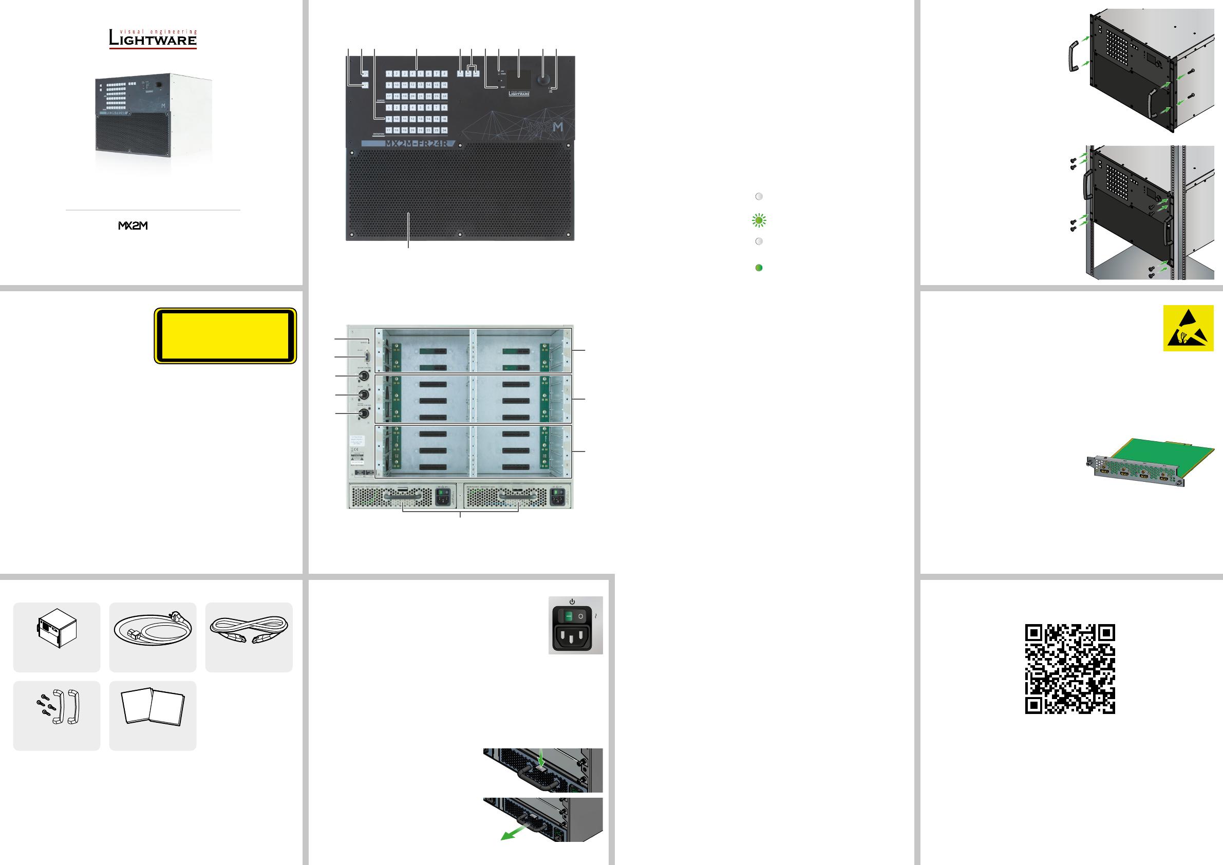
Front View
Rear View
1
Output lock Locks and protects one or more outputs.
2
Control lock Disables or enables front panel button operations. Red light
means the switching and function buttons are disabled.
3
Destinations Buttons to select an output or to see the state of an output.
4
Sources Buttons to select an input, to select a preset number or to view
the state of the selected input port.
5
Take / Auto Switching between Take and Autotake working modes; keep
the button pressed for 3 seconds to toggle the modes.
6
Preset buttons Performing preset operations (Load and Save).
7
Reset button Reboots the matrix; the same as switching it off and on again.
8
Status LEDs The status LEDs give immediate feedback about the matrix.
LIVE off The device is powered off.
blinking
(green)
The unit is on and operates
properly.
POWER off The unit is powered off or it
has internal voltage problem.
on (green) The device is powered on.
9
LCD screen LCD screen showing the most important settings and
parameters in the front panel menu.
q
Jog dial control
knob
Easy setting and menu navigation by the jog dial control.
w
USB control USB connection for Lightware Device Controller (LDC)
software.
e
Ventilation grille
and dustlter
To ensure the correct ventilation and avoid overheating provide
enough free space around the ventilation holes.
r
Auxiliary board
slots
Board slots for the auxiliary (AUX) I/O boards. These slots
support low-speed boards only.
t
Input board
slots
Board slots for the AV input boards. These slots support high-
speed input boards and low-speed boards either.
y
Output board
slots
Board slots for the AV output boards. These slots support high-
speed output boards and low-speed boards either.
Mounting Options
Fixing the Handles
Two handles can be mounted on the rack
ears of the matrix switcher. Fasten the 2x
2 pcs M5 at head xing screws to x the
handles to the rack ears.
Mounting as a Standard Rack
Installation
Two rack ears are supplied with the product,
which are xed on left and right side with 2x
4 pcs xing screws as shown in the picture.
The default position allows mounting the
device as a standard rack unit installation.
¢
Always use all the eight screws
for xing the device ears to the rack
rail. Choose properly sized screws for
mounting. Keep minimum two threads
left after the nut screw.
The screws for the rack cabinet are not
supplied to the device.
The matrix is rack-size width and 8U
high.
u
Power supply
units
Hot swap slots for power supply units. The matrix has
redundant PSUs which can be switched on and off without
interrupting the video transmission. Using one or both of the
PSUs at the same time is also possible.
The double PSU allows to connect them for two different AC
power lines to ensure the continuous power for the matrix.
i
Uplink /
Secure control
connector
Neutrik etherCON Ethernet connectors with 1 Gbps Ethernet
connections for user Ethernet access or control the matrix
switcher.
o
Uplink
connector
Neutrik etherCON Ethernet connectors with 1 Gbps Ethernet
connections for user Ethernet access.
p
Secure control
connector
Neutrik etherCON Ethernet connector with 1 Gbps Ethernet
connection to control the device and rmware upgrade
purpose.
a
RS-232
connector
9-pole D-SUB connector for serial communication to control
the device.
s
Service button Hidden button for special operations.
Powering On
Connect the power cords to the AC input of the power supply units and
turn it on by the power switch. During the initial self-test and loading of
the latest settings, The matrix is about to start text appears on the LCD
screen and the router reloads its last conguration.
Redundant, Hot-Swappable Power Supplies
The matrix has redundant PSUs which can be switched on and off without interrupting
the video transmission. Using one or both of the PSUs at the same time is also possible.
The double PSU allows to connect them for two different AC power lines to ensure the
continuous power for the matrix. The PSU units are hot-swappable.
Removing of the PSU Units
CLASS 1 LASER PRODUCT
CAUTION - CLASS 3R INVISIBLE LASER
RADIATION WHEN OPEN. AVOID DIRECT
EYE EXPOSURE.
Board Replacement
¢
Please pay attention to the protection against electrostatic
discharge when touching a board. Do not touch the electrical
components on the board as the electrostatic discharge may damage
them.
¢
Please check the orientation of the slots. The AUX, IB and OB cards are assigned
to dedicated board slots in the matrix. See the layout of the input/output board slots on
the other side of this document.
The MX2M series I/O boards are hot-swappable devices. The matrix switcher is not
required powering off before the board replacement procedure.
The steps of replacing an auxiliary, input or output board is the following:
1. Disconnect all the cables from the rear side
of the affected board.
2. Loose the xing screws on the rear side of
the board.
3. Pull out the board and put it in an ESD-safe bag.
4. Place the new board into the desired empty
slot. Be careful when you insert the board into the socket connector.
5. Tighten the screws to x the board to the frame.
6. Connect the necessary cables to the boards and switch on the matrix.
7. Wait until the booting procedure of the board is completed.
8. Connect to the matrix switcher using Lightware Device Controller (LDC) to set the
necessary port parameters.
100-240 V AC
ON OFF
1. Turn off the PSU using the power switch and disconnect the power cord.
2. Push down the xing plate on the PSU.
3. Pull out the PSU using the handle.


