RS-232
LOCAL CONTROL
RoHS
Made in EU, HU
OUTPUTS
INPUTS
1 2 3 4 5 6 7 8 9 10 11 12 13 14 15 16
+3.3V +5V RS-232
LAN
100-240V 2.1-0.9A 50-60Hz
FUSE: F 3.15A 250V
1 2 3 4 5 6 7 8 9 10 11 12 13 14 15 16
CPU LIVE
RESET
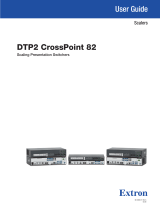
20m DVI cable
PC or Mac
DVI-HDCP-
TPS-RX97
DVI-HDCP-
TPS-RX97
DVI-HDCP-
TPS-TX97
DVI-OPT-
TX220-Pro
DVI-OPT-
RX220-Pro
DVI-HDCP-TPS-TX97
PC or Mac
MX16x16DVI-Plus
PC or Mac Projector Projector
Projector
Single fiber multimode
optical cable up to 2500m
DVI
monitor
DVI monitor
20m DVI cable DVI cable
DVI cable
DVI cable
DVI
cable
DVI
cable
DVI
cable
TPS
(up to 170m)
TPS
(up to 170m)
DVI
cable
DVI
cable
DVI
cable
DVI
cable
DVI-HDCP-TPS-TX97
Sn :
Made in EU, Hungary
RoHS
Ethernet 10/100
Bidirectional IR
Bidirectional RS-232
TPS Long Distance Transmitter
HDMI, 3D, 4K supported
For best performance use CAT6 or CAT7 SFTP cable
Check compatibility before connecting devices.
When remote power is enabled, 12V present on TPS connector.
PIN: 2mm
12V 1A DC
TPS OUT (PoE)
DVI-HDCP-TPS-RX97
Sn :
Made in EU, Hungary
RoHS
Ethernet 10/100
Bidirectional IR
Bidirectional RS-232
TPS Long Distance Transmitter
HDMI, 3D, 4K supported
For best performance use CAT6 or CAT7 SFTP cable
Check compatibility before connecting devices.
When remote power is enabled, 12V present on TPS connector.
PIN: 2mm
12V 1A DC
TPS OUT (PoE)
CONTROL
LOCK
Remote Operation
The matrix can be controlled through various interfaces remotely. The feature allows using
functions which are not accessible via the front panel. Also, this helps system integrators and
operators to control multiple devices in a complicated system through a single user interface.
Control Interfaces
The user can connect to the matrix through Ethernet (TCP/IP), or Serial port (RS-232). After
establishing the connection, generally, there is no difference between the connection types.
Ethernet port can be connected to a LAN hub, switch, or router with a UTP patch cable. If
connecting to a computer directly, a cross-link UTP cable has to be used!
Multiple Simultaneous Connections
Ethernet and Serial connections can be used at the same time. However, only one connection
is allowed for Lightware Device Controller (LDC) via the Ethernet port.
Control Protocols
The matrix can be controlled with multiple control protocols. Lightware routers have a special
protocol, but to inter-operate with third-party devices, a secondary protocol is also provided.
For detailed information about control protocol, please read the User’s manual of the device.
User interface Ethernet port RS-232 port
Lightware Device Controller
Built-in website
Third party control system
Web Control – Using the Built-in Website
The matrix switchers have a built-in web page, which can be accessed over TCP/IP protocol
and offers you full control over all settings even if you don’t have the opportunity to install new
programs. The router’s built-in website is compatible with most widely spread browsers and
requires no additional software components. To access the web page just run your preferred
web browser and type the IP address of the router as a URL. The computer and the router
have to be in the same subnet.
The only way to nd out the router’s IP address (if it is not known) is to search for devices
with the Lightware Device Controller software. If this is not possible for some reason, the IP
address can be reset to factory default (192.168.254.254) with the front panel buttons.
Only one opened web page is allowed simultaneously. Other TCP/IP connections are
prohibited while the web page is opened.
Establishing the Connection
If the computer has multiple Ethernet connections (e.g. Wi-Fi and LAN connections
are used simultaneously) you will have to know the IP address for the one that is used for
controlling the matrix.
1. Connect the matrix switcher and the computer via :
Ethernet by a LAN patch cable (to a Hub, Switch or Router), or
Directly by a LAN cross-link cable.
2. Change to the desired IP settings if it is needed.
3. Type the IP address to the address bar of the web browser. After a few seconds, the
Control menu appears. The current state of the crosspoint is displayed.
CONTROL LOCK
If the button illuminates in red the switching- and function buttons are disabled.
Press the Control lock button to toggle the state.
When the front panel buttons are locked, remote control (RS-232, Ethernet)
is still available.
LCD Menu Operation Modes
(Valid for the MX8x8DVI-HDCP-Pro, and MX8x8HDMI-Pro switchers.)
Normal Mode
Most settings can be done in this mode; this is the default mode after powering on.
EDID Mode
Use this mode to set up the emulated EDID on the inputs, learn EDID from the outputs or to
view the EDID memory. This mode is activated when the EDID button is illuminated. You can
enter or exit this mode by pressing the EDID button.
Signal Present Mode
This mode is for checking the presence of the display devices and incoming signals. It is
activated when the SIGNAL PRESENT button is illuminated. You can enter this mode or exit
by pressing the SIGNAL PRESENT button.
Network Settings - Resetting the IP Address with Front Panel Buttons
The factory default IP address or DHCP mode can be set by the front panel buttons quickly. To
reset the IP conguration perform the followings:
1. Switch the router to Take mode if used previously in Autotake mode by pressing Take
button for 3 seconds (light will go off).
2. Press and release Control Lock button (it lights in up red continuously).
3. Press and keep pressed the Output Lock button (the current protocol is indicated).
4. Press and release the
a. Load Preset button to set the factory default static IP settings:
IP address: 192.168.254.254
port number: 10001
subnet mask: 255.255.0.0
gateway: 0.0.0.0
b. Save Preset button to set DHCP enabled (dynamic IP address):
IP address: Acquired with DHCP
port number: unchanged
subnet mask: Get from DHCP server
gateway: Get from DHCP server
Setting a dynamic IP address by the front panel buttons is available only in case of the
following products: MX8x8HDMI-Pro, MX8x8DVI-HDCP-Pro, MX-...-Slim and MX-...-Plus
matrix switchers.
5. A light sequence will occur to conrm the command.(Take/Auto, Load Preset and Save
Preset buttons will light up one after the other).
6. Reinsert the LAN cable to the Ethernet port if it was unplugged.
7. Wait about 20 seconds before connecting the router via Ethernet.
The factory default IP port no. is 10001.
Typical Application - MX16x16DVI-Plus
Front Panel Controls in AUTOTAKE Mode
Autotake mode is useful when immediate actions must be taken or fast switching
is needed between sources on a particular destination. In this mode switching
occurs immediately upon pressing one of the input selector buttons.
Switching operations
1. First press and release the desired source button.
The pressed source button and all destination buttons
which are currently connected to the source light up.
SOURCES
DESTINATIONS
2. Press and release the desired destination buttons
which have to be (dis)connected to/from the selected
source. The preselected destination buttons will blink.
SOURCES
DESTINATIONS
3. Press and release the Take button. The selected input
is switched to the selected output(s).
Lock an output
1. Press and release the Output Lock button. It starts to
blink and all the buttons of any locked destinations light
up (view state).
TAKE
AUTO
TAKE
AUTO
Software Control – Using Lightware Device Controller (LDC)
The device can be controlled from a computer using the Lightware Device
Controller software. The application is available at www.lightware.com, install
it on a Windows PC or a macOS and connect to the device. The following
ways are available to connect to the device directly.
Local RS-232 Port
Connect a serial cable between the matrix and the computer and start the LDC. Press the
Query button of the connected COM port to list the device, select it then press Connect. The
factory default RS-232 port settings are the followings:
9600 Baud, 8 data bits, No parity, 1 stop bit.
LAN Port
Connect the supplied LAN cross-link cable between the matrix and the computer for direct
connection or connect to an Ethernet by a patch cable. The default parameters are listed
under Network settings section.
Powering On
Connect the power cord to the device’s IEC C14 standard power input connector. The router
is immediately powered on when the power cord is connected to the AC source (on Slim
matrix switchers the power switch has to be in position ‘ON’). If the self-test is nished the last
conguration is reloaded and the appliance is ready to use.
After switching ON, the router reloads the latest settings which had been used before it
was turned off. The router has an internal emergency memory that stores all current settings
and tie congurations. This memory is independent from presets and invisible for the user.
This built-in feature helps the system to be ready immediately in the case of a power failure or
accidental power down.