Page is loading ...

ELR-63
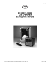
MECHANICAL INSTALLATION
TERMINAL CONNECTION
Page - 1
Earth Leakage Relay
FEATURE
TECNICAL SPECIFICATION
Earth Leakage Current Monitoring In 1Ø - 2W, 3Ø-3W
And 3Ø-4W
System
Test Mode Available.
Auto/Manual Triping Reset Facility.
LED Indiction (25%,50%,75%)
Test/Trip Reset Via Front Key / Remote
ENVIRONMENT CONDITION :
Operating Temp. 0 - 55°C
Relative Humidity 95% RH
Input Current
Display Currant Range
Resolution
0.00 To 3.00 mA AC From CBCT
0.03 To 3.00 Amp
INPUT SPECIFICATION :
If Current in mA = 1 mA
If Current in Amp = 0.01A
Display
Keys
3 Digit, 7 Seg., 0.36”, Red.
SET, INC, DEC.
Relay
Relay Type
Rating
1 Nos.
NO - C
5A,230V AC Resistive Load
AUXILIARY SUPPLY :
Supply Voltage 100 To 250 V AC
Power Consumption
(VA Rating) 3VA @ 230 VAC MAX
DISPLAY & KEYS :
OUTPUT SPECIFICATION :
FRONT VIEW
SIDE VIEW
BACK VIEW
76 mm
76 mm
76 mm
84 mm
27.5 mm 27.5 mm
S1 S2
CBCT
L1
L2
L3
N
TO
LOAD
Range:
30mA To 3Amp
AC
Made in India
www.multispanindia.com
LN
100-250V AC,
50/60Hz
!
LNS1
NO C
S2
25% 50%
AELR 63
RST/TST
RST/TST
SET
75% R

Page -1
WARNING GUIDELINES
KEY OPERATION
SAFETY PRECAUTION
!
Read complete instructions prior to installation
and operation of the unit.
WARNING : Risk of electric shock.
All safety related codifications, symbols and instructions that
appear in this operating manual or on the equipment must be
strictly followed to ensure the safety of the operating personnel
as well as the instrument.
If all the equipment is not handled in a manner specified by
the manufacturer, it might impair the protection provided by the
equipment.
MAINTENANCE
1. The equipment should be cleaned regularly to avoid blockage
of ventilating parts.
2. Clean the equipment with a clean soft cloth. Do not use
isopropyl alcohol or any other cleaning agent.
3. Fusible resistor must not be replaced by operator.
WARNING : Risk of electric shock.
1. To prevent the risk of electric shock, power supply to the
equipment must be kept OFF while doing the wiring
arrangement. Do not touch the terminals while power is
being supplied.
2. To reduce electro magnetic interference, use wire with
adequate rating and twists of the same of equal size shall
be made with shortest connection.
3. Cable used for connection to power source, must have a
cross section of 1mm or greater. These wires should have
insulations capacity made of at least 1.5kV.
4. When extending the thermocouple lead wires, always use
thermocouple compensation wires for wiring for the RTD
type, use a wiring material with a small lead resistance
(5 max per line) and no resistance differentials among
three wires should be present.
5. A better anti-noise effect can be expected by using
standard power supply cable for the instrument.
Ω
INSTALLATION GUIDELINES
1. Do not allow pieces of metal, wire clippings, or fine metallic
fillings from installation to enter the product or else it may
lead to a safety hazard that may in turn endanger life or
cause electrical shock to the operator.
2. Circuit breaker or mains switch must be installed between
power source and supply terminal to facilitate power ‘ON’
or ‘OFF’ function. However this mains switch or circuit
breaker must be installed at convenient place normally
accessible to the operator.
3. Use and store the instrument within the specified ambient
temperature and humidity ranges as mentioned in this
manual.
OPERATION MODE
For 2 sec
For 5 sec
PARAMETER SETTING MODE
For 3 sec
FUNCTION KEY PRESS
To Enter in Parameter Setting
To Enter in Test Mode
To Reset the Relay Contact
Manually After Tripping
To Increment Parameter Value
To Decrement Parameter Value
To Save & Exit From Parameter
Setting Mode
1) To install the instrument on a DIN rail, raise the clamp at the
back of the instrument and place it on the rail. Now release
the clamp, so the instrument fits on the DIN rail.
2) Ensure proper fitting of the instrument by pulling it outwards.
3) To remove the instrument raise the clamp to release it from
the DIN rail.
4) The equipment in its installed state must not come in
close proximity to any heating source, caustic vapors, oil
steam, or other unwanted process byproducts.
5) Do not connect anything to unused terminals.
MECHANICAL INSTALLATION

LED STATUS INDICATION
25% 50% 75% R
1
5
23
4
A
1) 25% LED
20% < Leakage
Current< 25% LED Blinking
Leakage Current ≥ 25%
LED Continuously ON
Leakage Current≤ 20%
LED OFF
2) 50% LED
45% < Leakage
Current< 50% LED Blinking
Leakage Current ≥ 50%
LED Continuously ON
Leakage Current≤ 45%
LED OFF
3) 75% LED
70% < Leakage
Current< 75% LED Blinking
Leakage Current ≥ 75%
LED Continuously ON
Leakage Current≤ 70%
LED OFF
999 mA 1.00 A Reading
Control Output Indication (ON/OFF)
4) Relay LED
→
5) AMP LED
9 9 9 1 0 0
A
mA
A
mA
Leakage Current > 999 mA
Then Amp LED Will ON
3 0
/
/
Delay time
Trip Setting
Hysteresis
Healthy condition relay
mode
ON/OFF
Reset Mode
Auto /Manual
30mA to 3Amp
Set leakage current
0.00 to 9.99 sec
75% or 100% of set point
0.00 to 2.99 Amp
Enter password “123”
Password
To be continued
mA (Actual Value of Earth
Leakage Current)
p a s
1 2 3
s e t
3 0 0
D L y
0 0 0
t r p
1 0 0
r L y
O F F O N
O D
a U t a N
H Y S
1 0 0
Press key
Press key
Press key
Press key
Press key
Press key
Press key
Press key
Press key
Press key
Press key
Press key
Press key
Press key
Press key
PARAMETER SETTING

To Enter In Test Mode
NO C
→
Short RST/TST
pin for 5 second
OR Press Key for 5 sec
- Display Shows
T S T Relay on
R
- To exit from test mode, short RST/TST Pin for 1 second
OR Press key for 1 sec.
Earth Leakage Current
Tripping Setting
Set Point
Time
TRIP
RLY-ON
Delay
Time
Delay
Time
Healthy Condition relay mode = ON
RLY-ON
RLY-OFF
HYST
2.00
1.99
Time
RLY-ON
Earth Leakage Current
Tripping Setting
Set Point
To Reset the Relay Contact after tripping two modes are
given.
NOTE: When Leakage Current < Setpoint
1) Auto Reset
Healthy Condition relay mode = ON
Trip Set Point = 2.00 Amp
Hysteresis = 0.1 Amp
NO C
→
Short RST/TST
pin for 2 second
OR Press Key for 2 Second
2) Manual Reset
Amp
Password enable/ disable
P A S
/
Enable /
Disable
E N B D I S
Press key for 3 sec to
save parameter & exit.
Press key
Specifications are subject to change, since development is a continuous process,
So for more updated operating information and Support,
Please contact our Helpline: 9978991474/76/82 or
Email at Ver:191201[email protected]
Page -2
TEST MODE
TRIP FUNCTION
RESET FUNCTION
/