Page is loading ...

Crestron Isys
TPS-2000L
5 Inch Lectern/Wall Mounted Touchpanel
Operations Guide

This document was prepared and written by the Technical Documentation department at:
Crestron Electronics, Inc.
15 Volvo Drive
Rockleigh, NJ 07647
1-888-CRESTRON
All brand names, product names and trademarks are the property of their respective owners.
©2003 Crestron Electronics, Inc.

Crestron Isys
TPS-2000L 5 Inch Lectern/Wall Mount Touchpanel
Contents
5 Inch Lectern/Wall Mount Touchpanel: TPS-2000L 1
Introduction ...............................................................................................................................1
Features and Functions................................................................................................ 1
Specifications ..............................................................................................................2
Physical Description....................................................................................................4
Industry Compliance ................................................................................................... 5
Setup .......................................................................................................................................... 6
Network Wiring........................................................................................................... 6
Identity Code ............................................................................................................... 7
Configuring the Touchpanel........................................................................................7
Hardware Hookup .....................................................................................................12
Mounting Options......................................................................................................13
Touchpanel Mounting ............................................................................................... 14
Touchpanel Removal.................................................................................................15
Recommended Cleaning............................................................................................16
Programming Software............................................................................................................16
Programming with the Crestron AppBuilder............................................................. 17
Programming with SIMPL Windows ........................................................................ 17
Programming with Crestron VisionTools
Pro-e ...................................................... 21
“Quick” Pushbuttons .................................................................................................26
Reserved Join Numbers.............................................................................................26
MultiByte International Characters ...........................................................................29
Uploading and Upgrading........................................................................................................ 29
Communication Settings ...........................................................................................30
Uploading a SIMPL Windows Program.................................................................... 32
Uploading a VT Pro-e Project ................................................................................... 33
Firmware Upgrade..................................................................................................... 35
Problem Solving ......................................................................................................................37
Troubleshooting......................................................................................................... 37
Further Inquiries ........................................................................................................38
Future Updates ..........................................................................................................38
Software License Agreement...................................................................................................39
Return and Warranty Policies .................................................................................................. 41
Merchandise Returns / Repair Service ...................................................................... 41
CRESTRON Limited Warranty.................................................................................41
Operations Guide – DOC. 5972A Contents • i


Crestron Isys
TPS-2000L 5 Inch Lectern/Wall Mount Touchpanel
5 Inch Lectern/Wall Mount
Touchpanel: TPS-2000L
5 Inch Lectern/Wall Mount
Touchpanel: TPS-2000L
Introduction Introduction
Features and Functions
The TPS-2000L, compact video touchpanel, is a 5-inch (12.7-cm) active matrix color
display panel with 320 x 234 resolution and 16-bit non-palette graphics. The purpose
of this unit is to provide a single, compact touchpanel that ends the age of walls
cluttered with switches, control panels, thermostats, etc. These wall-mounted panels
can be fully customized for any control environment – graphic icons and 10
programmable “quick” pushbuttons let users easily select and control any function.
The table after this paragraph provides a functional summary of the TPS-2000L.
TPS-2000L Functional Summary
• 5" (12.7 cm) active color matrix display
• 320 x 234 screen resolution
• 16 Bit non-palette graphics
• 2 Mb of Flash & 8 Mb of DRAM memory
• Built-in time-based correction for stable video & graphics
• Balanced/unbalanced composite video input; supports NTSC/PAL
formats
• Full screen video capability
• Up to 4,000 digital and analog signals; up to 999 serial signals
• Built-in microphone & two speakers (half duplex intercom capable)
• that can be programmed for quick access to regularly
used functions*
that can be programmed for quick access to regularly
used functions*
• Stores WAV sound files
• Automatic light sensor
• Capable of inverting image
Ten pushbuttons s
* Custom engraved keys can be ordered separately by using the Crestron Engraver Software. Version
2.0.0.9 or later is available from the Downloads | Software Updates section of the Crestron website
(www.crestron.com
).
The touchpanel is capable of replacing large, complicated panels with a series of
simpler screens; each can monitor and control a specific function. The panel features
balanced and unbalanced composite video input supporting both NTSC/PAL
Operations Guide – DOC. 5972A 5 Inch Lectern/Wall Mount Touchpanel: TPS-2000L • 1

5 Inch Lectern/Wall Mount Touchpanel Crestron Isys
TPS-2000L
formats. The unit has a single video input and can display multiple windows when
using a third party display splitter. A light sensor brightens or dims automatically
with changing room light conditions for easy viewing. The result is an outstanding
picture ideal for watching TV, previewing DVDs or checking security cameras. An
optional water-resistant cover provides protection around damp rooms such as the
pool or spa.
The exclusive “virtual pan and zoom” feature in these new Isys
panels is useful and
fun to use. Crestron implemented advanced digital video processor circuitry so that a
touch of the screen with a finger can allow panning across the video picture and
zooming in for the best view – even with standard security cameras.
The audio capabilities of these new Isys wall-mounted touchpanels allow for WAV
sound file storage and playback delivering instantaneous audio feedback, from sound
effects to the sound of one's own voice. A microphone, amplifier and speakers allow
talking with guests, as they are viewed on the security cameras, and adjustments for
volume, bass and treble provide for clear audio.
Specifications
The table below and on the next page provides a summary of specifications for the
TPS-2000L touchpanel.
Specifications for TPS-2000L Touchpanel
SPECIFICATION DETAILS
Power Requirements 13 Watts (0.54 Amp @ 24 VDC)
Default NET ID 03
Timeout
Adjustable from 0 to 120 minutes (Default = 10
min.)
Signal Join Maximums 4000 Digital and Analog, 999 Serial
Control System Update
Files
1,2,3
2-Series Control System Version C2-1008.CUZ or later
CEN/CN-TVAV Version 5.12.63V.UPZ or later
CNMSX-AV/PRO Version 5.12.63X.UPZ or later
CNRACKX/-DP Version 5.12.63W.UPZ or later
ST-CP Version 4.01.04S.UPZ or later
Acceptable File Extensions
4
SIMPL Windows
.smw
.spz
.bin
.csz
projectname.smw (source file)
projectname.spz (compiled file for 2-Series)
projectname.bin (compiled file for CNX generation)
projectname.csz
(compiled file for CNX generation with SIMPL+)
VT Pro-e
.vtp
.vtz
projectname.vtp (source file)
projectname.vtz (compiled file)
Firmware
.csf
TPS-2000.v.xxxxxx.csf (panel firmware)
(continued on next page)
2 • 5 Inch Lectern/Wall Mount Touchpanel: TPS-2000L Operations Guide – DOC. 5972A

Crestron Isys
TPS-2000L 5 Inch Lectern/Wall Mount Touchpanel
Specifications for the TPS-2000L Touchpanel (Continued)
SPECIFICATION DETAILS
Video
• Balanced (CAT5) video (via CNX-PVID or
CNX-RMCLV device) or unbalanced
composite video input through 8-position
mini connector (1 V
pp
).
• Built-in time base correction for stable video
and graphics
• Video can be displayed full screen or in a
window
• NTSC and PAL supported
• Adjustments for brightness, contrast, hue
and saturation available
Audio
• Balanced (2.0 V
RMS
) and unbalanced
(1.0 V
RMS
) line level microphone with AGC
output (3x sensitivity) via 8-position
mini connector.
• Balanced (4.0 V
RMS
) (via CNX-BIPAD or
CNX-RMCLV device) & unbalanced (2.0
V
RMS
) line level mono input through 8-
position mini connector.
• Speaker amplification: 2 Watts per channel
• WAV Audio Capacity > 3 minutes
5
Memory
2MB internal flash memory (1.5MB for user display
lists), 8MB of DRAM
Screen Dimensions
5"/12.7 cm diagonal
(2.9 in/7.5 cm High x 4.0 in/10.1 cm Wide)
Screen Viewing Angles
6
: Y Dir. (X=0
o
): +40
o
(from top), -65
o
(from bottom)
X Dir. (Y=0
o
): +65
o
(from right), -65
o
(from left)
Screen Resolution 320 x 234 pixels
Color 16 Bit non-palette graphics, 65,536 colors
Display Type Touch-sensitive active matrix color LCD
Enclosure
Plastic enclosure with injection-molded plastic
faceplate and keys in white.
CPU
63MIPs Coldfire processor running Isys generation
firmware
Cresnet Via 4-position mini-Cresnet connector
Operating Temperature
and Humidity
41º to 113º F (5º to 45º C),
10 to 90% Relative Humidity (non-condensing)
Dimensions and Weight
(with faceplate)
Height: 4.77 in (12.10cm)
Width: 6.73 in (17.10 cm)
Depth: 3.43 in (8.71 cm)
Weight: 1.41 lb (0.64 kg)
Programmable
Pushbuttons
10 with fixed join numbers. Join numbers are 1 to
5 (top to bottom) on the left side and 6 to 10 (top
to bottom) on the right side, regardless of screen
orientation. Custom engraved buttons can be
ordered separately from Crestron.
1. The latest versions can be obtained from the Downloads | Software Updates section of the Crestron
website (www.crestron.com)
. Refer to NOTE after last footnote.
Operations Guide – DOC. 5972A 5 Inch Lectern/Wall Mount Touchpanel: TPS-2000L • 3

5 Inch Lectern/Wall Mount Touchpanel Crestron Isys
TPS-2000L
2. Crestron 2-Series control systems include the AV2, CP2, CP2E, MP2, MP2E, PAC2, PRO2, and
RACK2.
3. CNX update files are required for either CNMSX-AV/Pro or CNRACKX/-DP. Filenames for CNX
update files have a UPZ extension and ST-CP files are in one EXE or zipped UPZ file. To avoid program
problems, make certain you are using the update file with the correct suffix letter (e.g., S, V, W, X).
4. Extension requires a prefix specific to the touchpanel type. In DETAILS, projectname represents the
assigned project name, and xxxxxx represents a version number.
5. The exact audio capacity is influenced by the complexity of the control screens and the sampling of the
WAV files.
6. Images displayed on the touchpanel can be inverted. Best video viewing is seen from the top when the
orientation of the screen setting is set to Upright. Use the setup menus to assign screen orientation. Refer
to Screen Settings on page 10 for details.
NOTE: Crestron software and any files on the website are for Authorized Crestron
dealers and Crestron Authorized Independent Programmers (CAIP) only. New users
may be required to register to obtain access to certain areas of the site (including the
FTP site).
Physical Description
The 5.0 inch (12.7 cm) touch sensitive viewing screen is located on the front of the
TPS-2000L touchpanel. The electronic hardware is housed in a high impact, molded
plastic enclosure, shown after this paragraph. A 4-pin network port and 8-pin
audio/video port are located at the rear of the unit. The speakers are also located on
the back of the unit to project sound from the stored WAV audio files or an external
audio source (line level).
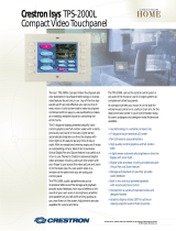
TPS-2000L Shown with Optional Gold Faceplate
4 • 5 Inch Lectern/Wall Mount Touchpanel: TPS-2000L Operations Guide – DOC. 5972A

Crestron Isys
TPS-2000L 5 Inch Lectern/Wall Mount Touchpanel
Physical Views of TPS-2000L Touchpanel
3.07 in
(7.79 cm)
3.43 in
(8.71 cm)
4.76 in
(12.10 cm)
6.73 in
(17.10 cm)
The TPS-2000L touchpanel has 10 engraveable hard buttons (real buttons, not
simulated buttons on the touchpanel membrane), that allow easy access to the most
common functions such as lights, volume, drapes, and screen controls with the added
benefits of touchpanel flexibility incorporated right into one panel. Refer to
““Quick” Pushbuttons” on page 26 for programming information. Custom engraved
keys can be ordered separately by using the Crestron Engraver Software. Version
2.0.0.9 or later is available from the Downloads | Software Updates section of the
Crestron website (www.crestron.com). A photosensor on the front panel permits the
exclusive light-sensing display to switch from daytime super bright to evening soft
glow. The front panel also has an LED that serves as a beacon for the touchpanel
when the screen is in standby mode and the room is dark.
Industry Compliance
As of the date of manufacture, the touchpanel have been tested and found to comply
with specifications for CE marking and standards per EMC and
Radiocommunications Compliance Labelling (N11785).
Operations Guide – DOC. 5972A 5 Inch Lectern/Wall Mount Touchpanel: TPS-2000L • 5

5 Inch Lectern/Wall Mount Touchpanel Crestron Isys
TPS-2000L
NOTE: These devices comply with part 15 of the FCC rules. Operation is subject to
the following two conditions: (1) these devices may not cause harmful interference,
and (2) these devices must accept any interference received, including interference
that may cause undesired operation.
Setup
Network Wiring
NOTE: When installing network wiring, refer to the latest revision of the wiring
diagram(s) appropriate to your specific system configuration, available from the
Downloads | Product Manuals | Wiring Diagrams section of the Crestron website
(www.crestron.com).
When calculating the wire gauge for a particular network run, the length of the run
and the power factor of each network unit to be connected must be taken into
consideration. If network units are to be daisy-chained on the run, the power factor
of each network unit to be daisy-chained must be added together to determine the
power factor of the entire chain. The length of the run in feet and the power factor of
the run should be used in the following resistance equation to calculate the value on
the right side of the equation.
Resistance Equation
R = Resistance (refer to table below).
L = Length of run (or chain) in feet.
PF = Power factor of entire run (or chain).
R <
L x PF
40,000
Where:
The required wire gauge should be chosen such that the resistance value is less than
the value calculated in the resistance equation. Refer to the table after this paragraph.
Wire Gauge Values
RESISTANCE (R) WIRE GAUGE
4
16
6
18
10
20
15
22
13
Doubled CAT5
8.7
Tripled CAT5
NOTE: All network wiring must consist of two twisted-pairs. One twisted pair is
the +24V conductor and the GND conductor and the other twisted pair is the Y
conductor and the Z conductor.
NOTE: When daisy-chaining Cresnet units, strip the ends of the wires carefully to
avoid nicking the conductors. Twist together the ends of the wires that share a pin on
the network connector, and tin the twisted connection. Apply solder only to the ends
of the twisted wires. Avoid tinning too far up the wires or the end becomes brittle.
Insert the tinned connection into the Cresnet connector and tighten the retaining
screw. Repeat the procedure for the other three conductors.
6 • 5 Inch Lectern/Wall Mount Touchpanel: TPS-2000L Operations Guide – DOC. 5972A

Crestron Isys
TPS-2000L 5 Inch Lectern/Wall Mount Touchpanel
NOTE: For larger networks (i.e., greater than 28 network devices), it may become
necessary to add a Cresnet Hub/Repeater (CNXHUB) to maintain signal quality
throughout the network. Also, for networks with lengthy cable runs, it may be
necessary to add a Hub/Repeater after only 20 devices.
Identity Code
Every equipment and user interface within the network requires a unique Cresnet
identity code (Cresnet ID). These codes are recognized by a two-digit hexadecimal
number from 03 to FE. Refer to “Interface Menu” on page 8 for instructions on
setting the unit's Cresnet ID. The Cresnet ID of the unit must match the NET ID
specified in the SIMPL Windows program. Refer to “Setting the Net ID in Device
Settings” on page 18 for information about changing the ID in a SIMPL Windows
program.
Configuring the Touchpanel
NOTE: The only connection required to configure the touchpanel is power. Refer to
“Hardware Hookup” on page 12 for details.
MAIN MENU
This menu can also be obtained via
digital reserved join number, 17242.
To configure the unit, it may be necessary to access a series of setup screens prior to
viewing run-time screens that are loaded into the touchpanel for normal operation.
The MAIN MENU for configuring the touchpanel appears when a finger is held to
the touchscreen as power is applied. Remove your finger when the message "SETUP
MODE" appears on the touchscreen.
Upon entering SETUP MODE, the MAIN MENU, shown to the left, displays four
buttons: Touch Screen Calibration, Exit and Run Program, Setup, and
Diagnostics.
The Exit and Run Program button verifies that all of the setup information has
been saved to EEPROM and displays the main page that has been programmed into
your system. The remaining buttons on the MAIN MENU open other menus, which
are discussed in subsequent paragraphs.
Calibration Menu
CALIBRATION MENU
Calibration of the touchscreen is required if the active touch area of a button does
not coincide with the button's image. Select the Touch Screen Calibration
b
utton to
display the CALIBRATION MENU, shown to the left. The CALIBRATION MENU
offers the choice to initiate calibration with the Perform Calibration button or
return to the previous screen with the Return button. Choose an option by touching
the correct button.
If you proceed to calibrate the touchpanel, the screen displays the message "Touch
Lower Right" centered on the panel with a cross hair in the lower right corner. Touch
the cross hair in the corner of the screen to initiate calibration. Another message,
"Touch Lower Left", appears with a cross hair in the correct corner. Touch the
corner of the screen. A final message, “Touch Upper Left”, appears with a cross hair
in the correct corner. Touch the corner of the screen to conclude calibration and
return to the MAIN MENU.
NOTE: When touching the screen during calibration, be as accurate as possible.
Use the tip of a capped pen or the eraser end of a pencil. To cancel calibration and
return to the CALIBRATION MENU without saving calibration data, create a
Operations Guide – DOC. 5972A 5 Inch Lectern/Wall Mount Touchpanel: TPS-2000L • 7

5 Inch Lectern/Wall Mount Touchpanel Crestron Isys
TPS-2000L
calibration error by touching the screen in an area that is opposite from the instructed
area.
Setup Menu
SETUP MENU
To obtain the SETUP MENU, shown to the left, press the Setup button from the
MAIN MENU. The SETUP MENU offers a series of buttons, which opens
additional menus and displays, which are detailed in subsequent paragraphs. After
setup parameters have been set, select the Return button to return to the MAIN
MENU.
NOTE: For convenience, the current CRESNET ID setting is displayed in the lower
left corner.
NOTE: All touchpanel settings are automatically saved in non-volatile memory.
Interface Menu
INTERFACE MENU
The touchpanel communicates with a control system to activate commands or to
display feedback from components within the system. The communication interface
must be correctly specified or communication will not occur. To set communication
parameters select the Interface
b
utton located on the SETUP MENU and display the
INTERFACE MENU, shown to the left.
The Cresnet network identity number (CRESNET ID) is displayed on the
INTERFACE MENU. CRESNET ID is the two-digit hexadecimal number. The
hexadecimal number can range from 03 to FE and must correspond to the NET ID
set in the SIMPL Windows program of the Cresnet system. Matching IDs between
touchpanel and SIMPL Windows program is required if data is to be successfully
transferred. NET ID for the TPS-2000L is factory set to 03.
Two buttons adjacent to the hexadecimal display, UP and DOWN, increase and
decrease the CRESNET ID by one, respectively.
Select the Return button located on the INTERFACE MENU to return to the
SETUP MENU.
Audio Menu
AUDIO MENU
Audio is a useful feedback tool and it can be used to enhance a custom interface. To
obtain the AUDIO MENU, shown to the left, press the Audio button from the
SETUP MENU. The AUDIO MENU offers a series of buttons, which opens
additional screens and each is detailed in a table after this paragraph. Two of the
buttons on the AUDIO MENU perform a function directly. The Restore Default
Settings button returns all audio parameters to their default settings when the button
is selected. After audio parameters have been set, select the Return button to return
to the SETUP MENU.
8 • 5 Inch Lectern/Wall Mount Touchpanel: TPS-2000L Operations Guide – DOC. 5972A

Crestron Isys
TPS-2000L 5 Inch Lectern/Wall Mount Touchpanel
Audio Setup Details
AUDIO
MENU
BUTTON*
AUDIO
SETUP
SCREEN
DESCRIPTION**
Master 85%
Master
Volume
The volume of all audio types (WAV, line, and key click) is
rectified by Master Volume. If Master Volume is set to 100%, the
volume value for a given audio type is its full value. If Master
Volume is set to 0%, the volume of all audio types is overridden
and the touchpanel is silent. If Master Volume is a percentage
(say 50%), then all audio types can achieve only half their value.
WAV 74%
(On)
WAV
Enable WAV files with the
WAV On
button. The
WAV Off
button
disables this feature. Adjust volume with the
UP
and
DOWN
buttons. Select the
Play WAV File
to sample and adjust the
volume as a pre-loaded WAV file plays.
Line 74% (On) Line
Enable line level audio with the
Line On
button. The
Line Off
button disables this feature. Adjust volume with the
UP
and
DOWN
buttons.
All Audio On
All Audio
Control
It is possible to disable all audio types with the press of single
button. Select the
All Audio On
button to enable audio; select
the
All Audio Off
button to activate global muting.
Key Click
Enabled (Vol.
29%)
Key Click
Enable the key click with the
Click On
button. The
Click Off
button disables this feature. Adjust volume with the
UP
and
DOWN
buttons.
Mic AGC On AGC
The built-in microphone AGC (Automatic Gain Control) mode
can be controlled with two buttons:
Mic Audio AGC On
and
Mic
Audio AGC Off
.
Treble & Bass
(53%)
Treble & Bass
Two
UP
and two
DOWN
buttons allow the treble and bass to be
adjusted independently.
* The button text shown in this column demonstrates the default audio setting for the given button.
The items in parenthesis are also default values, but are seen in subsequent screens.
** Each screen has its own
Return
button to revert back to the AUDIO MENU.
Selected buttons are shown in red text on the touchpanel.
Video
Video Screen
The TPS-2000L can display balanced and unbalanced composite video input
supporting both NTSC/PAL formats. Select the Video button from the SETUP
MENU to display the video screen, shown to the left. The panel has built-in time-
based correction so video and graphics are always stable. The size of the video
window depends on the settings made using VT Pro-e. Use the Zoom button (or its
associated reserved join number, 17123) to zoom in on a region of video (2:1). The
initial zoom is centered on the image (shown as horizontal lines in the illustration).
Touch and drag a finger on the screen to pan to a desired area of the image. Selection
of the Return button (or its associated reserved join number, 17124) in the lower
right corner of the zoomed image returns the display to a 1:1 image. There is a
digital reserved join number (17125) that permits a toggle function for zoom.
The Show Controls button on the video screen offers another screen with a series of
buttons, each is detailed in a table after this paragraph. After video parameters have
been set, select the Return button to return to the SETUP MENU.
Operations Guide – DOC. 5972A 5 Inch Lectern/Wall Mount Touchpanel: TPS-2000L • 9

5 Inch Lectern/Wall Mount Touchpanel Crestron Isys
TPS-2000L
Video Setup Details
VIDEO
SCREEN
BUTTONS
DESCRIPTION*
Brightness
This button allows for an increase (
UP
button) and decrease (
DOWN
button) in
the video image brightness.
Contrast
This button allows for an increase (
UP
button) and decrease (
DOWN
button) in
the video image contrast.
Saturation
This button allows for an increase (
UP
button) and decrease (
DOWN
button) in
the video image saturation.
Hue
This button allows for an increase (
UP
button) and decrease (
DOWN
button) in
the video image hue.
Hide Controls This button returns the display to the video screen.
Default
Touchpanel responds with a prompt, "ARE YOU SURE?" Select
YES!
to reset
video parameters to their defaults**. Select
NO!
to return to the previous
screen.
Return This button reverts back to the SETUP MENU.
* Each screen has its own
Return
button to revert back to the SETUP MENU.
** Video default is 50% for each of the video parameters (brightness, contrast, saturation, and hue).
Screen Settings
SCREEN SETTINGS
SCREEN SETTINGS -
BRIGHTNESS
SCREEN SETTINGS – AUTO
BRIGHTNESS THRESHOLD
Screen brightness, orientation, and quality may need to be adjusted because of
ambient light conditions or personal preference. These screen attributes may be
automatically set via programming or be altered manually by selects made from the
SCREEN SETTINGS display, shown to the left. Press the Screen Settings button
from the SETUP MENU to access this screen. To return to the SETUP MENU and
save screen settings, select the Return button on the SCREEN SETTINGS display.
Screen settings are factory set to Brightness Auto, Orientation Upright, and LCD
Bias 95. Alterations to brightness, orientation, and LCD bias are performed on
subsequent screens after selecting the appropriate button.
BRIGHTNESS
Press the Brightness button to open the SCREEN SETTINGS – BRIGHTNESS
display. Manual controls are located on the left side and automatic controls are
located on the right side. Two buttons, ENABLE and DISABLE, are used to
determine whether the touchpanel brightness is controlled manually or automatically
via thresholds. Select the ENABLE button for automatic settings. Notice that a ‘net’
covers the manual controls on the left. The DISABLE button removes the ‘net’ to
permit manual advancements (use the UP button) and reductions (use the DOWN
button) to the screen brightness.
Choose the SETUP button on the SCREEN SETTINGS – BRIGHTNESS display to
open the SCREEN SETTINGS – AUTO BRIGHTNESS THRESHOLD display,
shown to the left. A photosensor on the front panel permits this exclusive light-
sensing touchpanel to automatically determine if the amount of light sensed exceeds
a set threshold value. This threshold value allows the touchpanel to switch between
daytime super bright (high brightness) and evening soft glow (low brightness)
automatically. The right side of this display shows the CURRENT VALUE as
detected by the photosensor. This value, represented by xxx in the illustration, can
range from 0% (dark) to 100% (very bright). The THRESHOLD VALUE located on
the left side of the display needs to be set to automatically adjust brightness. The
numerical value, represented by xxx in the illustration, can range from 0% (dark) to
100% (very bright). Use the UP and DOWN buttons to increase and decrease the
THRESHOLD VALUE, respectively.
10 • 5 Inch Lectern/Wall Mount Touchpanel: TPS-2000L Operations Guide – DOC. 5972A

Crestron Isys
TPS-2000L 5 Inch Lectern/Wall Mount Touchpanel
If the CURRENT VALUE has exceeded the THRESHOLD VALUE, the screen
switches to high brightness. When the CURRENT VALUE is less than the
THRESHOLD VALUE, the screen switches to low brightness.
ORIENTATION
SCREEN SETTINGS -
ORIENTATION
There is no ‘top’ or ‘bottom’ when installing the TPS-2000L. Press the Orientation
button to open the SCREEN SETTINGS – ORIENTATION display, shown to the
left. This setup feature allows the orientation of the display to be rotated 180° with
the press of a button. Therefore, if the touchpanel was inadvertently installed upside
down, the display can be rotated without removing the unit from the mounting
surface. However, keep in mind that the best viewing angle is seen from the top
when the orientation of the screen is set to Upright.
Two buttons, Right Side Up and Up Side Down, are used to set the orientation of
the screen. The selected button appears in red text. By definition, the Right Side Up
button displays the screen with connectors at the bottom of the touchpanel and as a
result, the term Orientation Upright appears on the SCREEN SETTINGS display’s
center button. The Up Side Down button displays the screen with connectors at the
top of the touchpanel and the term Orientation Inverted appears on the SCREEN
SETTINGS display’s center button. Use the Return button to get back to the
SCREEN SETTINGS display.
NOTE: Whether the touchpanel screen orientation is set to Upright or Inverted the
sequence of digital join numbers (1 through 5 on the left side and 6 through 10 on the
right side) is consistent.
LCD BIAS
SCREEN SETTINGS – LCD BIAS
The quality of the image displayed on the touchpanel can be adjusted from the
SCREEN SETTINGS - LCD BIAS display, which appears after selecting the LCD
Bias button from the SCREEN SETTINGS display. To adjust the quality, examine
the box containing horizontal lines on the SCREEN SETTINGS - LCD BIAS
display. If the lines in the box flicker, use the UP and DOWN buttons to eliminate
the flicker. If the lines appear without flicker, no adjustments are necessary.
Adjustments can range between 1 and 255. Typically, the quality of the image is best
when the LCD bias is set between 90 and 110 (default is 105). Use the Return
button to get back to the SCREEN SETTINGS display.
Night Light Settings
NIGHT LIGHT SETTINGS
An LED on the front panel (same end as the two connectors) serves as a beacon for
the touchpanel. When activated, it allows a user to find the touchpanel in standby
mode in a completely dark room. Press the Night Light button on the SETUP
MENU to open the NIGHT LIGHT SETTINGS display, shown to the left. Four
buttons, Turn Night Light Off, Select Low Brightness, Select Medium
Brightness, and Select High Brightness, are used to determine whether the night
light is off or on with some preset brightness. The selected button appears in red text
with slightly altered wording. To return to the SETUP MENU and save the night
light setting, select the Return button. Notice that the state of the night light setting
is shown on the Night Light button on the SETUP MENU.
Operations Guide – DOC. 5972A 5 Inch Lectern/Wall Mount Touchpanel: TPS-2000L • 11

5 Inch Lectern/Wall Mount Touchpanel Crestron Isys
TPS-2000L
Timeout Menu
TIMEOUT SETTINGS
The touchpanel display can be turned off (standby mode) when not in active use.
Select the Timeout button on the SETUP MENU to reveal the TIMEOUT
SETTINGS display, shown to the left. This setting turns the display off when the
touchpanel is inactive for a specified time. Touch the screen to awaken the
touchpanel and the last screen to be displayed reappears. The time value, re
p
resented
by xxx in the illustration, can range from 0 (disables the timeout) to 120 (minutes).
Two buttons, UP and DOWN, increase and decrease the timeout, respectively.
Select the Return button to save the timeout setting and return to the SETUP
MENU.
Diagnostics Menu
DIAGNOSTICS MENU
The Diagnostics button from the MAIN MENU should only be used under
supervision from a Crestron customer service representative during telephone
support. The options available from the DIAGNOSTICS MENU, shown to the left,
are numeric in nature and their interpretation is beyond the scope of this manual.
NOTE: The “About…” button will display a screen indicating the current version
of firmware residing on the touchpanel.
Hardware Hookup
CAUTION: Do not remove the tape that covers the photosensor. Doing so can short
the board and damage the touchpanel.
CAUTION: Do not apply excessive pressure to the touchscreen display during
handling (mounting/installation). Doing so can crack the screen and damage the
touchpanel.
Make the necessary connections as called out in the illustration that follows this
paragraph. Refer to “Network Wiring” on page 6 before attaching the 4-pin
connector. Apply power last.
Hardware Connections for the TPS-2000L (Back of the Unit is Shown)
CONNECTS
TO
CONTROL
SYSTEM
CONNECTS TO
AUDIO SOURCE,
MICROPHONE,
VIDEO SOURCE
12 • 5 Inch Lectern/Wall Mount Touchpanel: TPS-2000L Operations Guide – DOC. 5972A

Crestron Isys
TPS-2000L 5 Inch Lectern/Wall Mount Touchpanel
5
8-PIN CONNECTOR (Top View)
1234 76 8
The 8-pin connector on the unit provides balanced/unbalanced audio and video
(supporting both NTSC/PAL formats). Refer to the pinout after this paragraph for
details. The left most columns provide a signal name for each pin. For a balanced
audio/video system refer to the BALANCED AUDIO & VIDEO column centered
in the table. Balanced video format is typically used when distributing video via
CAT 5 (i.e., from a Crestron CNX-PVID8x3 or 8x4). To obtain unbalanced audio or
video, attach jumpers to designated pins and make connections as described in the
three right-most columns. Unbalanced video format is typically used when
distributing video via coaxial cable. Mixed systems (i.e., balanced audio with
unbalanced video and unbalanced audio with balanced video) are permitted; only
make those connections that are necessary.
NOTE: Distribution of balanced video should not exceed 500 feet (152.4 meters)
and the distribution for unbalanced video should not exceed 100 feet (30.5 meters).
For distances greater than these specified lengths use a distribution amplifier.
Pinout Connections for the TPS-2000L
PIN
SIGNAL
NAME
BALANCED
AUDIO &
VIDEO
UNBALANCED
AUDIO IN
*
UNBALANCED
AUDIO OUT
UNBALANCED
VIDEO
**
1 Audio In + Audio In + Audio In +
2 Audio In - Audio In - Audio Ground
3
Ground/
Shield
N/C Audio Ground
4 Mic Out + Mic Out + Mic Out +
5 Mic Out - Mic Out - N/C
6
Ground/
Shield
N/C Mic Ground Video Ground
7 Video In + Video In + Video In +
8 Video In - Video In - Video Ground
where N/C = No Connection * Jumper pins 2 & 3 ** Jumper pins 6 & 8
NOTE: Balanced sources can be received from CNX-PVID (video), CNX-BIPAD
(audio), or CNXRMCLV (audio and video) devices.
Mounting Options
The TPS-2000L touchpanel installs simply and cleanly into existing or newly
constructed walls, with an assortment of pre- and post-construction mounting
options. All mounting options are provided separately from the actual touchpanel.
Refer to the table after this paragraph for a complete list of mounting options and
respective Installation Guides for the TPS-2000L.
NOTE: Observe the procedure in the respective Installation Guide and mount the
touchpanel to a surface with one of the many mounting options. A cutout measuring
6
3
/
8
" (16.159 cm) wide by 4
7
/
16
" (11.283 cm) high can safely be made into the
mounting surface for all applications. Depending on which mounting option is
chosen, some trimming of the cutout may need to be done during installation. For
exact cutout measurements, consult the latest revision of the applicable Installation
Guides listed in the following table.
Operations Guide – DOC. 5972A 5 Inch Lectern/Wall Mount Touchpanel: TPS-2000L • 13

5 Inch Lectern/Wall Mount Touchpanel Crestron Isys
TPS-2000L
Mounting Options for the TPS-2000L
PRE-CONSTRUCTION
*
OPTION
POST-CONSTRUCTION
**
OPTION
MODEL
NUMBER
DOCUMENT
NUMBER
Back Box Kit - BB-2000L 5973
Pre-Construction Mount Kit - PMK-2000L 6018
Mud Mount Kit (accessory) - MMK-2000L 6025
Trim Mount Kit (accessory) - TMK-2000L 6026
- Wall Mount Kit - Mud WMKM-2000L 6025
- Wall Mount Kit - Trim WMKT-2000L 6026
- Water Resistant Cover TPS-WPK 5993
* Pre-construction refers to framed walls prior to hanging drywall.
** Post-construction refers to framed walls with drywall hung.
If the BB-2000L or PMK-2000L are to be used and a touchpanel is not available, the
installer can either leave the hole in the mounting surface open (if permitted by local
building codes) or attach the cover plate supplied with the mounting kit.
Touchpanel Mounting
Required Tools
#1 Phillips tip screwdriver
1. If the cover plate is attached, use a #1 Phillips screwdriver to loosen and
remove the four screws and plate.
2. Connect all required cables to the touchpanel.
3. Insert the touchpanel (without its faceplate) into the mounting option and
align the four screw holes.
4. Insert and tighten the four supplied screws (finger tight and then using a #1
Phillips screwdriver, tighten an additional 1/8-turn).
5. Insert the ten buttons. If the buttons are engraved, verify that the placement
of the each button matches the programming.
6. Cover the mounted unit with the faceplate. Refer to the illustration after this
paragraph for guidance.
14 • 5 Inch Lectern/Wall Mount Touchpanel: TPS-2000L Operations Guide – DOC. 5972A

Crestron Isys
TPS-2000L 5 Inch Lectern/Wall Mount Touchpanel
Exploded View for Mounting the TPS-2000L in the Optional BB-2000L Back Box
TPS-2000L
BB-2000L
#6-32 x 1
1
2
" (SR-06-32-1R5000-2)
PAN HEAD SCREW, QTY. 4
SUPPLIED BY CRESTRON
The stylish, elegant design accommodates painting and custom laser engraving of its
faceplate and keys. There are even plastic faceplates that accept metal and non-metal
inlays for that custom contemporary appearance. Call a Crestron customer support
representative for the specific details.
Optional custom engraved keys can be ordered separately by using the Crestron
Engraver Software. Version 2.0.0.9 or later is available from the Downloads |
Software Updates section of the Crestron website (www.crestron.com
).
NOTE: If it is necessary to remove the touchpanel, secure and label the attached
cables before disconnecting them from the back of the touchpanel.
Touchpanel Removal
If it is necessary to remove the touchpanel after it has been installed into a mounting
surface, complete the following steps in the order provided to remove the
touchpanel. The only tool required is a #1 Phillips tip screwdriver.
1. Lift the plastic cover off the touchpanel.
2. Remove the plastic buttons from the touchpanel. If buttons are
engraved, be sure to record button engraving with button location so
that the buttons can be properly returned.
Operations Guide – DOC. 5972A 5 Inch Lectern/Wall Mount Touchpanel: TPS-2000L • 15

5 Inch Lectern/Wall Mount Touchpanel Crestron Isys
TPS-2000L
3. Loosen and remove four screws that secure touchpanel to mounting
option.
4. Using equal pressure, carefully remove the touchpanel from the
opening.
5. If necessary, secure attached cables before disconnecting them from the
back of the touchpanel.
Recommended Cleaning
Keep the surface of the touchscreen free of dirt, dust, or other materials that could
degrade optical properties. Long term contact with abrasive materials can scratch the
surface, which may detrimentally affect image quality.
For best cleaning results, use a clean, damp, non-abrasive cloth with any
commercially available non-ammonia glass cleaner. Bezels may not provide a
complete watertight seal. Therefore, apply cleaning solution to the cloth rather than
the surface of the touchscreen. Wipe touchscreen clean and avoid ingress of moisture
beneath panels.
Programming Software
Have a comment about
Crestron software?
Direct software related suggestions
and/or complaints to Crestron via
email (software@crestron.com)
.
Do not forward any queries to this
address. Instead refer to “Further
Inquiries” on page 38 for assistance.
Setup is easy thanks to Crestron’s Windows
-
b
ased programming software. Crestron
Application Builder™ (AppBuilder) creates a complete project, with no special
programming required. Crestron AppBuilder completes all necessary programming
for a base system including all touchpanel screens and the control system program.
Once Crestron AppBuilder creates the project, the system interfaces and program
logic can be customized. It can easily be modified with Crestron development tools
(i.e., SIMPL Windows and Crestron VisionTools
Pro-e (VT Pro-e) software
packages).
The program output of Crestron AppBuilder is a SIMPL Windows program with
much of the functionality encapsulated in macros. Therefore, extending the
capabilities of the system is very easy. Crestron AppBuilder and SIMPL Windows
are intended for users with different levels of programming knowledge. Crestron
AppBuilder is easier to use for the beginning programmer, and much faster for all
programmers. However, it does not allow the degree of control and flexibility that
SIMPL Windows does. Of course, one can initiate programming using the easiest
method (Crestron AppBuilder) and use advanced techniques that are available from
SIMPL Windows to customize the job.
Crestron AppBuilder comes with templates for all supported interfaces. If a user
wishes to create a touchpanel project using templates with a different look-and-feel
this can be accomplished by making a custom template. This custom template can
then be used by Crestron AppBuilder to create the final project files to be loaded into
the panels. Alternatively, VT Pro-e can be used to tweak projects created with
Crestron AppBuilder or develop original touchpanel screen designs.
The following are recommended software version requirements for the PC:
• Application Builder version 1.1.6 or later with Application Builder
Templates version 2.12 or later. Requires SIMPL Windows.
• SIMPL Windows version 2.02.11 or later with library update file 143.
Requires SIMPL+ Cross Compiler version 1.1.
• Crestron Database version 15.8.6 or later. Required by SIMPL Windows.
16 • 5 Inch Lectern/Wall Mount Touchpanel: TPS-2000L Operations Guide – DOC. 5972A
/