Page is loading ...

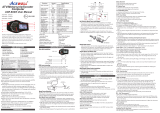
Power/Signal Diagram
Power/Signal Action
1. The flywheel spins, driving the AC generator inside the flywheel. Power from the
AC generator goes to the drive board.
2. The drive board converts this power into VDC for use by other components, such
as the display and the magnet.
4. Power travels to the hub board then to the display through the data cable.
5. When the user presses a command key, the display main program IC emits a
signal that travels down the data cable to the drive board. The drive board puts out
or stops putting out power in response to display commands.
For wiring or voltage specifications, tur n to the following:
A. Drive Board Cable Connections: Page 2
B. Drive Board LEDs: Page 2
C. Voltage Specs at Drive Board: Page 3
D. Display Power Test: Page 4
E. Speed Sensor Test: Page 4
F. Resistance Operation and Troubleshooting: Page 5
Drive Board
Magnet &
Reed Switch
Display Board
Data
Cable
Key
Power:
Signal:
Speed Sensor
Resistance
Electro-
Magnet
Generator
VDC
Batter y
VAC
C52R/C52U C53R/C53U Bike Troubleshooting Notes - April 20, 2004
Page 1

Cable Connectors
A. .
B. To reed switch: black, black; Conductivity when magnet passes reed
switch;
C. To 6 VDC battery: black, red. Measure about 6.4 VDC when charging,
about 6 VDC when discharging.
D. 3A Fuse
E.
F. To magnet: white, black. The higher the resistance, the higher the
voltage output.
See chart below.
LEDs
CLK: Flashes to indicate incoming speed sensor signal from reed switch
and battery.
CHARGE: Lights when battery is being recharged; Color: yellow-green.
PWR: Lights when generator provides power. Color: yellow-green.
Data cable to hub board, then to display
Incoming power wires: white, green, black. Voltage varies according
to speed. The faster, the more voltage. See chart below.
A
B
C
D
E
CLK
PWR
Charge
A. Drive Board Cable Connectors
B. Drive Board LEDs
Page 2
C52R/C52U C53R/C53U Bike Troubleshooting Notes - April 20, 2004
F

C. Voltage Specs at Drive Board
Page 3
AC Generator Voltage to Drive Board
Resistance 1 Speed 60 SPM 80 VAC
Resistance 1 Speed 70 SPM 90 VAC
Resistance 1 Speed 80 SPM 100 VAC
Resistance 1 Speed 90 SPM 115 VAC
Resistance 1 Speed 100 SPM 130 VAC
(Approximate voltages shown. Actual readings will vary slightly.)
Voltage from Drive Board to Electro-Magnet
Speed 60 SPM Level 1 5 VDC
Speed 60 SPM Level 5 7 VDC
Speed 60 SPM Level 10 9 VDC
Speed 60 SPM Level 15 11 VDC
Speed 20 SPM Level 20 12 VDC
Voltage from Drive Board to Batter y
Recharging: 6.4 VDC
Battery Voltage Spec: 6 VDC
(Approximate voltages shown. Actual readings will vary slightly.)
C52R/C52U C53R/C53U Bike Troubleshooting Notes - April 20, 2004

D. Display Power Test
The display does not have a power indicator LED. If the display LEDs don't
light, detect power to the display by placing probes on the capacitor near
the data cable. Normal reading: 5 VDC. If there is power here but the LEDs
don't light, replace the display board. If there is no voltage here, inspect
the data cable and drive board.
E. Speed Sensor Test
Operation
As the drive pulley rotates, a reed switch passes a magnet. Each time the
reed switch passes the magnet, the circuit is closed, creating a signal to
the display. The display main IC translates this signal into the speed and
distance readout.
a voltmeter to the audible continuity setting.
Symptom of Malfunction
A sign of a failing speed sensor circuit is no speed and distance on the
display. Resistance is also lost. The display could black out altogether.
Troubleshooting
1. LED test: Rotate the drive pulley so the magnet and reed switch pass by
each other. Normal: CLK LED on the drive board lights when the magnet
and reed switch pass by each other.
2. Voltmeter test: Put Place
probes on the two speed sensor wires. Rotate the drive pulley so the reed
switch passes by the magnet. Normal: The meter beeps, indicating
continuity, when the magnet and reed switch meet. This indicates that the
magnet/reed switch are OK.
3. Test the magnet by seeing if it attracts metal.
4. If the magnet or reed switch fail these tests, replace it.
Note: C51, C52, C53 bikes have two magnets on the drive pulley.
Page 4
C52R/C52U C53R/C53U Bike Troubleshooting Notes - April 20, 2004

F. Resistance Operation and Troubleshooting
Operation
1. When the user presses key commands, signals travel from the display
to the drive board. In recumbent bikes, the signal goes through a hub
board.
2. The drive board puts out power to the magnet. The higher the voltage,
the higher the attraction to the metal flywheel, the greater the resistance.
Symptom of Malfunction
1. Resistance doesn't change when the user presses a resistance
command key or the resistance should change in a program.
Troubleshooting
1. Inspect whether the drive board puts out power to the magnet.
Specifications are shown on page . If the drive board puts out power to the
magnet, then the drive board, display, etc., is good. Inspect the magnet.
2. Do an OHM test on the magnet. Put voltmeter on OHM setting.
Disconnect magnet wire to the wire from the drive board. Place one probe
on each pin of the magnet wires. Normal reading: 11 OHM. If much lower
than this, replace the magnet.
C52R/C52U C53R/C53U Bike Troubleshooting Notes - April 20, 2004
Page 5

Fuse
On/Off
Switch
Transfor mer
Drive Board
Magnet &
Reed Switch
Display Board
VR
Motor
Power cord & plug
Data
Cable
Key
Power:
Signal:
Spor tsAr t Bike Power/Signal Flow Char t
506P/508P/C51U/C51R
Resistance
Speed Sensor

Fuse
On/Off
Switch
Transfor mer
Drive Board
Display Board
Power cord & plug
Data
Cable
Key
Power:
Signal:
Spor tsAr t Bike Power/Signal Flow Char t
5002B/5005B
Speed Sensor
Resistance
Electro-
Magnet
Optic Sensor

Generator
Drive Board
Display Board
Data
Cable
Key
Power:
Signal:
Spor tsAr t Bike Power/Signal Flow Char t
5100/5150/5200
Optic Sensor
Speed Sensor
Electro-
Magnet
Resistance
Note: The diagram for 5002/5005 would be similar except for two major
differences: 5002/5005 have a generator in the flywheel that produces
AC power, and they don't have an optic sensor. They use the wave
frequency instead of an optic sensor.
VDC
Batter y
/