
MTM800
with Enhanced Control Head
TETRA Mobile Terminal
380–430 MHz (MT912M)
410–470 MHz (MT512M)
Basic Service Manual
Part Number: 6866539D28-D
*6866539D28*

COPYRIGHT
Copyrights
© 2001–2009 by Motorola Inc. All rights reserved.
No part of this manual may be reproduced, transmitted, stored in a retrieval system, or
translated into any language or computer language, in any form or by any means, without
the prior written permission of Motorola Inc.
Computer Software Copyrights
The Motorola products described in this manual may include copyrighted Motorola
computer programs stored in semiconductor memories or other media. Laws in the United
States and other countries preserve for Motorola certain exclusive rights for copyrighted
computer programs including, but not limited to, the exclusive right to copy or reproduce in
any form the copyrighted computer program. Accordingly, any copyrighted Motorola
computer programs contained in the Motorola products described in this manual may not
be copied, reproduced, modified, reverse-engineered, or distributed in any manner without
the express written permission of Motorola. Furthermore, the purchase of Motorola
products shall not be deemed to grant either directly or by implication, estoppel, or
otherwise, any license under the copyrights, patents or patent applications of Motorola,
except for the normal non-exclusive license to use that arises by operation of law in the sale
of a product.
Trademarks
Motorola, the Motorola Logo and all other trademarks identified as such herein are
trademarks of Motorola Inc. All other product or service names are the property of their
respective owners.

DOCUMENT HISTORY i
DOCUMENT HISTORY
The following major changes have been implemented in this manual since the previous edition::
Edition Description Date
6866539D28-A Initial Release Mar. 2007
6866539D28-B Changes in Accessories.
Included info on MACE UCM Board Kit.
Aug. 2007
6866539D28-C Added GPS – Sirf Module Kit info
Updated parts lists and exploded views
Jan. 2008
6866539D28-D Updated service kits Aug. 2009

ii
Notes

Product Safety and RF Exposure iii
Product Safety and RF Energy Exposure
for TETRA Mobile Terminals
installed in Vehicles or as Fixed Site Control Stations
The information provided in this document supersedes information contained in user guides,
manuals and other documentation published prior to February 2002.
RF Energy Exposure Awareness and Control Information, and Operational
Instructions for FCC Occupational Use Requirements.
Note: This terminal is intended for use in occupational / controlled conditions, where users have full
knowledge of their exposure and can exercise control over their exposure to meet FCC/ICNIRP
limits. This terminal device is NOT authorized for general population, consumer or any other use.
This 2-way terminal uses electromagnetic energy in the radio frequency (RF) spectrum to provide
communications between two or more users over a distance. It uses radio frequency (RF) energy or
radio waves to send and receive calls. RF energy is one form of electromagnetic energy. Other
forms include, but are not limited to, sunlight and x-rays. RF energy, however, should not be
confused with these other forms of electromagnetic energy, which when used improperly, can cause
biological damage. Very high levels of x-rays, for example, can damage tissues and genetic
material.
Experts in science, engineering, medicine, health and industry work with organisations to develop
standards for safe exposure to RF energy. These standards provide recommended levels of RF
exposure for both workers and the general public. These recommended RF exposure levels include
substantial margins of protection.
All Motorola 2-way terminals are designed, manufactured and tested to ensure they meet
government-established RF exposure levels. In addition, manufacturers also recommend specific
operating instructions to users of 2-way terminals. These instructions are important because they
inform users about RF energy exposure and provide simple procedures on how to control it.
Please refer to the following Web sites for more information on what RF energy exposure is and how
to control your exposure to assure compliance with established RF exposure limits.
http://www.fcc.gov/oet/rfsafety/rf-faqs.html
http://www.osha.gov/SLTC/radiofrequencyradiation/index.html
THIS CHAPTER IS AN EXTRACT OF THE MULTI LINGUAL MOBILE SAFETY
BOOKLET PUBLICATION No. 6866537D37_.
FOR THE LATEST SAFETY INFORMATION REFER TO THE SEPARATE SAFETY
BOOKLET DELIVERED WITH YOUR TERMINAL.
BEFORE USING THIS TERMINAL READ THIS INFORMATION WHICH
CONTAINS IMPORTANT OPERATING INSTRUCTIONS FOR SAFE USAGE AND
RF ENERGY AWARENESS AND CONTROL INFORMATION FOR COMPLIANCE
WITH RF ENERGY EXPOSURE LIMITS IN APPLICABLE NATIONAL AND
INTERNATIONAL STANDARDS.
!
C a u t i o n

iv Product Safety and RF Exposure
Federal Communications Commission Regulations (US markets only)
The FCC rules require manufacturers to comply with the FCC RF energy exposure limits for mobile
2-way terminals before they can be marketed in the U.S. When 2-way terminals are used as a
consequence of employment, the FCC requires users to be fully aware of and able to control their
exposure to meet occupational requirements. Exposure awareness can be facilitated by the use of a
label directing users to specific user awareness information. Your Motorola 2-way terminal has an
RF exposure product label. Do not remove this RF exposure label from the device. Also, your
Motorola user manual, or separate safety booklet, includes information and operating instructions
required to control your RF exposure and to satisfy compliance requirements.
Compliance with RF Exposure Standard
Your Motorola terminal is designed and tested to comply with a number of national and international
standards and guidelines (listed below) regarding human exposure to radio frequency
electromagnetic energy. This terminal complies with IEEE and ICNIRP exposure limits for
occupational/controlled RF exposure environments at duty factors of up to 50% talk–50% listen
and is authorised by the IEEE/ICNIRP for occupational use. In terms of measuring RF energy for
compliance with these exposure guidelines, your terminal antenna radiates measurable RF energy
only while it is transmitting (during talking), not when it is receiving (listening) or in standby mode.
Your Motorola two-way terminal complies with the following RF energy
exposure standards and guidelines:
• United States Federal Communications Commission, Code of Federal Regulations; 47 CFR part
2 sub-part J
• American National Standards Institute (ANSI) / Institute of Electrical and Electronic Engineers
(IEEE) C95. 1-1992
• Institute of Electrical and Electronic Engineers (IEEE) C95.1-1999 Edition
• International Commission on Non-Ionizing Radiation Protection (ICNIRP) 1998
• Ministry of Health (Canada) Safety Code 6. Limits of Human Exposure to Radiofrequency
Electromagnetic Fields in the Frequency Range from 3 kHz to 300 GHz, 1999
• Australian Communications Authority Radiocommunications (Electromagnetic Radiation -
Human Exposure) Standard 2003
• ANATEL, Brasil Regulatory Authority, Resolution 256 (April 11, 2001) “additional requirements for
SMR, cellular and PCS product certification.”

Product Safety and RF Exposure v
RF Exposure Compliance and Control Guidelines and Operating Instructions
To control exposure to yourself and others and to ensure compliance with the RF exposure limits,
always adhere to the following procedures.
Guidelines:
• User awareness instructions should accompany device when transferred to other users.
• Do not use this device if the operational requirements described herein are not met.
Instructions:
• Transmit no more that the rated duty factor of 50% of the time. To transmit (talk), push the
Push-To-Talk (PTT) button. To receive calls, release the PTT button. Transmitting 50% of the
time, or less, is important because this terminal generates measurable RF energy exposure only
when transmitting (in terms of measuring for standards compliance).
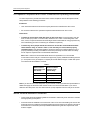
• Transmit only when people outside the vehicle are at least the recommended minimum
lateral distance away, as shown in Table 1, from the body of a vehicle with a properly
installed antenna. This separation distance will ensure that there is sufficient distance from a
properly installed (according to installation instructions) externally-mounted antenna to satisfy
the RF exposure requirements in the standards listed above.
Note: Table 1 lists the recommended lateral distance for bystanders in an uncontrolled
environment from the body of a vehicle with an approved, properly installed transmitting antenna
(i.e. monopoles over a ground plane, or dipoles) at several different ranges of rated radio power
for mobile terminals installed in a vehicle.
Note: If you are not sure of the rated power of your terminal, contact your Motorola representative or
dealer and supply the terminal model number found on the terminal model label. If you cannot
determine the rated power out, then assure 90cms (3 feet) separation from the body of the vehicle.
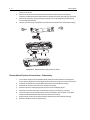
Mobile Antenna Installation Guidelines
• These mobile antenna installation guidelines are limited to metal body motor vehicles or vehicles
with appropriate ground planes.
• Antennas should be installed in the centre area of the roof or the trunk lid taking into account the
bystander exposure conditions of backseat passengers and according to the specific instructions
and restrictions in the Radio (Terminal) Installation Manual along with the requirements of the
antenna supplier.
Table 1
Mobile terminal
Rated Power (see
Note below)
Minimum Lateral
Distance From
Vehicle Body
Less than 7 Watts 20 cm (8 Inches)
7 to 15 Watts 30 cm (1 Ft)
16 to 39 Watts 60 cm (2 Ft)
40 to 110 Watts 90 cm (3 Ft)

vi Product Safety and RF Exposure
• Trunk lid installations are limited to vehicles with clearly defined flat trunk lids, and in some
cases, to specific terminal models and antennas. See the Radio (Terminal) Installation Manual
for specific information on how and where to install specific types of approved antennas to
facilitate recommended operating distances to all potentially exposed persons.
• Use only Motorola-approved supplied antenna or a Motorola approved replacement
antenna. Unauthorised antennas, modifications, or attachments could damage the terminal and
may result in non-compliance with RF Safety Standards.
Approved Accessories
• This terminal has been tested and meets the RF Safety Standards when used with the Motorola
accessories supplied or designated for this product. Use of other accessories may result in non-
compliance with RF Safety Standards.
• For a list of Motorola approved antennas, please see your dealer or local Motorola contact. Your
nearest dealer can be found at the following web site:
http://www.motorola.com/governmentandenterprise
Additional Information
• For additional information on exposure requirements or other training information, visit
http://www.motorola.com/rfhealth
Compliance and Control Guidelines and Operating Instructions for Mobile
Two-Way Terminals Installed as Fixed Site Control Stations
If mobile terminal equipment is installed at a fixed location and operated as a control station or as a
fixed unit, the antenna installation must comply with the following requirements in order to ensure
optimal performance and compliance with the RF energy exposure limits in the standards and
guidelines listed on previous page:
• The antenna should be mounted outside the building on the roof or a tower if at all possible.
• As with all fixed site antenna installations, it is the responsibility of the licensee to manage the
site in accordance with applicable regulatory requirements and may require additional
compliance actions such as site survey measurements, signage, and site access restrictions in
order to insure that exposure limits are not exceeded.
Electromagnetic Interference/Compatibility
Note: Nearly every electronic device is susceptible to electromagnetic interference (EMI) if
inadequately shielded, designed or otherwise configured for electromagnetic compatibility. It may be
necessary to conduct compatibility testing to determine if any electronic equipment used in or
around vehicles or near fixed site antenna is sensitive to external RF energy or if any procedures
need to be followed to eliminate or mitigate the potential for interaction between the terminal
transmitter and the equipment or device.

Product Safety and RF Exposure vii
Facilities
To avoid electromagnetic interference and/or compatibility conflicts, turn off your terminal in any
facility where posted notices instruct you to do so. Hospitals or health care facilities may be using
equipment that is sensitive to external RF energy.
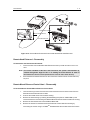
Vehicles
To avoid possible interaction between the terminal transmitter and any vehicle electronic control
modules, such as, ABS, engine, or transmission controls, the terminal should be installed only by an
experienced installer and that the following precautions be used when installing the terminal:
1. Refer to the manufacturer’s instructions or other technical bulletins for recommendations on
terminal installation.
2. Before installing the terminal, determine the location of the electronic control modules and their
harnesses in the vehicle.
3. Route all terminal wiring, including the antenna transmission line, as far away as possible from
the electronic control units and associated wiring.
Driver Safety
Check the laws and regulations on the use of terminals in the area where you drive. Always obey
them. When using your terminal while driving, please:
• Give full attention to driving and to the road.
• Pull off the road and park before making or answering a call if driving conditions so require.

viii Product Safety and RF Exposure
OPERATIONAL WARNINGS
For Vehicles With Air Bags
Do not mount or place a mobile terminal in the area over an air bag or in the air bag deployment
area. Air bags inflate with great force. If a terminal is placed in the air bag deployment area and
the air bag inflates, the terminal may be propelled with great force and cause serious injury to
occupants of the vehicle.
Potentially Explosive Atmospheres
Turn off your terminal prior to entering any area with a potentially explosive atmosphere. Sparks
in a potentially explosive atmosphere can cause an explosion or fire resulting in bodily injury or
even death.
The areas with potentially explosive atmospheres referred to above include fuelling areas such
as below decks on boats, fuel or chemical transfer or storage facilities, areas where the air
contains chemicals or particles, such as grain, dust or metal powders. Areas with potentially
explosive atmospheres are often but not always posted.
Blasting Caps And Blasting Areas
To avoid possible interference with blasting operations, turn off your terminal when you are near
electrical blasting caps, in a blasting area, or in areas posted:
"Turn off two-way radio (terminal)". Obey all signs and instructions.
For terminals installed in vehicles fueled by liquefied petroleum gas, refer to the (U.S.) National
Fire Protection Association standard, NFPA 58, for storage, handling, and/or container
information. For a copy of the LP-gas standard, NFPA 58, contact the National Fire Protection
Association, One Battery Park, Quincy, MA.
!
W A R N I N G
!

Product Safety and RF Exposure ix
Only specialized workshops should be contacted for installation, maintenance and repair work.
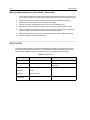
This unit is equipped with protection fuses in the Power and Ignition Sense Cable.
Replace these fuses only with the original ratings!
Caution: Failure to use correct manufactures approved parts
may result in physical damage to this unit.
Fuse for Power Cable GKN6270/GKN6274: 10A (Motorola Part Number: 65C80283E05)
Fuse for Ignition Sense Cable HKN9327: 4A (Motorola Part Number: 65C80283E02)
ADDITIONAL IMPORTANT INFORMATION
FOR SERVICING AND INSTALLING THE TERMINAL
!
C a u t i o n
Installations, Wartungs- und Reparaturarbeiten dürfen ausschließlich von autorisiertem und geschultem
Personal ausgeführt werden.
Dieses Gerät ist mit einer Schutzsicherung im Stromversorgungskabel ausgestattet.
Bei Austausch ausschließlich den Originalwert verwenden
WARNUNG: Bei Einsetzen von nicht vom Hersteller freigegebenen Ersatzteilen
kann das Gerät zerstört werden.
Sicherung für Stromversorgungskabel GKN6270/GKN6274: 10A (Motorola Best.-Nr.:65C80283E05)
Sicherung für Zündungserkennungskabel HKN9327: 4A (Motorola Best.-Nr.:65C80283E02)
ZUSÄTZLICHE SICHERHEITSINFORMATIONEN FÜR
SERVICE UND INSTALLATION DES FUNKGERÄTES
!
Achtung

x
Notes

CONTENTS xi
CONTENTS
COPYRIGHT
Copyrights . . . . . . . . . . . . . . . . . . . . . . . . . . . . . . . . . . . . . . . . . . . . . . . . . . . . . . . . . . .ii
Computer Software Copyrights . . . . . . . . . . . . . . . . . . . . . . . . . . . . . . . . . . . . . . . . . . ii
Trademarks . . . . . . . . . . . . . . . . . . . . . . . . . . . . . . . . . . . . . . . . . . . . . . . . . . . . . . . . . . .ii
DOCUMENT HISTORY . . . . . . . . . . . . . . . . . . . . . . . . . . . . . . . . . . . . . . . . . . . . . . . . . . . i
RF Energy Exposure Awareness and Control Information. . . . . . . . . . . . . . . . . . . . . iii
Federal Communications Commission Regulations (US markets only). . . . . . . . . . . iv
Compliance with RF Exposure Standard . . . . . . . . . . . . . . . . . . . . . . . . . . . . . . . . . . iv
RF Exposure Compliance and Control Guidelines and Operating Instructions . . . . . v
Mobile Antenna Installation Guidelines . . . . . . . . . . . . . . . . . . . . . . . . . . . . . . . . . . . v
Approved Accessories . . . . . . . . . . . . . . . . . . . . . . . . . . . . . . . . . . . . . . . . . . . . . . . . vi
Additional Information . . . . . . . . . . . . . . . . . . . . . . . . . . . . . . . . . . . . . . . . . . . . . . . . vi
Compliance and Control Guidelines and Operating Instructions for Mobile Two-Way
Terminals Installed as Fixed Site Control Stations. . . . . . . . . . . . . . . . . . . . . . . . . . . vi
Electromagnetic Interference/Compatibility . . . . . . . . . . . . . . . . . . . . . . . . . . . . . . . . vi
Facilities . . . . . . . . . . . . . . . . . . . . . . . . . . . . . . . . . . . . . . . . . . . . . . . . . . . . . . . . . . . vii
Vehicles . . . . . . . . . . . . . . . . . . . . . . . . . . . . . . . . . . . . . . . . . . . . . . . . . . . . . . . . . . . vii
Driver Safety . . . . . . . . . . . . . . . . . . . . . . . . . . . . . . . . . . . . . . . . . . . . . . . . . . . . . . . vii
OPERATIONAL WARNINGS . . . . . . . . . . . . . . . . . . . . . . . . . . . . . . . . . . . . . . . . . . . viii
For Vehicles With Air Bags. . . . . . . . . . . . . . . . . . . . . . . . . . . . . . . . . . . . . . . . . . . . viii
Potentially Explosive Atmospheres . . . . . . . . . . . . . . . . . . . . . . . . . . . . . . . . . . . . . viii
Blasting Caps And Blasting Areas . . . . . . . . . . . . . . . . . . . . . . . . . . . . . . . . . . . . . . viii
ADDITIONAL IMPORTANT INFORMATION . . . . . . . . . . . . . . . . . . . . . . . . . . . . . . . . ix
ZUSÄTZLICHE SICHERHEITSINFORMATIONEN FÜR . . . . . . . . . . . . . . . . . . . . . . . ix
CONTENTS . . . . . . . . . . . . . . . . . . . . . . . . . . . . . . . . . . . . . . . . . . . . . . . . . . . . . . . . . . . xi
CHAPTER 1 SCOPE & WARRANTY INFORMATION
SCOPE OF THIS MANUAL . . . . . . . . . . . . . . . . . . . . . . . . . . . . . . . . . . . . . . . . . . . 1-1
EMEA Manuals & User Guides . . . . . . . . . . . . . . . . . . . . . . . . . . . . . . . . . . . . . . 1-2
LACR Manuals & User Guides. . . . . . . . . . . . . . . . . . . . . . . . . . . . . . . . . . . . . . . 1-3
Warranty and Service Support . . . . . . . . . . . . . . . . . . . . . . . . . . . . . . . . . . . . . . . . 1-4
After Warranty Period. . . . . . . . . . . . . . . . . . . . . . . . . . . . . . . . . . . . . . . . . . . . . . . . 1-4
CHAPTER 2 MODEL INFORMATION & ACCESSORIES
Mobile Terminal Model Information . . . . . . . . . . . . . . . . . . . . . . . . . . . . . . . . . . . . 2-1
Sales Model Nomenclature. . . . . . . . . . . . . . . . . . . . . . . . . . . . . . . . . . . . . . . . . . . 2-1
Model Specifications* . . . . . . . . . . . . . . . . . . . . . . . . . . . . . . . . . . . . . . . . . . . . . . 2-2
Model Descriptions** . . . . . . . . . . . . . . . . . . . . . . . . . . . . . . . . . . . . . . . . . . . . . . 2-3
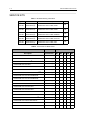
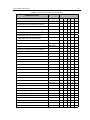
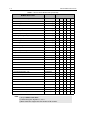
Accessories-to-Model Chart. . . . . . . . . . . . . . . . . . . . . . . . . . . . . . . . . . . . . . . . . 2-4
CHAPTER 3 OVERVIEW
General . . . . . . . . . . . . . . . . . . . . . . . . . . . . . . . . . . . . . . . . . . . . . . . . . . . . . . . . . . . 3-1
Digital Modulation Technique . . . . . . . . . . . . . . . . . . . . . . . . . . . . . . . . . . . . . . . . 3-1
Voice Compression Technology. . . . . . . . . . . . . . . . . . . . . . . . . . . . . . . . . . . . . . . . 3-2

xii CONTENTS
CHAPTER 4 PROGRAMMING THE TERMINAL . . . . . . . . . . . . . . . . . . . . . . . . . . . .4-1
CHAPTER 5 TEST SETUP & TESTING
Section Introduction . . . . . . . . . . . . . . . . . . . . . . . . . . . . . . . . . . . . . . . . . . . . . . . . 5-1
CHAPTER 5.1 TEST SETUP & TESTING
FOR 380–430 MHZ AND 410–470 MHZ
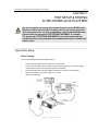
Typical Test Setup . . . . . . . . . . . . . . . . . . . . . . . . . . . . . . . . . . . . . . . . . . . . . . . . . 5.1-1
Before Testing . . . . . . . . . . . . . . . . . . . . . . . . . . . . . . . . . . . . . . . . . . . . . . . . . . . .5.1-1
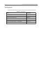
Test Equipment . . . . . . . . . . . . . . . . . . . . . . . . . . . . . . . . . . . . . . . . . . . . . . . . . . . 5.1-2
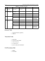
Test Check List . . . . . . . . . . . . . . . . . . . . . . . . . . . . . . . . . . . . . . . . . . . . . . . . . . . 5.1-3
Receiver Tests . . . . . . . . . . . . . . . . . . . . . . . . . . . . . . . . . . . . . . . . . . . . . . . . . . . .5.1-4
Transmitter Tests . . . . . . . . . . . . . . . . . . . . . . . . . . . . . . . . . . . . . . . . . . . . . . . . . .5.1-4
Call Processing Tests. . . . . . . . . . . . . . . . . . . . . . . . . . . . . . . . . . . . . . . . . . . . . . .5.1-4
Duplex Test . . . . . . . . . . . . . . . . . . . . . . . . . . . . . . . . . . . . . . . . . . . . . . . . . . . . . .5.1-5
Configuration of the IFR 2968 System Setup . . . . . . . . . . . . . . . . . . . . . . . . . . . 5.1-5
Configuration of the IFR 2968 Manual Test Screen . . . . . . . . . . . . . . . . . . . . . . 5.1-8
RF Tests . . . . . . . . . . . . . . . . . . . . . . . . . . . . . . . . . . . . . . . . . . . . . . . . . . . . . . . . . 5.1-9
Receiver Tests . . . . . . . . . . . . . . . . . . . . . . . . . . . . . . . . . . . . . . . . . . . . . . . . . . 5.1-9
Simulate Base Station (registration) . . . . . . . . . . . . . . . . . . . . . . . . . . . . . . . . . . . .5.1-9
RSSI Test . . . . . . . . . . . . . . . . . . . . . . . . . . . . . . . . . . . . . . . . . . . . . . . . . . . . . . . .5.1-9
Transmitter Tests . . . . . . . . . . . . . . . . . . . . . . . . . . . . . . . . . . . . . . . . . . . . . . . 5.1-10
Call Processing Test. . . . . . . . . . . . . . . . . . . . . . . . . . . . . . . . . . . . . . . . . . . . . 5.1-11
Talk Back . . . . . . . . . . . . . . . . . . . . . . . . . . . . . . . . . . . . . . . . . . . . . . . . . . . . . . .5.1-11
Call to Mobile . . . . . . . . . . . . . . . . . . . . . . . . . . . . . . . . . . . . . . . . . . . . . . . . . . . .5.1-11
Duplex Test (Phone/Private Mode) . . . . . . . . . . . . . . . . . . . . . . . . . . . . . . . . . . .5.1-11
Digital Duplex Test (Tx) . . . . . . . . . . . . . . . . . . . . . . . . . . . . . . . . . . . . . . . . . . . .5.1-11
Manual Mode Testing . . . . . . . . . . . . . . . . . . . . . . . . . . . . . . . . . . . . . . . . . . . . . 5.1-13
Preparation for Testing. . . . . . . . . . . . . . . . . . . . . . . . . . . . . . . . . . . . . . . . . . . . .5.1-13
Tests. . . . . . . . . . . . . . . . . . . . . . . . . . . . . . . . . . . . . . . . . . . . . . . . . . . . . . . . . . .5.1-13
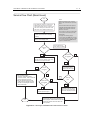
Service Flow Chart (Board Level) . . . . . . . . . . . . . . . . . . . . . . . . . . . . . . . . . . . 5.1-15
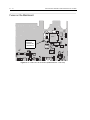
Fuses on the Mainboard . . . . . . . . . . . . . . . . . . . . . . . . . . . . . . . . . . . . . . . . . . . 5.1-16
CHAPTER 6 MAINTENANCE
Introduction . . . . . . . . . . . . . . . . . . . . . . . . . . . . . . . . . . . . . . . . . . . . . . . . . . . . . . . 6-1
Preventive Maintenance . . . . . . . . . . . . . . . . . . . . . . . . . . . . . . . . . . . . . . . . . . . . . 6-1
Inspection . . . . . . . . . . . . . . . . . . . . . . . . . . . . . . . . . . . . . . . . . . . . . . . . . . . . . . . . . 6-1
Cleaning . . . . . . . . . . . . . . . . . . . . . . . . . . . . . . . . . . . . . . . . . . . . . . . . . . . . . . . . . . 6-1
Cleaning External Plastic Surfaces . . . . . . . . . . . . . . . . . . . . . . . . . . . . . . . . . . . . . 6-2
Cleaning Internal Circuit Boards and Components . . . . . . . . . . . . . . . . . . . . . . . . . 6-2
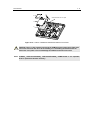
Safe Handling of CMOS and LDMOS Devices . . . . . . . . . . . . . . . . . . . . . . . . . . . 6-3
General Repair Procedures and Techniques . . . . . . . . . . . . . . . . . . . . . . . . . . . . 6-4
Pre-baking of Integrated Circuits. . . . . . . . . . . . . . . . . . . . . . . . . . . . . . . . . . . . . . 6-6
Repair Procedures and Techniques – General . . . . . . . . . . . . . . . . . . . . . . . . . . . 6-7
Parts Replacement and Substitution . . . . . . . . . . . . . . . . . . . . . . . . . . . . . . . . . . 6-7
Disassembling and Reassembling the Terminal – General. . . . . . . . . . . . . . . . . 6-7
Terminal Disassembly and Reassembly – Detailed . . . . . . . . . . . . . . . . . . . . . . . 6-8
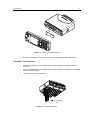
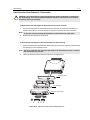
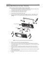
Enhanced Control Head Removal . . . . . . . . . . . . . . . . . . . . . . . . . . . . . . . . . . . . . . 6-8
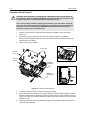
Top Plastic Cover Removal . . . . . . . . . . . . . . . . . . . . . . . . . . . . . . . . . . . . . . . . . . . 6-9
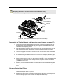
Transceiver Board Removal. . . . . . . . . . . . . . . . . . . . . . . . . . . . . . . . . . . . . . . . . . 6-10
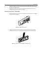
Reassembly the Terminal Chassis And Transceiver Board . . . . . . . . . . . . . . . . . . 6-11
Enhanced Control Head Fitting . . . . . . . . . . . . . . . . . . . . . . . . . . . . . . . . . . . . . . . 6-11
Enhanced Control Head – Disassembly. . . . . . . . . . . . . . . . . . . . . . . . . . . . . . . . . 6-12

CONTENTS xiii
Enhanced Control Head – Reassembly . . . . . . . . . . . . . . . . . . . . . . . . . . . . . . . . . 6-13
Remote Head Enhanced – Disassembly . . . . . . . . . . . . . . . . . . . . . . . . . . . . . . . . 6-14
Remote Head Enhanced – Reassembly . . . . . . . . . . . . . . . . . . . . . . . . . . . . . . . . 6-15
Remote Mount Enhanced Control Head – Disassembly . . . . . . . . . . . . . . . . . . . . 6-15
Remote Mount Enhanced Control Head – Reassembly. . . . . . . . . . . . . . . . . . . . . 6-16
Data Expansion Head Enhanced – Disassembly. . . . . . . . . . . . . . . . . . . . . . . . . . 6-17
Data Expansion Head Enhanced – Reassembly . . . . . . . . . . . . . . . . . . . . . . . . . . 6-18
Motorcycle Mount Enhanced Control Head – Disassembly . . . . . . . . . . . . . . . . . . 6-19
Motorcycle Mount Enhanced Control Head – Reassembly . . . . . . . . . . . . . . . . . . 6-20
Service Aids. . . . . . . . . . . . . . . . . . . . . . . . . . . . . . . . . . . . . . . . . . . . . . . . . . . . . . 6-20
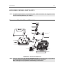
EXPLODED VIEWS & PARTS LISTS . . . . . . . . . . . . . . . . . . . . . . . . . . . . . . . . . . 6-21
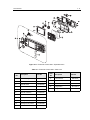
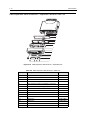
Transceiver – Exploded View and Parts List . . . . . . . . . . . . . . . . . . . . . . . . . . . 6-21
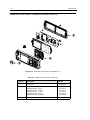
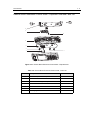
Enhanced Control Head – Exploded View and Parts List . . . . . . . . . . . . . . . . . 6-24
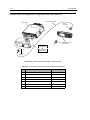
Data Expansion Head Enhanced – Exploded View and Parts List. . . . . . . . . . . 6-26
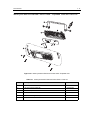
Remote Mount Enhanced Control Head – Exploded View and Parts List . . . . . 6-27
Remote Mount Configuration – Exploded View and Parts List. . . . . . . . . . . . . . 6-28
Motorcycle Mount Enhanced Control Head – Exploded View and Parts List. . . 6-29
APPENDIX A REPLACEMENT PARTS & KITS
Servicing MTM800 with Enhanced Control Head Mobile Units. . . . . . . . . . . . . . A-1
Level 1 and Level 2 Maintenance . . . . . . . . . . . . . . . . . . . . . . . . . . . . . . . . . . . . . . A-1
Level 3 Maintenance . . . . . . . . . . . . . . . . . . . . . . . . . . . . . . . . . . . . . . . . . . . . . . . . A-1
Replacement Parts . . . . . . . . . . . . . . . . . . . . . . . . . . . . . . . . . . . . . . . . . . . . . . . . . A-1
SERVICE INFORMATION. . . . . . . . . . . . . . . . . . . . . . . . . . . . . . . . . . . . . . . . . . . . . A-2
Europe, Middle East and Africa Region . . . . . . . . . . . . . . . . . . . . . . . . . . . . . . . . A-2
European Radio Support Centre (ERSC). . . . . . . . . . . . . . . . . . . . . . . . . . . . . . . . . A-2
EMEA Systems Support Centre (ESSC) . . . . . . . . . . . . . . . . . . . . . . . . . . . . . . . . . A-2
Piece Parts. . . . . . . . . . . . . . . . . . . . . . . . . . . . . . . . . . . . . . . . . . . . . . . . . . . . . . . . A-2
Parts identification and ordering. . . . . . . . . . . . . . . . . . . . . . . . . . . . . . . . . . . . . . . . A-2
EMEA Test Equipment Support . . . . . . . . . . . . . . . . . . . . . . . . . . . . . . . . . . . . . . . . A-2
Asia, Pacific Region . . . . . . . . . . . . . . . . . . . . . . . . . . . . . . . . . . . . . . . . . . . . . . . A-3
Piece Parts. . . . . . . . . . . . . . . . . . . . . . . . . . . . . . . . . . . . . . . . . . . . . . . . . . . . . . . . A-3
Technical Support . . . . . . . . . . . . . . . . . . . . . . . . . . . . . . . . . . . . . . . . . . . . . . . . . . A-3
Further Assistance From Motorola. . . . . . . . . . . . . . . . . . . . . . . . . . . . . . . . . . . . . . A-3
Parts identification and ordering. . . . . . . . . . . . . . . . . . . . . . . . . . . . . . . . . . . . . . . . A-3
Latin America Region. . . . . . . . . . . . . . . . . . . . . . . . . . . . . . . . . . . . . . . . . . . . . . A-4
SERVICE KITS . . . . . . . . . . . . . . . . . . . . . . . . . . . . . . . . . . . . . . . . . . . . . . . . . . . . A-6
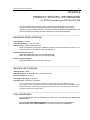
APPENDIX B PRODUCT SPECIFIC INFORMATION
Equipment Electrical Ratings. . . . . . . . . . . . . . . . . . . . . . . . . . . . . . . . . . . . . . . . . B-1
Normal Load Conditions: . . . . . . . . . . . . . . . . . . . . . . . . . . . . . . . . . . . . . . . . . . . . B-1
Fuse Identification. . . . . . . . . . . . . . . . . . . . . . . . . . . . . . . . . . . . . . . . . . . . . . . . . . B-1
SPEZIELLE PRODUKTINFORMATIONEN
Nennwerte für das Funkgerät. . . . . . . . . . . . . . . . . . . . . . . . . . . . . . . . . . . . . . . . . B-2
Betriebsbedingungen . . . . . . . . . . . . . . . . . . . . . . . . . . . . . . . . . . . . . . . . . . . . . . . B-2
Sicherungen. . . . . . . . . . . . . . . . . . . . . . . . . . . . . . . . . . . . . . . . . . . . . . . . . . . . . . . B-2

xiv
Notes

SCOPE & WARRANTY INFORMATION 1 - 1
CHAPTER 1
SCOPE & WARRANTY INFORMATION
SCOPE OF THIS MANUAL
This manual is intended for use by trained service technicians familiar with similar types of
equipment only. It contains information required for the installation of the equipment described and
is current as of the printing date. Changes which occur after the printing date may be incorporated
by a complete Manual revision or alternatively as additions.
This manual is divided into the following sections:
•Copyright
• Document History
• User Safety, Training and General Information
• CHAPTER 1 Scope and Warranty Information
• CHAPTER 2 Model Information & Accessories
• CHAPTER 3 Overview
• CHAPTER 4 Programming the Terminal
• CHAPTER 5.1 Test Setup and Testing for 380 & 410MHz
• CHAPTER 6 Maintenance
• APPENDIX A Replacement Parts and Kits
• APPENDIX B Product Specific Information
NOTE
Before planning or starting the installation, please read the Safety Information
Section in the front of this manual.

1 - 2 SCOPE & WARRANTY INFORMATION
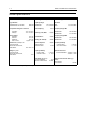
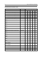
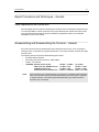
EMEA Manuals & User Guides
Product Information Manual
6866537D87 MTM800/MTM800 with Enhanced Control Head Product Information (and programming)
Manual
Installation Instructions
6866539D30 MTM800 with Enhanced Control Head Installation Manual (English)
Service Manuals
6866539D29 MTM800 with Enhanced Control Head 380-430MHz Detailed Service Manual (English)
6866539D31 MTM800 with Enhanced Control Head 410-470MHz Detailed Service Manual (English)
6866539D28 MTM800 with Enhanced Control Head Basic Service Manual (English)
User Guides
6866539D24 MTM800 with Enhanced Control Head Basic User Guide (EN / DE / FR / ES / NL / AR)
6866539D34 MTM800 with Enhanced Control Head Basic User Guide (EN / RU / IT / PL)
6866539D35 MTM800 with Enhanced Control Head Basic User Guide (EN / SV / PT Braz / NO / DK)
6866539D25 MTM800 with Enhanced Control Head Feature User Guide (English) only available on
MOL: (https://emeaonline.motorola.com)
Safety Leaflets
6866537D37 Mobile Safety Leaflet (EMEA)

SCOPE & WARRANTY INFORMATION 1 - 3
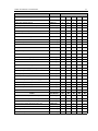
LACR Manuals & User Guides
Product Information Manual
6866537D87 MTM800/MTM800 with Enhanced Control Head Product Information (and programming)
Manual
Installation Instructions
6866539D30 MTM800 with Enhanced Control Head Installation Manual (English)
Service Manuals
6866539D29 MTM800 with Enhanced Control Head 380-430MHz Detailed Service Manual (English)
6866539D31 MTM800 with Enhanced Control Head 410-470MHz Detailed Service Manual (English)
6866539D28 MTM800 with Enhanced Control Head Basic Service Manual (English)
User Guides
6866539D24 MTM800 with Enhanced Control Head Basic User Guide (EN / DE / FR / ES / NL / AR)
6866539D34 MTM800 with Enhanced Control Head Basic User Guide (EN / RU / IT / PL)
6866539D35 MTM800 with Enhanced Control Head Basic User Guide (EN / SV / PT Braz / NO / DK)
6866539D25 MTM800 with Enhanced Control Head Feature User Guide (English) only available on
MOL: (https://emeaonline.motorola.com)
CPS Start Up Manual
6881097C10 MTM800 CPS Start Up Manual (English, Spanish, Portuguese)
CD ROM
9964416H09 MTM800 Documentation CD
(includes 6881097C65, 6881097C66, 6881097C67 and 6881097C68)
Safety Leaflets
6804112J96 Mobile Safety Leaflet (APAC & LACR)
6804113J25 Mobile Safety Leaflet (APAC & LACR) especially for TETRA Mobiles

1 - 4 SCOPE & WARRANTY INFORMATION
Warranty and Service Support
Motorola offers long term support for its products. This support includes full exchange and/or repair
of the product during the warranty period, and service/ repair or spare parts support out of warranty.
Warranty Period and Return Instructions
The terms and conditions of warranty are defined fully in the Motorola Dealer or Distributor or
Reseller contract. These conditions may change from time to time and the following notes are for
guidance purposes only. In instances where the product is covered under a "return for replacement"
or "return for repair" warranty, a check of the product should be performed prior to shipping the unit
back to Motorola. This is to ensure that the product has been correctly programmed or has not been
subjected to damage outside the terms of the warranty.
Prior to shipping any terminal back to the appropriate Motorola warranty depot, please contact
Customer Resources or your Motorola dealer, distributor or reseller. All returns must be
accompanied by a Warranty Claim Form, available from your Customer Service representative or
Motorola Online Extranet (MOL) or your Motorola dealer, distributor or reseller (refer to list in
Appendix A). Products should be shipped back in the original packaging, or correctly packaged to
ensure no damage occurs in transit.
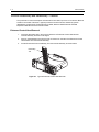
After Warranty Period
After the Warranty period, Motorola continues to support its products in two ways.
• Motorola's Regional Radio Support Centres offer a repair service to both end users
and dealers at competitive prices.
• AAD supplies individual parts and modules that can be purchased by dealers who
are technically capable of performing fault analysis and repair.
Page is loading ...
Page is loading ...
Page is loading ...
Page is loading ...
Page is loading ...
Page is loading ...
Page is loading ...
Page is loading ...
Page is loading ...
Page is loading ...
Page is loading ...
Page is loading ...
Page is loading ...
Page is loading ...
Page is loading ...
Page is loading ...
Page is loading ...
Page is loading ...
Page is loading ...
Page is loading ...
Page is loading ...
Page is loading ...
Page is loading ...
Page is loading ...
Page is loading ...
Page is loading ...
Page is loading ...
Page is loading ...
Page is loading ...
Page is loading ...
Page is loading ...
Page is loading ...
Page is loading ...
Page is loading ...
Page is loading ...
Page is loading ...
Page is loading ...
Page is loading ...
Page is loading ...
Page is loading ...
Page is loading ...
Page is loading ...
Page is loading ...
Page is loading ...
Page is loading ...
Page is loading ...
Page is loading ...
Page is loading ...
Page is loading ...
Page is loading ...
Page is loading ...
Page is loading ...
Page is loading ...
Page is loading ...
Page is loading ...
Page is loading ...
Page is loading ...
Page is loading ...
Page is loading ...
Page is loading ...
Page is loading ...
Page is loading ...
Page is loading ...
Page is loading ...
Page is loading ...
Page is loading ...
Page is loading ...
Page is loading ...
-
 1
1
-
 2
2
-
 3
3
-
 4
4
-
 5
5
-
 6
6
-
 7
7
-
 8
8
-
 9
9
-
 10
10
-
 11
11
-
 12
12
-
 13
13
-
 14
14
-
 15
15
-
 16
16
-
 17
17
-
 18
18
-
 19
19
-
 20
20
-
 21
21
-
 22
22
-
 23
23
-
 24
24
-
 25
25
-
 26
26
-
 27
27
-
 28
28
-
 29
29
-
 30
30
-
 31
31
-
 32
32
-
 33
33
-
 34
34
-
 35
35
-
 36
36
-
 37
37
-
 38
38
-
 39
39
-
 40
40
-
 41
41
-
 42
42
-
 43
43
-
 44
44
-
 45
45
-
 46
46
-
 47
47
-
 48
48
-
 49
49
-
 50
50
-
 51
51
-
 52
52
-
 53
53
-
 54
54
-
 55
55
-
 56
56
-
 57
57
-
 58
58
-
 59
59
-
 60
60
-
 61
61
-
 62
62
-
 63
63
-
 64
64
-
 65
65
-
 66
66
-
 67
67
-
 68
68
-
 69
69
-
 70
70
-
 71
71
-
 72
72
-
 73
73
-
 74
74
-
 75
75
-
 76
76
-
 77
77
-
 78
78
-
 79
79
-
 80
80
-
 81
81
-
 82
82
-
 83
83
-
 84
84
-
 85
85
-
 86
86
-
 87
87
-
 88
88


Motorola TETRA MTM800 Basic Service Manual
- Type
- Basic Service Manual
Ask a question and I''ll find the answer in the document
Finding information in a document is now easier with AI
Related papers
-
Motorola TETRA MTM800 User manual
-
-
-
-
-
-
-
-
-
Other documents
-
Belson BS-13011 User manual
-
Avaya 1100 Series (SIP Firmware) User guide
-
Panasonic TK-CJ300-WTH Owner's manual
-
Tetra Tetra ColorFusion Starter aquarium Kit 3 Gallons, Half-Moon Shape, click here
-
Panasonic EY37A1 User manual
-
GE LED Accent Lighting Installation guide
-
Martin M1 Installation guide
-
Packard Bell 300 User manual
-
Rapid M2000 User Manual & Installation Manual
-