Page is loading ...

48'' Galvanized Cone Fan (Belt Drive)
Installation & Operator’s Instruction Manual
MV1077BFebruary 1999

MV1399B

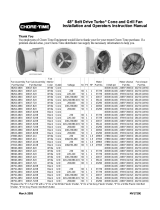
48" Galvanized Cone Fan Chore-Time Warranty
MV1077B 3
Chore-Time Equipment warrants each new product manufactured by it to be free from defects in material or
workmanship for one year from the date of initial installation by the original purchaser. If such a defect is found
by Chore-Time to exist within the one year period, Chore-Time will, at its option, (a) repair or replace such
product free of charge, F.O.B. the factory of manufacture, or (b) refund to the original purchaser the original
purchase price, in lieu of such repair or replacement.
Conditions and limitations:
1. The product must be installed and operated in accordance with instructions published by Chore-Time or
warranty will be void.
2. Warranty is void if all components of a system are not supplied by Chore-Time.
3. This product must be purchased from and installed by an authorized Chore-Time dealer or certified
representative thereof, or the warranty will be void.
4. Malfunctions or failure resulting from misuse, abuse, negligence, alteration, accident, or lack of proper
maintenance shall not be considered defects under this warranty.
5. This warranty applies only to systems for the care of poultry and livestock. Other applications in industry
or commerce are not covered by this warranty.
Chore-Time shall not be liable for any Consequential or Special Damage which any purchaser may suffer or
claim to have suffered as a result of any defect in the product. “Consequential” or “Special Damages” as used
herein include, but are not limited to, lost or damaged products or goods, costs of transportation, lost sales, lost
orders, lost income, increased overhead, labor and incidental costs and operational inefficiencies.
THIS WARRANTY CONSTITUTES CHORE-TIME’S ENTIRE AND SOLE WARRANTY AND CHORE-
TIME EXPRESSLY DISCLAIMS ANY AND ALL OTHER WARRANTIES, INCLUDING, BUT NOT
LIMITED TO, EXPRESS AND IMPLIED WARRANTIES AS TO MERCHANTABILITY, FITNESS FOR
PARTICULAR PURPOSE SOLD AND DESCRIPTION OR QUALITY OF THE PRODUCT FURNISHED
HEREUNDER.
Any exceptions to this warranty must be authorized in writing by an officer of the company. Chore-Time reserves
the right to change models and specifications at any time without notice or obligation to improve previous models.
CHORE-TIME EQUIPMENT, A Division of CTB, Inc.
P.O. Box 2000
Milford, Indiana 46542-2000 U.S.A.
Chore-Time Warranty

Contents
Topic Page User*
4 MV1077B
* Legend: C = Customer (end user), D = Distributor (sales), I = Installer of equipment
Chore-Time Warranty . . . . . . . . . . . . . . . . . . . . . . . . . . . . . . . . . . . . . . . . . . . . . . . . 3 C, D
General. . . . . . . . . . . . . . . . . . . . . . . . . . . . . . . . . . . . . . . . . . . . . . . . . . . . . . . . . . . . . 5 C, D, I
Support Information . . . . . . . . . . . . . . . . . . . . . . . . . . . . . . . . . . . . . . . . . . . . . . . . . . . . . . .5
Distributor and Installer Information . . . . . . . . . . . . . . . . . . . . . . . . . . . . . . . . . . . . . . . . . .5
About This Manual. . . . . . . . . . . . . . . . . . . . . . . . . . . . . . . . . . . . . . . . . . . . . . . . . . . 6 C, D, I
Safety Information . . . . . . . . . . . . . . . . . . . . . . . . . . . . . . . . . . . . . . . . . . . . . . . . . . . 7 C, I
Safety–Alert Symbol. . . . . . . . . . . . . . . . . . . . . . . . . . . . . . . . . . . . . . . . . . . . . . . . . . . . . . .7
Understanding Signal Words . . . . . . . . . . . . . . . . . . . . . . . . . . . . . . . . . . . . . . . . . . . . . . . .7
Follow Safety Instructions . . . . . . . . . . . . . . . . . . . . . . . . . . . . . . . . . . . . . . . . . . . . . . . . . .8
Decal Descriptions . . . . . . . . . . . . . . . . . . . . . . . . . . . . . . . . . . . . . . . . . . . . . . . . . . . . . . . .8
Fan Installation . . . . . . . . . . . . . . . . . . . . . . . . . . . . . . . . . . . . . . . . . . . . . . . . . . . . . . 9 I
Shutter Installation. . . . . . . . . . . . . . . . . . . . . . . . . . . . . . . . . . . . . . . . . . . . . . . . . . .15 I
Product Specifications and Part Numbers . . . . . . . . . . . . . . . . . . . . . . . . . . . . . . . . 17 C, I
Motor Specifications and Part Numbers. . . . . . . . . . . . . . . . . . . . . . . . . . . . . . . . . . . . . . . 17
Plastic Shutter Part Numbers . . . . . . . . . . . . . . . . . . . . . . . . . . . . . . . . . . . . . . . . . . . . . . . 17
48'' Galvanized Cone Fan Part Numbers . . . . . . . . . . . . . . . . . . . . . . . . . . . . . . . . . . . . . . 18

48" Galvanized Cone Fan General
MV1077B 5
Support Information
The Chore-Time 48" Galvanized Cone Fans are designed to be used as exhaust fans. The Fans are shipped
assembled. Using this equipment for any other purpose or in a way not within the operating recommendations
specified in this manual will void the warranty and may cause personal injury.
This manual is designed to provide comprehensive planning, installation, operation, and parts listing information.
The Table of Contents provides a convenient overview of the information in this manual. The Table of Contents
also specifies which pages contain information for the sales personnel, installer, and consumer (end user).
IMPORTANT: CE stands for Certified Europe. It is a standard which
equipment must meet or exceed in ordered to be sold in Europe. CE provides
a benchmark for safety and manufacturing issues. CE is required only on
equipment sold in Europe.
Chore-Time Equipment recognizes CE Mark and pursues compliance in all
applicable products. Fill in the CE-Mark serial number in the blank space
provided for future reference.
Distributor and Installer Information
General
(CE-mark serial number)
Please fill in the following information about your Product.
Keep this manual in a clean, dry place for future reference.
Distributor’s Name___________________________________________________
Distributor’s Address ________________________________________________
Distributor’s Phone _______________________ Date of Purchase ___________
Installer’s Name _____________________________________________________
Installer’s Address___________________________________________________
Installer’s Phone _______________________ Date of Installation ___________
System Specifications________________________________________________
___________________________________________________________________

About This Manual 48" Galvanized Cone Fan
6 MV1077B
The intent of this manual is to help you in two ways. One, to provide step-by-step
instructions on the assembly of your product. Two, to provide an easy reference if
you have questions in a particular area.
Important ! Read ALL instructions carefully before starting construction.
Important ! Pay particular attention to all SAFETY information.
• Metric measurements are shown in millimeters and in brackets, unless otherwise
specified. “ " ” equals inches and “ ' ” equals feet in English measurements.
Examples:
1'' [25.4]
4' [1 219]
• Optional equipment contains necessary instructions for assembly or operation.
• Major changes from the last printing will be listed on the back cover.
• This Planning Symbol is used in areas where planning needs to take place before
construction continues.
• Very small numbers near an illustration (i.e., 1257-48) are identification of the
graphic, not a part number.
About This Manual

48" Galvanized Cone Fan Safety Information
MV1077B 7
Caution, Warning and Danger Decals have been placed on the equipment to warn
of potentially dangerous situations. Care should be taken to keep this information in
good condition, intact, and easy to read at all times. Replace missing or damaged
decals.
Using the equipment for purposes other than specified in this manual may cause
personal injury and or damage to the equipment.
Safety–Alert Symbol
This is a safety–alert symbol. When you see this symbol on your equipment, be alert
to the potential for personal injury. This equipment is designed to be installed and
operated as safely as possible...however, hazards do exist.
Understanding Signal Words
Signal words are used in conjunction with the safety–alert symbol to identify the
severity of the warning.
DANGER indicates an imminently hazardous situation which, if not avoided, WILL
result in death or serious injury.
WARNING indicates a potentially hazardous situation which, if not avoided, COULD
result in death or serious injury.
CAUTION indicates a hazardous situation which, if not avoided, MAY result in
minor or moderate injury.
Safety Information

Safety Information 48" Galvanized Cone Fan
8 MV1077B
Safety Information - continued
Follow Safety Instructions
Carefully read all safety messages in this manual and on your equipment decals.
Follow recommended precautions and safe operating practices.
Decal Descriptions
This diagram shows the proper location of the safety decal “DANGER—
ROTATING FAN BLADE” as shipped from the factory. Replace damaged or
missing decals. Make sure the decals may be seen at all times.
NOTE These decals are on placed on both sides of shroud.
IMPORTANT Chore-Time Equipment strongly recommends that a good alarm system
should be installed in confinement buildings to warn of power failure
and high temperature.
Chore-Time Equipment also recommends that an alternate power
source be available for confinement buildings in case of power failure.
1077-01 2/99
1399-10 11/98

48" Galvanized Cone Fan Fan Installation
MV1077B 9
IMPORTANT The 48'' Cone Fan must be installed in a side wall.
Build fan framing out of 2'' (50 mm) lumber (not supplied). The required rough
opening is provided in the table below. Allow a minimum 4'' spacing between framed
openings for adjacent fans. This will provide clearance for the mounting flange.
Fan Installation
F
MV1399-01 3/98
F
Figure 1. Framing Diagram (front view)
Figure 2. Fan (side view)
A
Square
B C D E F
Rough Opening
Square
48" Fan 58-1/4"x58-1/4" 50-3/8" 45-3/16" 2" 5-1/2" 55"x55"
B
A
D
C
E
1574-01 11/98

Fan Installation 48" Galvanized Cone Fan
10 MV1077B
Fan Installation - continued
Insert the Fan Assembly in the framed opening in the side wall
Center the Fan Assembly in the framed opening, left to right. Allow the Fan Housing
to set on the bottom of the framed opening.
Secure the Fan Assembly to the framed opening, using (1) 1/4'' x 1-3/4'' Lag Screw
through the middle hole on each side and (3) 1/4''x1-3/4'' Lag Screws across the
bottom panel. See Figure 3. Lag Screws are supplied in the Hardware Package.
Install the Shutters Clips in the remaining holes on the sides and top of the Fan. The
Shutter Clips need to be tight, but loose enough to be turned. See Figure 4
Figure 3. Fan Assembly (side view)
Item Description
1 Fan Assembly
2 Side Wall of Building
3 1/4''x1-3/4'' Lag Screw (5 used)
2
1
3
1077-2 2/99
Figure 4. Shutter Clip Installation (front view)
Item Description
1 Fan Assembly
2 1/4''x1-3/4'' Lag Screw
3 Shutter Clip
4 Nylon Flat Washer
1077-03 2/99
1
2
3
4

48" Galvanized Cone Fan Fan Installation
MV1077B 11
The Cone must be assembled and installed in the field.
Important: The Fan must be installed in the wall before installing the Cone to the
Fan.
Lay the Cone Panels, with the flanges up, on a flat surface, as shown in Figure 4.
Loosely, fasten the Side Panels together with (3) 5/16-18 x 5/8'' carriage bolts, (3) 3/
8'' lock washers, and (3) 5/16-18 hex nuts per joint. Only install hardware at the
locations shown in Figure 4.
Do not tighten the hardware.
Cone Assembly and Installation
Item Description
1 Cone Panel
2 5/16-18 Hex Nut
3 3/8'' Lock Washer
4 5/16-18 x 5/8” Carriage Bolts
5 Do not install hardware here.
Figure 4. Cone Assembly (top view)
1
2
3
4
5
1077-04 2/99

Fan Installation 48" Galvanized Cone Fan
12 MV1077B
Set the Cone Side Panels up and align the ends to create the cone shaped housing.
Loosely, secure the ends similar to the other joints.
Note: The flanges should be on the outside of the Cone.
Position the Grill in the larger end of the Cone Assembly. Secure the Grill in place
using the 5/16-18 carriage bolts, 3/8” lock washers, and 5/16-18 hex nuts. See Figure
5. This will help maintain the shape of the Cone Assembly while it is being secured
to the Fan Shroud.
Secure each Cone Hanger Bracket to the Fan Shroud, using 5/16-18 carriage bolts,
3/8'' lock washers, and 5/16-18 hex nuts. See Figure 6.
Item Description
1 Cone Assembly
2 Grill
3 5/16-18 Carriage Bolt
4 3/8” Lock Washer
5 5/16-18 Hex Nut
DANGER:
The Grill MUST be
installed to prevent
serious injury or
death.
Figure 5. Grill Installation (front view)
1077-05 2/99
1
2
3
4
5
1077-06 2/99
1
2
4
3
5
Key Description
1 Fan Assembly
2 5/16-18 x 5/8” Carriage Bolt
3 Cone Hanger Bracket
4 5/16-18 Hex Nut
5 3/8” Lock Washer
Figure 6. Hanger Bracket Installation (side view)

48" Galvanized Cone Fan Fan Installation
MV1077B 13
With the help of an assistant, lift the Cone Assembly to the Fan Shroud. Slide the
smaller end of the Cone Assembly over the Fan Shroud. Rotate the Cone Assembly
to align the Panel Joints with the Cone Hanger Brackets.
Secure the Cone Assembly to the Cone Hanger Brackets using (1) 5/16-18 carriage
bolt, 3/8” lock washer, and 5/16-18 hex nut. See Figure 7.
Tighten all thehardware.
Item Description
1 Fan Assembly
2 Cone Hanger Bracket
3 5/16-18 Hex Nut
4 3/8” Lock Washer
5 Cone Assembly
6 5/16-18 x 5/8” Carriage Bolt
Figure 7. Cone Installation (side view)
1
2
3
4
5
6
1077-07 2/99

Fan Installation 48" Galvanized Cone Fan
14 MV1077B
See wiring diagram on motor for Motor electrical connections. Follow local, state,
and national electrical for wiring.
Install an electrical disconnect within reach of each Fan.
Route the motor cord (not supplied) toward the upper left corner of fan and attach to
the top panel using the 3/8'' cord clip mounted to the 1/4'' hole in the top panel.
See Figure 5.
IMPORTANT If an aluminum Shutter will be installed, route the motor cord through
the Rubber Grommet.
Some installations may require an exit hole for the motor cord be drilled in the side
of the Housing. These installations must have electrical wires routed through conduit
to protect them from damage.
IMPORTANT Make sure the conduit or wires do not interfere with the Fan Blades or
Shutter operation.
Wiring Instuctions
Figure 5. Installation of Cord Clip
Item Description
1 Slant Wall Top Panel
2 Cord Clip
3 Cord (not supplied)
1399-06 11/98
1
3
2

48" Galvanized Cone Fan Shutter Installation
MV1077B 15
Plastic and Aluminum Shutters are available, however installation is different.
See below.
1. If you have a Plastic Shutter—cut a 3/8" slot in the upper left or right flange of
the Shutter frame in order to route the electrical cord out the back.
2. If you have an Aluminum Shutter, route the electrical cord through the notch in
the top of the Shutter Frame. Make sure the Grommet is installed correctly in the
notch in the Shutter Frame. See Figure 6.
3. The Slant Wall Bottom Panel is designed to hold the Shutter. Slide the bottom of
the Shutter into position in the Bottom Panel of the Slant Wall Kit, lean the
Shutter back and lock it in place rotating the Shutter Clips. Check the Shutter for
proper operation—the shutter must be able to open and close freely without
obstructions. See Figure 6.
NOTE Make sure the electrical conduit and wire does not interfere with the Fan
Blades or Shutter operation.
Shutter Installation
Figure 6. Shutter Installation (front view)
Item Description
1 Grommet (for aluminum shutter)
2 Shutter
3 Shutter Clip
4 Slant Wall Housing
5 3/8'' Slot in Plastic Shutter
1077-08 2/99
4
3
2
5
1

Shutter Installation 48" Galvanized Cone Fan
16 MV1077B
DANGER Disconnect Power Prior To Maintaining Or Cleaning The Fan. The fan
may start automatically causing serious injury or death.
• Service and maintenance of fans should be done only by a qualified technician.
• Keep the fan clean for maximum life and best performance. Do not spray
water on Fan Shaft Bearings.
• Periodically check the V-Belt. If necessary, adjust the spring tension to prevent
the belt from slipping. The spring should be stretched to an overall length of 6''
to 7'' for proper belt tension.
• Two options are available for V-Belt replacement.
1. Red Link V-Belt (see parts listing), which does not require disassembly of
the fan.
2. Black V-Belt (see parts listing), which requires the removal of the Fan Blade
or Fan Shaft.
• The Motor and Fan Shaft Bearings are permanently lubricated. Grease Zerks are
provided on the Fan Shaft Bearings for installations where relubrication is
needed. Relubrication is required whenever water comes in contact with the Fan
Shaft Bearings. Slowly rotate the Fan Shaft as bearing is filled with Grease. Use
only high quality lithium soap base grease and clean all dirt from Zerk before
applying grease.
Maintenance

48" Galvanized Cone Fan Product Specifications and Part Numbers
MV1077B 17
Motor Specifications and Part Numbers
Plastic Shutter Part Numbers
Product Specifications and Part Numbers
Fan Specifications
(assembled)
Motor Specifications
Description
*Part No.
Voltage HZ Phase HP Motor
P/N
Motor
Sheave
P/N
Fan
Sheave
P/N
48''Cone
Fan BD
42049-482X 115/230 60 1 1 37729 35333 35009
42049-483X 230 50 1 1 37729 8773 35009
42049-484X 208-230/460 60 3 1 40157 35333 35009
42049-485X 220-240/380-415 50 3 1 36142 24697 35009
42049-486X 230/380-415 60 3 1 36142 35333 35009
* Replace the "X" in fan P/N with "1" for an aluminum Shutter, "2" for a plastic shutter.
Item Description Part no.
1 Shutter Plastic (complete) 38029
2 Push Nut 1/4'' 38032
3 Shutter Rod Pivot 38702-4
4 Shutter Louver 38038-4
1
3
3
2
4

Product Specifications and Part Numbers 48" Galvanized Cone Fan
18 MV1077B
48'' Galvanized Cone Fan Part Numbers
1077-09 2/99
18
23
2313
22
17
1
20
7
8
19
9
6
4
25 11
14
5
12
10
27
28
40
41
42
43
44
34
Item Description Part No
*1 Motor See Chart
4 Top Panel 5° 42052
5 Bottom Panel 5° 42050
6 Shroud (54) 37583
7 Danger Decal 2527-50
8 Fan Blade 28140
9 Side Panel RH 42051-2
10 Side Panel LH 42051-1
11 Post 48'' 38390
12 Bushing 38896
13 Sheave, 8-1/4'' O.D. 1'' Bore 35009
14 Motor Mount 38895
17 V-Belt Black (AX35)
V-Belt Red Link (3.0' required)
4468
30374
*18 Motor Sheave See Chart
19 Support BD Module Bracket 38894
20 Shaft 1'' 34723
22 Bearing, Cast Flange 1'' Bore 38382
23 Square Key 1/4x1x1/8'' 2419-2
25 Spring 7551
27 Bracket, BD Module 38893
40 Cord Clip 7242
41 Grommet 7256
42 1/4x1-3/4'' Lag Screw 39217
43 Shutter Clip 36729
44 Nylon Washer 4856
*See Motor Specifications on previous page.

48" Galvanized Cone Fan Product Specifications and Part Numbers
MV1077B 19
This Page
Currently
Not in Use

Product Specifications and Part Numbers 48" Galvanized Cone Fan
20 MV1077B
Made to work.
Built to last.
Revisions to this Manual
Page No. Description of Change
Complete update of entire manual.
Contact your nearby Chore-Time distributor or representative for additional parts and information.
CTB Inc.
P.O. Box 2000 • Milford, Indiana 46542-2000 • U.S.A.
Phone (219) 658-4101 • Fax (800) 333-4191
E-Mail: [email protected] • Internet: http//www.ctbinc.com
Printed in the U.S.A.
/