Page is loading ...

MV1270A16January 1996
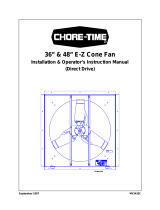
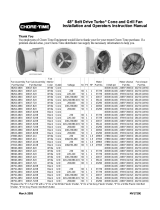
TURBO™
Cone Fans & Grill Fans
Installation & Operator’s Manual
(48” Belt Drive)

48” Belt Drive TURBO™ Fan Installation Manual
•
Page 2
WARRANTY INFORMATION
Chore-Time Equipment warrants each new product manufactured by it to be free from defects in material or
workmanship for one year from the date of initial installation by the original purchaser. If such a defect is found
by Chore-Time to exist within the one year period, Chore-Time will, at its option, (a)repair or replace such
product free of charge, F.O.B. the factory of manufacture, or (b) refund to the original purchaser the original
purchase price, in lieu of such repair or replacement.
Additional extended warranties are herewith provided to the original purchaser as follows:
1. TURBO™ and RLX™ Fans, less motors, for three years from date of installation.
*2. Poultry feeder pans that become unusable within five years from date of installation.
Warranty prorated after three years usage.
3. MEAL-TIME Hog Feeder pans that become unusable within five years of installation.
4. Rotating centerless augers, excluding applications involving High Moisture Corn
(exceeding 18%), for ten years from date of installation. Note: MULTIFLO and
applications involving High Moisture Corn are subject to a one year warranty.
5. Chore-Time manufactured roll-formed steel auger tubes for ten years from date of
installation.
*6. Laying cages that become unusable within ten years. Warranty prorated after three years
usage.
*7. ULTRAFLO Auger and ULTRAFLO Feed Trough (except ULTRAFLO Trough
Liners) are warranted for a period of five (5) years from date of original purchase against
repeated breakage of the auger or wear-through of the feed trough caused solely by the
auger.
Conditions and limitations:
1. The product must be installed and operated in accordance with instructions published by
Chore-Time or warranty will be void.
2. Warranty is void if all components of a system are not supplied by Chore-Time.
3. This product must be purchased from and installed by an authorized Chore-Time dealer or
certified representative thereof, or the warranty will be void.
4. Malfunctions or failure resulting from misuse, abuse, negligence, alteration, accident, or
lack of proper maintenance shall not be considered defects under this warranty.
5. This warranty applies only to systems for the care of poultry and livestock. Other
applications in industry or commerce are not covered by this warranty.
Chore-Time shall not be liable for any consequential or special damage which any purchaser may suffer or claim
to have suffered as a result of any defect in the product. "Consequential" or "special damages" as used herein
include, but are not limited to, lost or damaged products or goods, costs of transportation, lost sales, lost orders,
lost income, increased overhead, labor and incidental costs and operational inefficiencies.
THIS WARRANTY CONSTITUTES CHORE-TIME’S ENTIRE AND SOLE WARRANTY AND CHORE-TIME
EXPRESSLY DISCLAIMS ANY AND ALL OTHER WARRANTIES, INCLUDING, BUT NOT LIMITED TO,
EXPRESS AND IMPLIED WARRANTIES AS TO MERCHANTABILITY, FITNESS FOR PARTICULAR
PURPOSE SOLD AND DESCRIPTION OR QUALITY OF THE PRODUCT FURNISHED HEREUNDER.
Any exceptions to this warranty must be authorized in writing by an officer of the company. Chore-Time reserves
the right to change models and specifications at any time without notice or obligation to improve previous models.
*See separate Chore-Time Cage Wire Warranty as to these products.
CHORE-TIME EQUIPMENT, A Division of CTB, Inc.
P.O. Box 2000, Milford, Indiana 46542-2000 U.S.A.

48” Belt Drive TURBO™ Fan Installation Manual
•
Page 3
(CE-mark serial number)
Support Information
The Chore-Time TURBO™ Fans are designed to be used as exhaust fans in highly corrosive environments. The pri-
mary components are made from plastic or stainless steel materials. Using this equipment for any other purpose or
in a way not within the operating recommendations specified in this manual will void the warranty and may cause
personal injury and/or death.
This manual is designed to provide comprehensive planning, installation, wiring, operation, and parts listing infor-
mation. The Table of Contents provides a convenient overview of the informa-
tion in this manual. The Table of Contents also specifies which pages contain
information for the sales personal, installer, and consumer (end user).
IMPORTANT: CE stands for certified Europe. It is a standard which equipment
must meet or exceed in order to be sold in Europe. CE provides a benchmark
for safety and manufacturing issues. CE is required only on equipment sold in
Europe.
Chore-Time Equipment recognizes CE Mark and pursues compliance in all ap-
plicable products. Please fill in the CE-Mark serial number in the blank space
provided for future reference.
Please include the name and address of your Chore-Time Distributor and in-
staller.
Please fill in the following information about your Chore-Time TURBO Fans. Keep this manual in
a clean, dry place for future reference.
Distributor’s Name
Distributor’s Address
Distributor’s Phone Date of Purchase
Installer’s Name
Installer’s Address
Installer’s Phone Date of Installation
System Specifications
Table of Contents
Topic Page User*
Warranty Information..................................................................................................................2 C, D
Support Information ....................................................................................................................3 C, D
Safety Information.......................................................................................................................4 C, I
Technical Information, Tools need to install your Fans..............................................................5 C, I
Planning the Fan Installation.......................................................................................................6 C, I
Fan Installation............................................................................................................................7 - 13 I
48” Belt Drive Fan Parts List......................................................................................................14 C, I
*Legend: C = Customer (end user), D = Distributor (sales), I = Installer of equipment

48” Belt Drive TURBO™ Fan Installation Manual
•
Page 4
Rotating Parts!
Do not operate with
covers removed!
2527-10
Disconnect electrical power
before working on system,
equipment may start auto-
matically. Otherwise severe
personal injury will result.
DANGER
Safety Information
Caution, Warning and Danger Decals have been placed on the equipment to warn of potentially dangerous
situations. Care should be taken to keep this information intact and easy to read at all times. Replace missing
or damaged safety signs.
Chore-Time equipment is designed to be installed and operated as safely as possible...however, hazards do
exist. Using the equipment for purposes other than specified in this manual may cause personal injury or damage
to the equipment.
DANGER
WARNING
CAUTION
SIGNAL WORDS
Signal words are used in conjunction with the safety–alert symbol to
identify the severity of the warning.
DANGER..........indicates an imminently hazardous
situation which, if not avoided, WILL result
in death or serious injury.
WARNING .......indicates a potentially hazardous situation
which, if not avoided, COULD result in
death or serious injury.
CAUTION ........indicates a hazardous situation which, if not
avoided, MAY result in minor or moderate
injury.
This diagram shows the proper location of the safety decals as shipped from the factory. Replace damaged or
missing decals. Make sure the decals may be easily seen at all times.

48” Belt Drive TURBO™ Fan Installation Manual
•
Page 5
Tools needed to install your Fans include:
1. Regular Screwdriver
2. Allen Wrenches
3. Box-End Wrenches
4. Rubber Mallet
5. Wire Cutters
6. Wire Strippers
7. Adequate Size and Quantity of Electrical Wire
8. Electrical Drill and Drill Bits
8 Large pliers or channel locking pliers
9. Another person to help!!
Technical Information
Motor Specifications:
Horsepower- - - - - - - - - - - - - - - - - - - - - - - 1 H.P.
Voltage - - - - - - - - - - - - - - - - - - - - - - - -208-230/460 V
Hz. - - - - - - - - - - - - - - - - - - - - - - - - - - 60 Hz. or 50 Hz.
Phase - - - - - - - - - - - - - - - - - - - - - - - - -Single Phase or Three Phase
R.P.M. - - - - - - - - - - - - - - - - - - - - - - - - - 1725
Blade:
Size - - - - - - - - - - - - - - - - - - - - - - - - - -48” (121.9 cm)
Type - - - - - - - - - - - - - - - - - - - - - - - - - -Stainless Steel
Important
Chore-Time Equipment strongly recommends that a good alarm system should be installed in confinement
buildings to warn of power failure and high temperature.
Chore-Time Equipment also recommends that an alternate power source be available for confinement
buildings in case of power failure.

48” Belt Drive TURBO™ Fan Installation Manual
•
Page 6
Planning the Fan Installation:
Carefully plan the installation. Dimensions are provided for the 48” Fan with
Cones (Figure 1) and without Cones (Figure 2). Be sure to allow enough space
to install fans without interfering with other fans or equipment.
Dimension A B C D E F
57”
(144.8 cm)
54”
(137.2 cm)
12”
(30.5 cm)
16”
(40.6 cm)
57”
(144.8 cm)
54”
(137.2)
Figure 1. Planning and Layout Diagram w/ Cones (front view).
Dimension A B C D E
57”
(144.8 cm)
54”
(137.2 cm)
0”
Minimum
54”
(137.2)
57”
(144.8 cm)
Figure 2. Planning and Layout Diagram w/o Cones (front view).

48” Belt Drive TURBO™ Fan Installation Manual
•
Page 7
Fan Installation
Build wall framing as specified in Figure 3. The required wall opening for each
fan is included in the chart below.
Refer to the planning section for minimum dimension between fans.
The Hardware Kit, supplied, includes (12) #8 screws to secure the fan to the
framed opening. See Figure 4.
Do not allow the top or sides of the shroud to sag when securing to the wall.
The Shroud Flange should be secured square in the opening.
Figure 4. Fan installation (front view).
Dimension 48” Fan
A 54” (137.2 cm)
Minimum
Figure 3. Wall opening requirements (side view).

48” Belt Drive TURBO™ Fan Installation Manual
•
Page 8
Figure 6. Fan Motor installation (side view)
Note: The 48” Belt Drive Fan may be ordered with or without the Motor. The
following instructions provide complete installation information for fans
ordered without the Motor. If your fans include the Motors, install the Fan
Module and Motor Assembly as specified in Figure 5. Skip ahead to Figure 8
for Blade Assembly installation.
Secure the Module Assembly between the Motor Support Post, as shown in
Figure 5. Hardware is included in the Hardware Package.
Figure 5. Fan Module installation (top view).
Key Description
1 5/16-18 Carriage Bolt
2 5/16-18 Hex Nut
3 Motor Support Post
4 Module Assembly
Key Description
1 5/16-18 Carriage Bolt
2 5/16-18 Hex Nut
3 Motor
4 Module Assembly
Set the Motor on the Module Assembly and secure in place, as shown in
Figure6. Hardware is included in the Hardware Package.

48” Belt Drive TURBO™ Fan Installation Manual
•
Page 9
Install the Motor Sheave on the output shaft of the Motor, as shown in
Figure7. Make sure the Motor Sheave is aligned with the Fan Sheave...the
belt must track straight.
Insert the key in the keyway of the output shaft. Tighten 5/16” set screw in the
Motor Sheave to secure the Motor Sheave in place.
Figure 7. Motor Sheave installation (side view).
Key Description
1 Motor Sheave
2 1/4” Sq. Key
3 5/16” Set Screw
4 Fan Sheave
Position the Fan Belt around the Motor Sheave. Make sure the arrows on the
Fan Belt point in the direction of rotation (which is counterclockwise facing
incoming end of fan).
Route the Fan Belt as far around the Fan Sheave as far as possible. Carefully
turn the Fan Sheave to completely install the Fan Belt.
Slide the Fan Blade Assembly onto the Fan Sheave Shaft. The hub of the Fan
Blade Assembly should be approximately flush with the end of the Fan Sheave
Shaft. See Figure 8.
Figure 8. Fan Blade Assembly installation (top view).
Key Description
1 Fan Belt
2 Fan Blade

48” Belt Drive TURBO™ Fan Installation Manual
•
Page 10
Figure 9. Retainer Ring Installation (side view).
Position the Retainer Ring seam near the top of the Shroud, against the Motor
Mount Ring. See Figure 9.
Slide the remainder of the Retainer Ring into the vertical position, against the
Motor Mount Ring.
Cones may be installed to improve the performance of the Fans. If Cones are
not to be installed, proceed to the section describing how to position the
Retainer Ring in the Retainer Ring groove on page 11 (Figure 10 & 11).
Begin by positioning the flange of the Cone in the groove of the Shroud near
the top and around both sides. It is helpful if there is someone on each side to
support the Cone in the groove.
Note: Position the Cone so that one of the slits is straight down.
Use a screwdriver or long tool to pry the remaining portion of the Cone onto the
Shroud. A rubber mallet may be used to help drive the Cone onto the Shroud.
If necessary, the Cone may be secured to the Shroud using stainless steel,
self-drilling screws (not supplied). See Figure 10.
Key Description
1 Shroud
2 Retainer Ring

48” Belt Drive TURBO™ Fan Installation Manual
•
Page 11
Figure 10. Cone Installation (side view).
Key Description
1 Retainer Ring
2 After the Cone has been in-
stalled, slide the Retainer Ring
out to the Retainer Ring
Groove.
3 Set the lip of the Cone in the
groove of the Shroud.
4 The Cone may be secured to
the Shroud using self-drilling
screws (not supplied).
Beginning at the Retainer Ring seam, slide the Retainer Ring out into the
Retainer Ring Groove, as shown in Figure 11. It may be necessary to use a
large set of pliers to pry the Retainer Ring into position.
Figure 11. Seating the Retainer Ring in its final position (side view).

48” Belt Drive TURBO™ Fan Installation Manual
•
Page 12
Figure 13. Shroud Grill installation
Key Description
1 Fan Shroud
2 Shroud Grill
Grills must be installed over the Shroud or Cone to prevent injury from rotating
blades.
Installations using Cones, refer to Figure 12 for Cone Grill installation.
Installations using Grills only, refer to Figure 13 for Shroud Grill installation.
Figure 12. Cone Grill installation
Key Description
1 Fan Shroud & Cone Assembly
2 Cone Grill

48” Belt Drive TURBO™ Fan Installation Manual
•
Page 13
A slot is provided in the upper left-hand corner of the Shutter to route electrical
conduit/wires or SJO cord through. Install the Grommet in the slot to protect
the electrical wire
Some installations may require an exit hole be drilled in the side of the Shroud.
These installations must have electrical wires routed through conduit to
protect them from damage.
Note: Make sure the conduit or wires do not interfere with the Fan Blades or
Shutter operation.
Wire the motor to fan controls according to the instructions packed with the fan
controls.
MAINTENANCE:
Service and maintenance of fans should be done only by a qualified
technician.
DISCONNECT POWER PRIOR TO MAINTAINING OR CLEANING THE FAN!
The fan may start automatically causing serious injury or death.
Keep the fan clean for maximum life and best performance.
Install the Shutters on the front of the fans, as shown in Figure 14.
For ease of installation, secure the bottom (2) Shutter Brackets first. Set the
Shutter in place, on the Brackets. Check the Shutter for proper operation...the
Shutter must be able to open and close freely, without obstructions. Secure
the remaining (6) Shutter Brackets around the Shutter.
Note: Make sure that the Shutter can be removed when the Brackets are
rotated 90°.
Figure 14. Shutter installation (side view).
Key Description
1 Shroud
2 Shutter
3 Grommet
4 Shutter Bracket
5 S.S. Flat Washer
6 2” S.S. Screw

48” Belt Drive TURBO™ Fan Installation Manual
•
Page 14
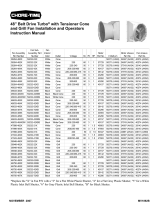
48" Belt Drive TURBO™ Fan
Item Description Part No.
1 Shutter 34914
2 Front Bearing Mount 35684
3 1” Shaft 34723
4 Rear Bearing Mount 35683
5 Motor (1-Phase, 50/60 Hz.) 35874
Motor (3-Phase, 50/60 Hz.) 36142
6 Sheave (1-Phase, 60 Hz.) 35333
Sheave (1-Phase, 50 Hz.) 8773
Sheave (3-Phase, 50 Hz.) 24697
7 Motor Mount Weldment Ring 35201
8 Spacer Ring 36824
Item Description Part No.
9 Segmented V-Belt 30374
10 Fan Blade Assembly 35950
11 8-1/4” Sheave 35009
12 Flangette 20191-1
13 Bearing 20191-2
14 Cone 35065
15 Cone Grill 35199
16 Shroud Grill 35200
17 48” Fan Shroud 35064
-- Shutter Clips 36560
-- Nylon Washers (for Shutter Clips)4856
-- Grommet 7256
Fan Motor
Module
Motor Specifications and Part Numbers
Motor Sheave
Part No.
H.P. Hz. Phase Voltage
Motor Part
No.
35687-LM -- -- -- -- -- 35333
35687-2 1 60 1 115/208-230 35874 35333
35687-3 1 50 1 115/220-240 35874 8773
35687-5 1 50 3 230/380-415 36142 24697
35687-6 1 60 3 230/380-415 36142 35333

48” Belt Drive TURBO™ Fan Installation Manual
•
Page 15
This page intentionally left blank.

48” Belt Drive TURBO™ Fan Installation Manual
•
Page 16
Contact your nearby Chore-Time distributor or representative for additional parts and information.
Chore-Time Equipment, A Division of CTB, Inc.
P.O. Box 2000, Milford, Indiana 46542-2000 U.S.A.
Phone: 219-658-4101
Printed in the U.S.A.
Made to work.
Built to last.™
THANK-YOU for purchasing a
Chore-Time Fan.
/