SSEEFF,, PPEEFF && GGEEFF EE
XXHHAAUUSSTT
FF
AANNSS
DD
IIRREECCTT
DD
RRIIVVEE
RREEAADD AANNDD SSAAVVEE TTHHEESSEE IINNSSTTRRUUCCTTIIOONNSS FFOORR FFUUTTUURREE RREEFFEERREENNCCEE
RREEAADD AANNDD SSAAVVEE TTHHEESSEE IINNSSTTRRUUCCTTIIOONNSS FFOORR FFUUTTUURREE RREEFFEERREENNCCEE
AASSSSEEMMBBLLYY IINNSSTTRRUUCCTTIIOONNSS
MMOODDEELLSS SSEEFF--1100 TTHHRROOUUGGHH SSEEFF--2244
CCoonntteennttss::
Pre-assembled guard mount fan, shutter, shutter
mounting hardware kit, package of mounting screws.
To mount shutter to fan assembly:
1. Shutter mounting hardware kit includes: 4 rubber vibration
isolators, 4 nylon inserts, 4 screws (#12 x 1”) and 4 rubberized
washers.
2. Insert screws into washers - rubber side down.
3. Place nylon inserts into square holes of corner gussets at
rear of shutter.
4. Place shutter face down (gusset side up). Center vibration
isolators over nylon inserts.
5. Place fan assembly on shutter so that wire hooks on fan
guard are centered over vibration isolators and nylon
inserts. Junction box must be positioned at bottom with
shutter blades opening upwards.
6. Secure fan assembly to shutter using screws and washers.
7. Ensure that fasteners are snug. Do not over tighten to
avoid stripping nylon inserts.
MMOODDEELL SSEEFF--3300
CCoonntteennttss::
Pre-assembled guard mount fan, shutter, shutter
mounting hardware kit, package of mounting screws.
To mount shutter to fan assembly:
1. Shutter mounting hardware kit includes: 4 rubber vibration
isolators, 8 rubber inserts, 8 screws (#8-32 x 11/2”) and 8
rubberized washers.
2. Insert screws into washers - rubber side down.
3. Place rubber inserts into round holes of corner gussets at
rear of shutter. It may be necessary to twist and push or tap
lightly to seat rubber inserts properly.
4. Place shutter face down (gusset side up). Center vibration
isolators over rubber inserts.
5. Place fan assembly on shutter so that wire hooks on fan
guard are centered over vibration isolators and nylon
inserts. Junction box must be positioned at bottom with
shutter blades opening upwards.
6. Secure fan assembly to shutter using screws and washers.
7. Ensure that fasteners are snug. Do not over tighten to
avoid pulling out rubber inserts.
MMOODDEELLSS PPEEFF--1
100 TTHHRROOUUGGHH PPEEFF--3300
CCoonntteennttss::
Pre-assembled panel mount fan.
MMOODDEELLSS GGEEFF--1100 TTHHRROOUUGGHH GGEEFF--3300
CCoonntteennttss::
Pre-assembled guard mount fan.
IINNSSTTAALLLLAATTIIOONN && MMAAIINNTTEENNAANNCCEE GGUUIIDDEE
CCAAUUTTIIOONN!! TTHHEESSEE FFAANNSS AARREE DDEESSIIGGNNEEDD FFOORR GGEENNEERRAALL
VVEENNTTIILLAATTIIOONN UUSSEE OONNLLYY.. DDOO NNOOTT UUSSEE TTOO EEXXHHAAUUSSTT CCOORRRROO--
SSIIV
VEE,, HHAAZZAARRDDOOUUSS OORR EEXXPPLLOOSSIIVVEE MMAATTEERRIIAALLSS AANNDD VVAAPPOORRSS..
BBEEFFOORREE IINNSSTTAALLLLAATTIIOONN
WWAARRNNIINNGG!! TTOO RREEDDUUCCEE TTHHEE RRIISSKK OOFF FFIIRREE,, EELLEECCTTRRIICCAALL
SSHHOOCCKK,, OORR IINNJJUURRYY TTOO PPEERRSSOONNSS,, PPLLEEAASSEE OOBBSSEERRVVEE TTHHEE
FFOOLLL
LOOWWIINNGG SSAAFFEETTYY PPRREECCAAUUTTIIOONNSS::
1.
TThhiiss ffaann hhaass rroottaattiinngg ppaarrttss!!
Turn impeller by hand to ensure
that it rotates freely.
2. Ensure that electrical service to fan is locked in the
“
OOFFFF
” position to prevent power from being switched on
accidentally. When the service disconnecting means
cannot be locked, securely fasten a prominent warning
device such as a tag to service panel.
3. Do not re-establish power supply until fan and activation
device are completely installed.
4. Installation work, including electrical wiring, must be
performed by a qualified person in accordance with all
applicable codes and standards, including local fire codes.
5. Check voltage at fan to see that it corresponds to fan motor
nameplate rating.
6. Fan is intended to be hard wired to a properly rated
electrical circuit, and must be properly grounded. Do
not use an extension cord.
7. Fan motor is equipped with thermal overload protection,
which causes fan to shut off automatically if motor overheats.
If this should happen, immediately disconnect and lock power
supply to fan.
DDoo nnoott aatttteemmpptt ttoo wwoorrk
k oonn ffaann wwiitthhoouutt ddiissccoonn--
nneeccttiinngg ppoowweerr ssuuppppllyy;; ffaann mmaayy rreessttaarrtt wwiitthhoouutt wwaarrnniinngg!!
8. Fan should not be turned on and off rapidly.
9. Do not use fan with a solid state speed control device.
10. Do not allow fan to become wet or damp.
11. Do not block air intake or exhaust from fan.
12. Do not allow foreign objects to enter fan and come in
contact with fan blades.
SSPPEEEEDD SSEELLEECCTTOORR SSWWI
ITTCCHH
Fan is equipped with either a 2-speed or 3-speed pull chain switch,
allowing user to select desired airflow. Pulling a speed selector
switch repeatedly will cause fan speed to cycle as follows:
22--SSppeeeedd SSwwiittcchh::
OFF – FIRST SPEED – OFF – SECOND SPEED – OFF
33--SSppeeeedd SSwwiittcchh::
OFF – HIGH – MEDIUM – LOW – OFF
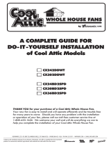
SSEEFF SSHHUUTTTTEERR MMOOUUNNTT FFAANN PPEEFF PPAANNEELL MMOOUUNNTT FFAANN GGEEFF GGUUAARRDD MMOOUUNNTT FFAANN