Page is loading ...

Thank You
The employees of Chore-Time Equipment would like to thank your for your recent Chore-Time purchase. If a
problem should arise, your Chore-Time distributor can supply the necessary information to help you.
48” Vanguard Belt Drive Fans
Installation and Operators Instruction Manual
Slant Wall Fan Cone Fan Box Fan
Panel Fan
Mv1700-001 02/02
Specifications and Part Numbers
Fan Part Numbers Motor Specifications and Part Numbers
Description
*Assembled
Part No.
Voltage HZ Phase HP Motor Part
No.
Motor Sheave
Part No.
Fan Sheave
Part No.
48" Standard Slant Wall
Fan
46991-482X 230 60 1 1 37729 8773 (AK30) 40274 (AK94)
46991-484X 208-230/460 60 3 1 40157 8773 (AK30) 40274 (AK94)
48" Hi-Cap Slant Wall Fan 47659-482X 115/230 60 1 1.5 47691 35333 (AK28) 28143 (AK84)
48" Vanguard Standard
Cone Fan
46868-482X 230 60 1 1 37729 8773 (AK30) 40274 (AK94)
46868-484X 208-230/460 60 3 1 40157 8773 (AK30) 40274 (AK94)
48'' Vanguard High
Efficiency Cone Fan
46992-482X 230 60 1 1 37729 1381 (AK27) 28143 (AK84)
46992-484X 208-230/460 60 3 1 40157 1381 (AK27) 28143 (AK84)
46992-488X 200/208 60 3 1 47680 1381 (AK27) 28143 (AK84)
48'' Vanguard Hi-Cap.
Cone Fan
46997-482X 115/230 60 1 1.5 47691 8773 (AK30) 40274 (AK94)
46997-484X 208-230/460 60 3 1.5 47693 8773 (AK30) 40274 (AK94)
48" Box Fan 38434-4820 230 60 1 1 37729 35333 (AK28) 42072
38434-4830 230 50 1 1 37729 8773 (AK30) 42072
38434-4840 208-230/460 60 3 1 40157 35333 (AK28) 42072
38434-4850 220-240/380-415 50 3 1 36142 24697 (MA33) 42072
38434-4860 230/380-415 60 3 1 36142 35333 (AK28) 42072
48" Panel Fan 40407-4820 230 60 1 1 37729 35333 (AK28) 42072
40407-4830 230 50 1 1 37729 8773 (AK30) 42072
40407-4840 208-230/460 60 3 1 40157 35333 (AK28) 42072
40407-4850 220-240/380-415 50 3 1 36142 24697 (MA33) 42072
40407-4860 230/380-415 60 3 1 36142 35333 (AK28) 42072
* Replace the "X" in Fan P/N with "1" for an Aluminum Shutter, "2" for a White Plastic Shutter, and “4” for Gray Plastic Shutter
Do Not operate these Fans with a variable speed control device. Operating static pressure should be less than 0.15 inches
water column.
MV1726BAugust 2003

Fan and Fan Framing Dimensions 48” Vanguard Belt Drive Fans Installation and Operators Instruction Manual
2
MV1726B
z
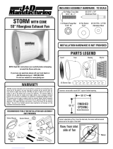
Planning the layout of the spacing between fans is
very important. Spacing too close together will
cause interference with the flanges. Allow a
minimum of 4" between framed openings of
adjacent fans. The Rough Opening dimensions for
Slant Wall and Cone Fans are shown at the right.
Fan and Fan Framing Dimensions
MV1700-012 02/02
5
3
1
2
4
1
2
3
4
5
6
6
7
7
Slant Wall Fan
Item Description
1 54.5” [138.4 cm]
2 58-1/4” [148 cm]
3 57” [144.8 cm]
4 33-3/8” [84.8 cm]
5 21” [53.3 cm]
6 5-3/4” [14.6 cm]
7 3-9/32" [8.3 cm]
Cone Fan
Item Description
1 54.5” [138.4 cm]
2 58-1/4” [148 cm]
3 57” [144.8 cm]
4 5-3/4” [14.6]
5 52-3/4” [134 cm]
6 Ø57" [Ø144.8 cm]
7 9-1/2" [24.13 cm]
MV1700-003 03/02
Spacing Between
Framed Openings 4"
55" [139.7 mm]
57.5" [146.1 mm]
MV1700-013 02/02
1
1
2
1
1
3
2
Box Fan
Item Description
1 54.5” [138.4 cm]
2 15.75” [40 cm]
3 24" [70 cm]
Panel Fan
Item Description
1 54.25” [137.8 cm]
2 20.75" [52.7 cm]
Rough Openings for Box and Panel Fans: Add 1/2" [12.7 mm] to Width and Height.

48” Vanguard Belt Drive Fans Installation and Operators Instruction Manual Fan Assembly
MV1726B
3
Assemble the Corner Flange Angles between the Fan Flange and framed opening.
1. Remove Cover Plate (Item 1, Figure below).
2. Install an electrical disconnect within reach of each Fan installed.
3. Remove the electrical knock-out nearest the Fan power supply outlet.
4. Install the Romex Connector (Item 3, Figure below) and cord through the knock-out selected before wiring the
motor. Connect the cord to the motor according to the wiring diagram on the motor. Verify that the motor is con-
nected for counter clockwise rotation (viewing the back of the motor, opposite the shaft end.)
Follow local, state, and national electrical codes for wiring.
5.Attach the cord to the Top Panel of the Fan using the Cord Clip (Item 4, Figure below) to keep the cord off the
Shutter.
6.Allow enough slack in the cord to form a "drip loop", (Item 2, Figure below), for moisture to fall away from the
cord and not into the motor.
7.Remove the slack in the cord between the Cord Clip and the Romex Connector and then tighten the Romex Con-
nector.
Fan Assembly
1
4
3
3
1
Side View of Fan Mounting
Front View of Flange Angle and Fan Assembly
Flange Angles are to be placed between the Building
and the Fan Flange
4
4
4
2
2
MV1700-004 03/02
Item Description
1 Fan Assembly
2 Side Wall of Building
3 1/4” x 1-3/4” Lag Screw
4 Corner Flange Angles
Wiring
1
2
3
4
MV1700-019 03/02
Item Description Part No.
1 Cover Plate
2 "Drip Loop"
3 Romex Connector 1317
4 Cord Clip 7242

Shutter Part Numbers 48” Vanguard Belt Drive Fans Installation and Operators Instruction Manual
4
MV1726B
The Bottom Panel is designed with 3 tabs to hold the Shutter. Slide the bottom of the Shutter into position in the
Bottom Panel Slots, lean the Shutter back and lock it in place by rotating the Shutter Clips. Check the Shutter for
proper operation; The shutter must be able to open and close freely
Carefully read all safety messages in this manual and on your equipment safety signs. Follow recommended
precautions and safe operating practices. Keep safety signs in good condition. Replace missing or damaged safety
signs.
DANGER: Electrical Hazard
Disconnect electrical power before inspecting or servicing equipment unless
maintenance instructions specifically state otherwise. Ground all electrical equipment
for safety. All electrical wiring must be done by a qualified electrician in accordance
with local and national electric codes. Ground all non-current carrying metal parts to
guard against electrical shock. With the exception of motor overload protection,
electrical disconnects and over current protection are not supplied with the equipment.
DANGER: Rotating Fan Blade
Keep Hands away. Disconnect power before servicing. Fan may start automatically.
Do not operate the Fan without the screens in place. Disregard to these things will cause
serious injury including death.
Shutter Part Numbers
MV1700-016 03/02
1 2
4
3
4
5
Item Description Part No.
1 Shutter Aluminum (complete) 38260
2 White Plastic Shutter (complete) 38029
Gray Plastic Shutter (complete) 46716
3 Push Nut 1/4'' 38032
4 Shutter Pivot Rod 38702-4
5 White Shutter Louver 38038-4
Gray Shutter Louver 46715-4
Shutter Installation
Safety Information
2
1
MV1700-008 03/02
Item Description
1 Bottom Panel Slot
2 Shutter Clips

48” Vanguard Belt Drive Fans Installation and Operators Instruction Manual Maintenance
MV1726B
5
Disconnect Power Prior To Maintaining Or Cleaning The Fan. The fan may start automatically causing serious
injury or death.
• Service and repair of fans should be done only by a qualified technician.
• Keep the fan clean for maximum life and best performance. Avoid spraying water on fan shaft bearings.
• Periodically check the V-Belt and replace if necessary. A bad Belt will cause
a substantial drop in Fan performance or it can break and cause Fan failure.
If a Belt rides below the Sheave edge, replace the belt. (See Figure at the
Right)
• Keep Shutters, Blades, and Housing clear of obstacles for best air perfor-
mance.
• The motor and fan shaft bearings are pre-lubricated. Grease zerks are provided on the fan shaft bearings for instal-
lations where re-lubrication is needed. Re-lubrication is required once annually or if water contacts the Bearings.
Add only a small amount of grease to purge impurities out of the bearing seals.
• Use only high quality lithium soap base grease and clean all dirt from zerk before applying grease. Chore-Time
recommends using Shell Alvania # 2 in the fan shaft bearings.
•Check Drive Belt Alignment: The Figure below shows how to properly align the belt and adjust the tension to
insure the best installation and Fan life.
•Belt must be vertical to obtain maximum belt life.
•Measure from the Post to the belt as shown to make sure that there is equal distance. Lay a straight
edge across the posts to get the measurement if necessary. (See Figure below)
•Tighten the 5-16-18 x 5.5" Bolt (Item 1, Figure below) until the measurement from the end of the Bolt to the
Bottom Spring Cap (Item 3) is 5/8" [16 mm] as shown in the Figure below.
•Check Sheaves for wear. Replace if a Sheave groove is worn. (See Figure
to the Right)
Maintenance
Good Belt
Bad Belt
MV1726-001 05/02
Bad Belt
(Needs Replaced)
5/8" [16 mm]
1
3
Equal
Distance
2
4
5
MV1700-017 03/02
Belt Alignment
Item Description
1 5/16-18 x 5.5" Bolt
2 Spring
3 Bottom Spring Cap
4 Post
5 Belt
Worn Sheave
(Needs Replaced)
Good Sheave
Bad Sheave
Mv1726-002 05/02

Itemized Parts 48” Vanguard Belt Drive Fans Installation and Operators Instruction Manual
6
MV1726B
Itemized Parts
36 37 38
4
9
12
36 37 38 39
16
8
5
2
44
23
1
15
3
31
6
10
13
41
2 23
18
18
20
22
23 26
24
19
38 32
11
2 23
40
33
30
33
Cone Fan Version
Slant Wall Version
Deep Box Version
Panel Version
34
45
4 Places
MV1700-010 03/02
2
23
7
25
27
35
21
28
29
43
46
2
3
14
27

48” Vanguard Belt Drive Fans Installation and Operators Instruction Manual Part Numbers
MV1726B
7
Part Numbers
Slant Wall Fan Cone Fan EZ Box Fan Panel Fan
Standard
46991-48XX
Hi-Cap
47659-48XX
Standard
46868-48XX
High
Efficiency
46992-48XX
Hi-Cap
46997-48XX
Standard
38434-48X0
Standard
40407-48X0
Itm Description Qty
Part
No.
Qty
Part
No.
Qty
Part
No.
Qty
Part
No.
Qty
Part
No.
Qty
Part
No.
Qty Part No.
1* Motor 1 Varies 1 Varies 1 Varies 1 Varies 1 Varies 1 Varies 1 Varies
2 5/16-18 x .625 Car. Bolt 32 8282 32 8282 32 8282 32 8282 32 8282 32 8282 20 8282
3 5/16-18 Hex Lock Nut 3 2148 3 2148 3 2148 3 2148 3 2148 3 2148 3 2148
4 48'' Top Panel 1 43667 1 43667 1 43670 1 43670 1 43670
5 48" Bottom Panel 1 43668 1 43668 1 43671 1 43671 1 43671
6 48" Side (RH) Panel 1 43669-2 1 43669-2 1 43672-2 1 43672-2 1 43672-2
7 48" Side (LH) Panel 1 43669-1 1 43669-1 1 43672-1 1 43672-1 1 43672-1
8 48'' Fan Shroud 1 37583 1 37583 1 37583 1 37583 1 37583 1 37583 1 37583
9 48'' Fan Shutter Mt. Brace 1 43673 1 43673 1 43673 1 43673 1 43673
10 48" Fan Post 2 43688 2 43688 2 43688 2 43688 2 43688 2 43688 2 43688
11 Motor Mount Pivot Plate 1 43713 1 43713 1 43713 1 43713 1 43713 1 43713 1 43713
12 Pivot Plate Mntg. Brkt. 1 46444 1 46444 1 46444 1 46444 1 46444 1 46444 1 46444
13 Z-Motor Mounting Brkt. 1 46445 1 46445 1 46445 1 46445 1 46445 1 46445 1 46445
14 ST BD Module Bushing 2 38896 2 38896 2 38896 2 38896 2 38896 2 38896 2 38896
15 Spring 1 43715 1 43715 1 43715 1 43715 1 43715 1 43715 1 43715
16 48'' Fan Blade 1 28140 1 46748 1 28140 1 45932 1 46748 1 28140 1 28140
17
18 1/4 x 1 x 1/8 Square Key 2 2419-2 2 2419-2 2 2419-2 2 2419-2 2 2419-2 2 2419-2 2 2419-2
19 Shaft 1 43691 1 43691 1 43691 1 43691 1 43691 1 43691 1 43691
20 Rear Bearing Mount Plate 1 43690 1 43690 1 43690 1 43690 1 43690 1 43690 1 43690
21 Front Bearing Mnt. Plate 1 43689 1 43689 1 43689 1 43689 1 43689 1 43689 1 43689
22 1" Bore Cast Fl. Bearing 2 43654 2 43654 2 43654 1 43654 1 43654 2 43654 2 43654
23 5/16-18 H. Ser. Flg. Nut 30 8490 34 8490 30 8490 1 8490 1 8490 30 8490 22 8490
24* Driven Sheave 1 Varies 1 Varies 1 Varies 1 Varies 1 Varies 1 Varies 1 Varies
25 Corner Flange Angle 4 44284 4 44284 4 44284 4 44284 4 44284
26 5/16-18 x 1.25 Car. Bolt 4 34885-2 4 34885-2 4 34885-2 4 34885-2 4 34885-2 4 34885-2 4 34885-2
27 .375 x .875 x .078 Wshr. 3 546 3 546 3 546 3 546 3 546 3 546 3 546
28 Danger Decal 2 2527-50 2 2527-50 2 2527-50 2 2527-50 2 2527-50 2 2527-50 2 2527-50
29 36" S/W Cone Fan Decal 1 Varies 1 Varies 1 Varies 1 Varies 1 Varies 1 Varies 1 39002-118
30 EZ Fan Screen Clip 16 38891 16 38891 32 38891
31 Spring Coil Cap 2 44002 2 44002 2 44002 2 44002 2 44002 2 44002 2 44002
32 #10-16 x .50 HxWh Screw 22 3037 22 3037 16 3037 16 3037 16 3037
33 Wire Screen 1 6023-22 1 6023-22 1 6023-22
34 48" BD Fan Inlet Screen 1 45865
35 5/16-18 x 5.5" Bolt 1 4412-24 1 4412-24 1 4412-24 1 4412-24 1 4412-24 1 4412-24 1 4412-24
36 SS Shutter Clip 5 36729 5 36729 5 36729 5 36729 5 36729
37 Nylon Washer 5 4856 5 4856 5 4856 5 4856 5 4856
38 3/16" x 3/8" Pop Rivet 9 2569 9 2569 9 2569 9 2569 9 2569
39 .227 x .515 x .065 Wshr. 2 2955-19 2 2955-19 2 2955-19 2 2955-19 2 2955-19
40* Cast Iron Sheave 1 Varies 1 Varies 1 Varies 1 Varies Varies 1 Varies 1 Varies
41 AX57 V Belt 1 46967 1 46967 1 46967
AX55 V Belt 1 46990 1 46990
AX56 V Belt 1 43816 1 43816
42 Grill 1 37630 1 37630 1 37630
43 48" Fan Cone Panel 4 37805 4 37805 4 37805
44** 48" Shutter 1 Varies 1 Varies 1 Varies 1 Varies 1 Varies
45 48" Box Fan Panel 4 38391
46 Cone Mounting Bracket 4 37806 4 37806 4 37806
* See Motor Specifications Chart on Page 1
** See Shutter Part Numbers on Page 4

Warranty Information 48” Vanguard Belt Drive Fans Installation and Operators Instruction Manual
8
MV1726B
Chore-Time Equipment (“Chore-Time”) warrants each new Chore-Time product manufactured by it to be free
from defects in material or workmanship for one year from and after the date of initial installation by or for the
original purchaser. If such a defect is found by the Manufacturer to exist within the one-year period, the
Manufacturer will, at its option, (a) repair or replace such product free of charge, F.O.B. the factory of manufacture,
or (b) refund to the original purchaser the original purchase price, in lieu of such repair or replacement. Labor costs
associated with the replacement or repair of the product are not covered by the Manufacturer.
Conditions and Limitations
1. The product must be installed by and operated in accordance with the instructions published by the Manufacturer
or Warranty will be void.
2. Warranty is void if all components of the system are not original equipment supplied by the Manufacturer.
3. This product must be purchased from and installed by an authorized distributor or certified representative thereof
or the Warranty will be void.
4. Malfunctions or failure resulting from misuse, abuse, negligence, alteration, accident, or lack of proper
maintenance shall not be considered defects under the Warranty.
5. This Warranty applies only to systems for the care of poultry and livestock. Other applications in industry or
commerce are not covered by this Warranty.
The Manufacturer shall not be liable for any Consequential or Special Damage which any purchaser may suffer
or claim to suffer as a result of any defect in the product. “Consequential” or “Special Damages” as used herein
include, but are not limited to, lost or damaged products or goods, costs of transportation, lost sales, lost orders,
lost income, increased overhead, labor and incidental costs and operational inefficiencies.
THIS WARRANTY CONSTITUTES THE MANUFACTURER’S ENTIRE AND SOLE WARRANTY AND THIS
MANUFACTURER EXPRESSLY DISCLAIMS ANY AND ALL OTHER WARRANTIES, INCLUDING, BUT NOT
LIMITED TO, EXPRESS AND IMPLIED WARRANTIES AS TO MERCHANTABILITY, FITNESS FOR PARTICULAR
PURPOSES SOLD AND DESCRIPTION OR QUALITY OF THE PRODUCT FURNISHED HEREUNDER.
Chore-Time Distributors are not authorized to modify or extend the terms and conditions of this Warranty in any
manner or to offer or grant any other warranties for Chore-Time products in addition to those terms expressly stated
above. An officer of CTB, Inc. must authorize any exceptions to this Warranty in writing. The Manufacturer reserves
the right to change models and specifications at any time without notice or obligation to improve previous models.
Made to work.
Built to last.
Contact your nearby Chore-Time distributor or representative for additional parts and information.
CTB Inc.
P.O. Box 2000 • Milford, Indiana 46542-2000 • U.S.A.
Phone (574) 658-4101 • Fax (877) 730-8825
E-Mail: [email protected] • Internet: http//www.ctbinc.com
Printed in the U.S.A.
Warranty Information
/