Toro Counterweight Kit, RT1200 Trencher Installation guide

Type
Installation guide

This manual is also suitable for

FormNo.3395-684RevA
CounterweightKitandCounterweightandReelKit
RT1200Trencher
ModelNo.25458
ModelNo.25458E
ModelNo.25459
ModelNo.25459E
InstallationInstructions
Safety
WARNING
CALIFORNIA
Proposition65Warning
ThisproductcontainsachemicalorchemicalsknowntotheStateofCaliforniato
causecancer,birthdefects,orreproductiveharm.
Installation
LooseParts
Usethechartbelowtoverifythatallpartshavebeenshipped.
Description
Qty.
Use
Nopartsrequired
Preparethemachine.
Mountingframe
1
Bolt(1-1/4x3-1/2inch)
4
Washer(1-1/4inch)
4
Installthemountingframe.
Counterweight
21
Rod1
Washer(5/8inch)
2
Locknut(5/8inch)
2
Strutpad
2
Installthecounterweights.
©2015—TheToro®Company
8111LyndaleAvenueSouth
Bloomington,MN55420
Registeratwww.T oro.com.
OriginalInstructions(EN)
PrintedintheUSA
AllRightsReserved
*3395-684*A
Description
Qty.
Use
Reelcollar2
Spindle
1
Hexbolt(5/8x1-1/2inch)
2
Bolt(3/8x5-1/2inch)
2
Washer2
Nut2
Cylinderpin
2
Retainingring4
Clevisepin
4
Hairpin4
Plowlift
2
Hydraulichose4
Teetting
2
Hexbolt(5/16x1-3/8inch)
2
Coverplate
2
Hosemount2
Rockerswitch1
Installthereel(models25459and25459Eonly).
PreparingtheMachine
1.Movethemachinetoalevelsurface.
2.Settheparkingbrakeandlowertheattachmentsto
theground
3.Stoptheengineandremovethekey.
4.Ifafront-mountedattachmentsuchasthebackhoeis
installedonthemachine,removetheattachment;refer
totheOperator’sManualfortheattachment.
2
InstallingtheMountingFrame
Note:Yourliftingequipmentmusthavealiftcapacityof
136kg(300lb).
Note:Removeallcounterweightkithardwareandweights
fromthemountingframepriortoinstallationofthe
counterweightkit.Eachcounterweightweighsapproximately
30kg(66lb).
1.Removethe2locknuts(5/8inch),2washers(5/8
inch),androdthatsecurethecounterweightstothe
mountingframe.
Note:Retainthelocknuts,washers,androdfor
installationinstep3ofInstallingtheCounterweights
(page4).
2.Usingtheliftingequipment,removethecounterweights
fromthemountingframe.
3.Useliftingequipmenttoraiseorlowerthemounting
frameuntiltheholesinthemountingframealignwith
theholesinthemachine;refertoFigure1.
g025307
1
2
3
Figure1
1.Mountingframe3.Hole(machinechassis)
2.Hole(mountingframe)
4.Applymedium-grade(serviceremovable)
thread-lockingcompoundtothethreadsofthe4bolts
(1-1/4x3-1/2inch).
5.Installtheboltsandwasherstofastenthemounting
frametothemachine(Figure2).
Note:Hand-tightenthebolts.
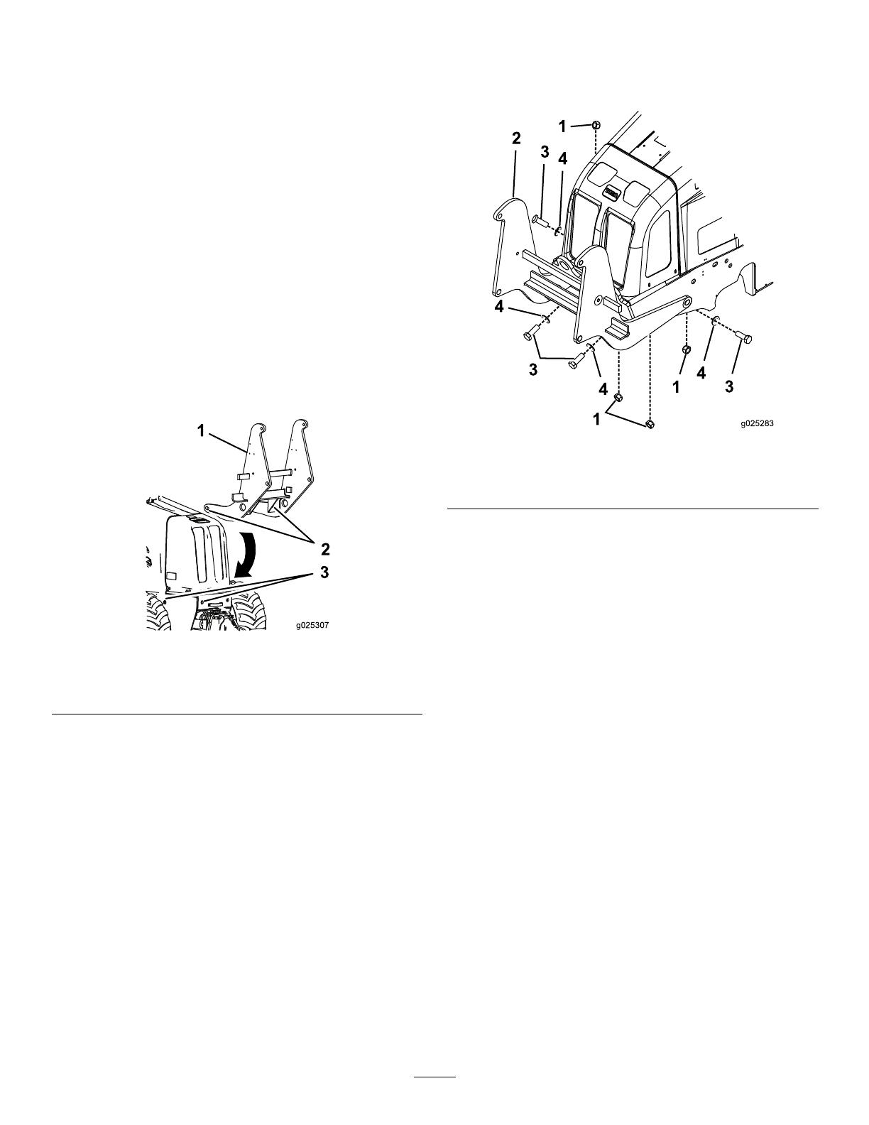
1
1
1
2
4
4
4
3
3
3
4
g025283
Figure2
1.Nut3.Bolt
2.Mountingframe
4.Washer
6.Torqueall4boltsto1220to1491N-m(900to1100
ft-lb).
7.Removetheliftingequipmentfromthemounting
frame.
3
InstallingtheCounterweights
1.Ifnotalreadyinstalled,installastrutpadtotheinside
ofeachsideofthemountingframeusingtheadhesive
sideofeachstrutpad.
Figure3
1.Strutpad
2.Usetheliftingequipmenttoliftandinstallthe
counterweightsontothemountingframe(Figure4).
Note:Install3counterweightsoneachsideofthe
frameand15counterweightsinthecenter.
Figure4
1.Mountingframe2.Counterweight
3.Securethecounterweight(s)tothemountingframe
withtherod,washers,andlocknutsthatyouremoved
instep1ofPreparingtheMachine(page2);referto
Figure5.
Note:Donotovertightenthenuts.Tightenthenuts
onlyenoughtopreventthewashersfromrattling.
Figure5
1.Locknut3.Rod
2.Washer
4
InstallingtheReel
Models25459and25459E
1.Assemblethespindle(Figure6).
Figure6
1.Reelcollar
3.Hexbolt(5/8x1-1/2inch)
2.Spindle
4.Washer
2.Mounteachendofthespindletothereelcarrierarm
asshowninFigure7,andtorquethefastenersto37
to45N-m(37to33ft-lb).
Figure7
Rightendofspindleshown
1.Nut
3.Stopblock
2.Washer
4.Bolt(3/8x5-1/2inch)
3.Mountthereelcarrierarmtothecounterweightframe
using4retainingringsand2pins(Figure8).
Figure8
1.Retainingring2.Pin
4.Mounttheliftcylinderstothemachineusing4hair
pinsand4clevispins(Figure9).
Figure9
1.Hairpin
3.Liftcylinders
2.Clevispin
5
5.Installthehydraulichosesandteettingstothelift
cylindersandthemachine(Figure10andFigure11).
Note:Thehydraulicportonthemachineislocated
onthebottomrightsideofthefrontofthemachine.
Note:Connectthehosesbycorrespondingletters(A,
B,C,andD)inFigure10andFigure11.
g025333
1
2
3
4
Figure10
1.HoseA
3.HoseC
2.HoseB4.HoseD
4
3
1
2
g025332
5
5
Figure11
1.HoseA4.HoseD
2.HoseB
5.Teetting
3.HoseC
6
6.Installahoseclamptotheinsideofeachsideofthe
mountingframe(Figure12).
Figure12
1.Hoseclamp
3.Hexbolt(5/16x1-3/8inch)
2.Coverplate
7.Onthecontrolpanel,removethedash-switchplug,
transferthewiringharnessconnectortotherocker
switch,andinstalltherockerswitch(Figure13).
Note:Ifthewiringharnessisnotattachedtothehole
plug,reachunderthecontrolpaneltondthewiring
harnessandconnectittotheswitch.
Figure13
1.Dash-switchplug2.Rockerswitch
7
  • Page 1 1
  • Page 2 2
  • Page 3 3
  • Page 4 4
  • Page 5 5
  • Page 6 6
  • Page 7 7
  • Page 8 8

Toro Counterweight Kit, RT1200 Trencher Installation guide

Type
Installation guide
This manual is also suitable for

Ask a question and I''ll find the answer in the document

Finding information in a document is now easier with AI