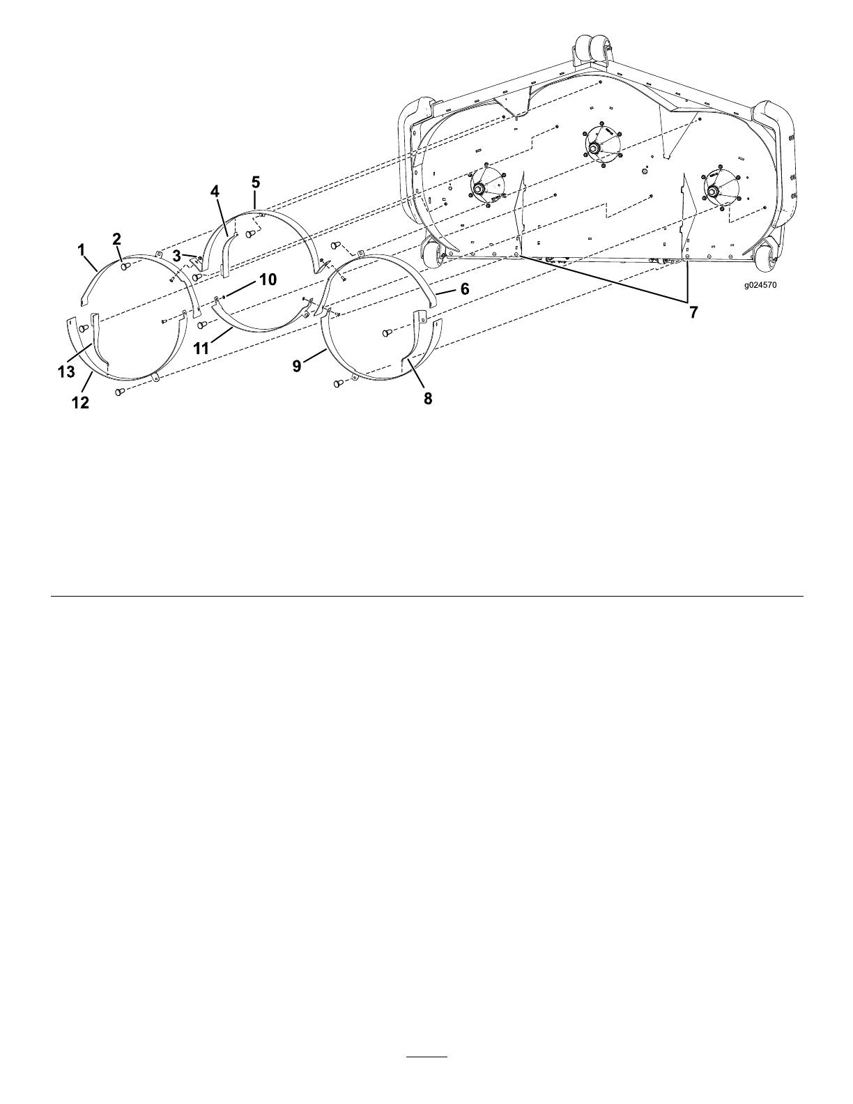
Toro Baffle Kit, 60in Rear Discharge Z Master Mowers Installation guide

Category
Lawnmowers
Type
Installation guide

This manual is also suitable for

FormNo.3381-168RevB
BafeKit
60inor72inRearDischargeZMaster
®
Mowers
ModelNo.125-9305
ModelNo.125-9310
InstallationInstructions
WARNING
CALIFORNIA
Proposition65Warning
ThisproductcontainsachemicalorchemicalsknowntotheStateofCaliforniato
causecancer,birthdefects,orreproductiveharm.
1
RemovingtheOriginal
Hardware
NoPartsRequired
Procedure
1.Ensurethatallmovingpartshavestopped,theparking
brakeisengaged,andthekeyhasbeenremoved.
2.Raisethefrontofthemachineandsupportitwithjack
stands.
WARNING
Raisingthemowerdeckforserviceor
maintenancerelyingsolelyonmechanical
orhydraulicjackscouldbedangerous.The
mechanicalorhydraulicjacksmaynotbe
enoughsupportormaymalfunction,allowing
theunittofall,whichcouldcauseinjury.
Donotrelysolelyonmechanicalorhydraulic
jacksforsupport.Useadequatejackstands
orequivalentsupport.
Important:Theright-handbladeonthismower
deckiscounter-rotatingandusesaleft-hand
threadedbladebolt.
3.Removethebladesandretainthemforremovalofthe
bafekit.
4.Ifthemowerhasbeenused,scrapetheundersideof
themowerdeckclean.
5.Removethehardwarethatplugstheexposedmounting
holesinthedeck.
For60-inchdecks,removethe6hex-socketscrews
(5/16-18x3/4inch)andangednylocnuts
pluggingtheexposedmountingholesinthedeck
(
Figure1).
Note:Retainthesepartsforfutureuse.
Figure1
60-inchdeckshown
1.Partsthatneedtoberetained
For72-inchdecks,removethe4hex-socketscrews
(5/16-18x3/4inch),theangednutsplugging
theexposedmountingholesinthedeck,andthe
inboard-tire-apfasteneroneachside(
Figure2).
Note:Retainthesepartsforfutureuse.
©2014—TheToro®Company
8111LyndaleAvenueSouth
Bloomington,MN55420
Registeratwww.Toro.com.
OriginalInstructions(EN)
PrintedintheUSA.
AllRightsReserved
*3381-168*B
Figure2
72-inchdeckshown
1.Socketscrew2.Carriagebolt
6.Removeandretainthe2rearcarriagebolts(3/8-16x
2-1/4inches)andangenutsfromeachsidewithin
thecuttingchamberthatattachthesidebumpersto
thedecksides.
2
InstallingtheBafes
Partsneededforthisprocedure:
1
Frontright-handbafe
1
Rearright-handbafe
1
Frontcenterbafe
1
Rearcenterbafe
1
Frontleft-handbafe
1
Rearleft-handbafe
1
Right-handkickerbafe
1
Centerkickerbafe
1
Left-handkickerbafe
2
Locknut(3/8-16)
14
Carriagebolt(3/8-16x7/8inch)—60-inchmodelonly
12
Carriagebolt(3/8-16x7/8inch)—72-inchmodelonly
16
Flangenut(3/8-16)—60-inchmodelonly
10
Flangenut(3/8-16)—72-inchmodelonly
2
Carriagebolt(5/16-18x1inch)—72-inchmodelonly
2
Flangenut(5/16-18)—72-inchmodelonly
Procedure
Note:Determinetheleftandrightsidesofthemachine
fromthenormaloperatingposition.
2
Figure3
1.Frontright-handbafe8.Left-handkickerbafe
2.Carriagebolt9.Rearleft-handbafe
3.Flangenut10.Locknut
4.Centerkickerbafe11.Rearcenterbafe
5.Frontcenterbafe12.Rearright-handbafe
6.Frontleft-handbafe13.Right-handkickerbafe
7.Carriagebolt(5/16-18x1inch)andangenut
(5/16-18)—72-inchmodelonly
1.Installthefrontouterbafesbyusingonecarriage
bolt(3/8-16x7/8inch)andoneangenut(3/8-16)
perbafe(Figure3).
Note:Tohelpalignthebafes,looselyinsertthe
carriagebolts(3/8-16x2.5inches)andangenuts
(3/8-16)throughthesideofthebafesandthebumper
(Figure6).
2.Installthefrontcenterbafewith3carriagebolts
(3/8-16x7/8inch)andangenuts(3/8-16)asshown
inFigure3.
3.Installtherearouterbafesbyusingonecarriagebolt
(3/8-16x7/8inch)andoneangenut(3/8-16)per
bafeasshownin
Figure3.
Note:Tohelpalignthebafes,looselyinsertthe
carriagebolts(3/8-16x2.5inches)andangenuts
(3/8-16)throughthesideofthebafesandthebumper
(Figure6).
Note:Thefrontouterbafesinstallbetweenthe
rear-bafetabs.
Note:The72-inchmodelusesonecarriagebolt
(5/16-18x1inch)andoneangenut(5/16-18)inthe
rearoftheright-handbafe,theleft-handbafe,and
theinnermostsquareholeontheinboardtireapon
eachside(
Figure3).
4.Installtherearcenterbafeusing2carriagebolts
(3/8-16x7/8inch)and2locknuts(3/8-16)asshown
inFigure4.
Note:Thisbafeinstallsbetweenthefrontouter
bafeanges(Figure4).
Note:Wherethefrontouterbafes,therearouter
bafes,andtherearcenterbafecometogether,install
2carriagebolts(3/8-16x7/8inch)andthe2locknuts
(3/8-16)asshowninFigure4.
3
Figure4
1.Carriagebolt(3/8-16x7/8
inch)
3.Frontbafeange
2.Rearcenterbafe4.Locknut(3/8-16)
5.Tightenallofthehardware.
6.Usingonecarriagebolt(3/8-16x7/8inch)andone
angenut(3/8-16),installthecorrectkickerbafeto
eachchamber(Figure1).
Note:Thehookedendofeachkickerbafeattaches
totheslotinthechamberbafe(Figure5).
Note:Youmayneedtoloosenthematingbafeto
allowthehookedendofthekickerbafetotcorrectly.
Figure5
1.Slot
2.Hookedend
3
SecuringtheBumpersandthe
RightandLeft-handBafeto
theMowerDeck
Partsneededforthisprocedure:
4
Carriagebolt(3/8-16x2.5inches)
4
Flangenut(3/8-16)
Procedure
Note:Youmayneedtoloosenthematingbafeandkicker
bafetoallowthebumperboltstobeinstalled.
1.Insert2carriagebolts(3/8-16x2.5inches)oneach
sidethroughtherightandleft-handbafeandthe
bumpers(Figure6).
Figure6
1.Flangenut(3/8-16)4.Left-handbafe
2.Bumper
5.Right-handbafe
3.Carriagebolt(3/8-16x2.5
inches)
2.Securethecarriageboltswith2angenuts(3/8-16)on
eachside(Figure6).
3.Torquethecarriageboltsandangenutsto12.4to
14.7N-m(110to130in-lb).
4
4
InstallingtheBlades
Partsneededforthisprocedure:
1
20.5-inchrotaryblade(red)—60-inchmodelonly
2
20.5-inchlow-owblade(black)—60-inchmodelonly
1
24.5-inchrotaryblade(red)—72-inchmodelonly
2
24.5-inchlow-owblade(black)—72-inchmodelonly
Procedure
Note:Determinetheleftandrightsidesofthemachine
fromthenormaloperatingposition.
Important:Theright-handbladeonthismowerdeck
iscounter-rotatingandusesaleft-handthreadedblade
bolt.
1.Installtheredreverse-rotationbladeontothe
right-handspindle(Figure7).
Note:Ensurethatthecurvedpartofthebladeis
pointingupwardtowardtheinsideofthemowerdeck
toensurepropercutting.
Note:Ensurethatthecurved-washerconeisinstalled
towardsthebolthead(
Figure8).
Figure7
1.Centerspindle4.Centerblade(black)
2.Left-handspindle
5.Right-handspindle
3.Left-handblade(black)6.Right-handblade(red)
Figure8
Leftandcenterspindleshown
1.Sailareaoftheblade3.Curvedwasher
2.Blade4.Bladebolt
2.Installthe2blackbladesontothecenterandleft-hand
spindle(Figure7).
3.Torquethebladeboltsto115to150N-m(85to110
ft-lb).
Note:Carefullyandslowlyrotateeachblade360°
byhandtoensurethatthereisclearancebetweenthe
bladesandthebafes.Adjustthebafesslightlyif
interferenceisfound.
WARNING
Incorrectinstallationofthebladesor
componentsusedtoretainthebladescanbe
dangerous.Failuretousealloftheoriginal
componentsandensuringthateverythingis
assembledasshowncouldallowabladeora
bladecomponenttobethrownoutfromunder
thedeck,resultinginseriouspersonalinjury
ordeath.
Alwaysinstallthebladesandthe
blade-retaininghardware;refertothe
Operator’ s Man ual
.
4.Carefullyremovethejackstandsandlowerthemachine
totheground.
5
5
ConvertingBacktoRear
Discharge
NoPartsRequired
Procedure
1.Stopengineandwaitforallmovingpartstostop,
engagetheparkingbrake,removethekey,and
disconnectthenegativebatterycable.
2.Removethenish-cutbafesandthekickerbafes,
andretainallofthehardware.
3.Replacethenish-cutbladeswithstandardblades.
4.Installthe5/16-18x3/4-inchhex-socketscrewsand
theangenutsintheholesontopofthedeckwith
theboltheadunderneath.
Note:Allopenholesnotcoveredbybeltshieldsorthe
framemustbepluggedtopreventsandand/orother
smallobjectsfrombeingthrownupthroughthedeck.
6
Notes:
7
1 / 1

Toro Baffle Kit, 60in Rear Discharge Z Master Mowers Installation guide

Category
Lawnmowers
Type
Installation guide
This manual is also suitable for

Ask a question and I''ll find the answer in the document

Finding information in a document is now easier with AI

Ask the document