Page is loading ...

sec.2
−−−−
1
2 VOICE - Technical Manual
START
SECTION 2
(REV. B)
SYSTEM
INSTALLATION AND
ACTIVATION
SYSTEM INSTALLATION 2
REGULATIONS AND NOISE IMMUNITY ..........................................2
SYSTEM POWER SUPPLY ..............................................................2
ALLOWED CABLES .........................................................................2
WIRING .............................................................................................2
MAX. DISTANCES AND EXTENSIONS ...........................................3
SYSTEM ACTIVATION 12
LINE TERMINATIONS SETTING.....................................................12
DEVICES CONFIGURATION ..........................................................12
Call stations ................................................................................12
Apartment stations (door phones and brackets) ........................13
Column interfaces ......................................................................14
POWER-UP AND SUPPLY VOLTAGE CHECK ..............................14
SYSTEM CHECK ............................................................................14
How to split the system .............................................................. 14
ASSOCIATION OF DOOR UNITS BUTTONS TO USERS .............. 15
Main doors unit ...........................................................................15
Secondary doors unit .................................................................16
BASIC FUNCTIONAL CHECK ........................................................16
OPTIONAL PROGRAMMING .........................................................16
Download from www.urmet.com Technical Manuals area.
SECTION CONTENTS

2
−−−−
sec.2
2 VOICE - Technical Manual
START
SYSTEM INSTALLATION AND ACTIVATION
SYSTEM INSTALLATION
REGULATIONS AND NOISE IMMUNITY
All devices must be perfectly installed and wired, observing national
installation rules.
Pay attention to power supply units and transformers, that must be
placed in suitable electrical service panels and provided with properly
dimensioned protection switches and circuit breakers.
All system devices are compliant with EC Directives concerning
electromagnetic compatibility and electric safety. The power supply
unit is also provided with IMQ and VDE approval marks.
However, to improve noise immunity, do not lay system wires
near power supply cables, that generate strong electromagnetic
fi elds.
If the above described rules are not observed, the following
problems, typical for all video door phone systems, could occur with
unforeseeable frequency and importance:
Errors during data transmission among devices, with possible
problem when performing calls.
Low image quality: loss of details, double vision, …
Noisy video image.
Noisy audio signal.
SYSTEM POWER SUPPLY
In brief, to evaluate the number of system power supply units Ref.
1083/20A, consider that 1 power supply unit is enough for a one-
column system with 1 or 2 call stations, up to 128 apartment stations
and 1 column interface.
In systems with more than one column, 1 power supply must be
added for each column.
In systems with more than one main call station and door units
interface, add one power supply.
ALLOWED CABLES
The 2VOICE bus is NON polarized. The cable (Ref.1083/90 or
Ref.1083/92) has been designed to ensure the maximum distance
and dimensions of the system. Because this cable is twisted, a good
noise immunity is ensured.
For system max. extensions and types when different kinds of
cables are used, see the next paragraphs.
WARNING ! If multi-pole cables are used, it is absolutely forbidden
to short-circuit several conductors in order to increase the cable
section.
For long distance branches, it is suggested to reduce to the
minimum joint points between cables. For joints, use devices
ensuring a good and lasting connection between cables,
protecting the joint against humidity and bad weather.
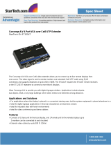
WIRING
To improve noise immunity, do not lay system wires near power
supply cables, that generate strong electromagnetic fi elds.
Power supply
cable
Power supply
cable
2VOICE
cables
2VOICE
cables
NO YES
Besides main devices (for allowed distances, see the paragraph “Max.
distances and dimensions”, the system can be composed by other
additional devices. To connect these devices, the max. distances
(in metres) are shown in the following tables, provided that suitable
sections cables are used.
•
•
•
•
§
§
SYSTEM INSTALLATION
REGULATIONS AND NOISE IMMUNITY - SYSTEM POWER SUPPLY
ALLOWED CABLES - WIRING
SYSTEM INSTALLATION
Cable section [mm
2
]
From call station
to …
0,28 0,5 1
Pedestrian electric lock 10m 20m 30m
Gate opening control unit 30m 50m 100m
Entrance hall button 25m
Door sensor 25m
Surveillance camera switch 300m
Cable section [mm
2
]
From call station
to …
0,75 1,5 2,5
Name holder lighting transformer 100m 200m 300m
Cable section [mm
2
]
From ap. stations to…
0,28 0,5
1
Floor call button (CP) 10m
Additional ringer (S+,S-) 10m
Follow the instructions below for a correct wiring, in order not to
change cables specifi cations:
Use only the cable indicated in the previous paragraphs;
The min. radius of curvature must not be shorter than 10 times the
external diameter of the cable (about 7 cm);
The system cable must be unsheathed only for the needed
segment. This allows to minimize the separation of the wire pair of
the double-wire line;
Do not perform electrical junctions to connect devices out of the
devices terminal pins, except for column segments only composed
by door phones.
YES
NO
NO
YES
NO
YES
•
•
•
•

sec.2
−−−−
3
2 VOICE - Technical Manual
START
SYSTEM INSTALLATION AND ACTIVATION
MAX. DISTANCES AND EXTENSIONS
SUMMARY
DOOR PHONE SYSTEM .................................................................... 3
DOOR PHONE RISERS CONNECTION .........................................................3
CONNECTION OF A DOOR PHONE RISER WITH ELECTRIC NODES ....................... 3
IN-OUT CONNECTION FOR A DOOR PHONE RISER ................................................. 4
CONNECTION OF A DOOR PHONE RISER WITH DISTRIBUTORS ............................ 4
CONNECTION OF THE CALL STATIONS ...................................................... 4
ONE-COLUMN WITH ONE DOOR PHONE CALL STATION ........................................ 4
DEVICES DERIVED FROM A COLUMN INTERFACE WITH ONE OR TWO
DOOR PHONE CALL STATIONS.................................................................................. 4
DEVICES DERIVED FROM A DOOR UNITS INTERFACE WITH 4 DOOR PHONE
CALL STATIONS MAX .................................................................................................. 5
VIDEO DOOR PHONE SYSTEM ........................................................ 5
VIDEO DOOR PHONE RISERS CONNECTION .............................................5
CONNECTION OF A VIDEO DOOR PHONE RISER WITH DISTRIBUTORS ................ 5
APARTMENT STATIONS DERIVED BY A DISTRIBUTOR ............................................ 5
IN/OUT CONNECTION OF A VIDEO DOOR PHONE RISER .......................................6
WIRING CONNECTION OF CALL STATIONS WITH ONE
RISER COLUMN VIDEO DOOR PHONE ........................................................6
ONE-COLUMN WITH ONE VIDEO DOOR PHONE CALL STATION ............................ 6
DEVICES DERIVED FROM A COLUMN INTERFACE WITH ONE OR TWO
VIDEO DOOR PHONE CALL STATIONS ......................................................................7
DEVICES DERIVED FROM A DOOR UNITS INTERFACE WITH 4
VIDEO DOOR PHONE CALL STATIONS MAX ............................................................. 7
STREET SIDE RISERS CONNECTION IN SYSTEMS WITH MORE THAN
ONE COLUMN ..............................................................................................8
CONNECTION OF 16 COLUMNS MAX., EACH ONE WITH 2 SECONDARY
CALL STATIONS AND ONE MAIN CALL STATION .....................................................8
STREET SIDE RISER CONNECTION SPLIT ON THE 4 OUTPUTS OF
DOOR UNITS INTERFACE ........................................................................................... 8
STREET SIDE RISER CONNECTION SPLIT ON THE 2 OUTPUTS OF
DOOR UNITS INTERFACE ........................................................................................... 9
STREET SIDE RISER CONNECTION SPLIT ON ONLY 1 OUTPUT
OF THE DOOR UNITS INTERFACE ..............................................................................9
STREET SIDE RISER CONNECTION SPLIT ON ONLY 1 OUTPUT
OF THE DOOR UNITS INTERFACE USING 4-USER DISTRIBUTORS Ref.1083/55 ....9
STREET SIDE RISER CONNECTION SPLIT ON ONLY 1 OUTPUT
OF THE DOOR UNITS INTERFACE USING 4-USER DISTRIBUTORS Ref.1083/55 ..10
STREET SIDE RISER CONNECTION SPLIT ON 4 OUTPUTS OF THE CALL
MODULE HUB, WITH 8 COLUMN INTERFACES FOR EACH BRANCH
MAX. REF.1083/76 ..................................................................................................... 10
STREET SIDE RISER CONNECTION SPLIT ON 2 OUTPUTS OF THE CALL
MODULE HUB, WITH 16 COLUMN INTERFACES FOR EACH BRANCH
MAX. Ref. 1083/76 ....................................................................................................11
STREET SIDE RISER CONNECTION SPLIT ON ONLY 1 OUTPUT
OF THE CALL MODULE HUB, WITH 20 COLUMN INTERFACES FOR EACH
BRANCH MAX. REF. 1083/76 .................................................................................... 11
GLOSSARY
For a better comprehension of this manual, these are the defi nitions
of some specifi c terms:
APARTMENT: house unit with up to 4 apartment stations which can
be called at the same time.
IN/OUT CONNECTION: connection among devices in which the
terminal pins LINE act as junction between the input pair and the
output pair.
COLUMN: group of risers derived by a column interface or by a door
units interface.
DERIVED BRANCH: double-wire line starting from a distributor, used
to reach apartment stations.
RISER: double-wire line starting from two terminal pins of a column
interface or a power supply. Devices are connected to this line. A
column can be composed by several risers.
STREET SIDE RISER: double-wire line starting from a door units
interface; it brings the signal to column interfaces.
SYSTEM DIMENSION: sum of all the connection segments which
constitute the system.
LINE END: the last device connected to a riser or to a derived
branch.
CALL STATIONS: devices able to send a door phone or video door
phone call to apartment stations.
APARTMENT STATIONS: these are the devices (door phones, video
door phones, decoding, etc.) present in the system (max 128 per
column). The devices in parallel fall into the count.
TERMINATION: impedance to be installed at each line end with a
jumper to adapt a riser or a derived branch.
USER: it is the apartment station that needs code (max number of
codes in column 127).
DOOR PHONE SYSTEM
DOOR PHONE RISERS CONNECTION
This chapter describes the different connection modes of an audio
only riser, regardless if it is derived from a system power supply, a
column interface or a door units interface.
The following indications are valid for audio only systems; these
distances can not be applied if even one video device is present
(video door entrance panel or video door phone).
a) Connection of a door phone riser with electric nodes.
128 apartment stations
max. in column
Bc
A
A = distance between the node and the door phone
Bc = distance between the device from which the riser is derived and
the most distant node
Cable
No. of
apartment
stations
distance
A Bc A+Bc
2Voice cable Ref. 1083/90
and 1083/92
128 50m 600m 600m
2Voice cable Ref. 1083/94 100 50m 375m 375m
Ø 0,6mm telephone pair
without sheath
64 50m 300m 300m
CAT5 UTP (one twisted pair) 64 50m 200m 200m
HVV05-F 1,5 mm
2
rubber
covered
128 50m 300m 300m
7057/235 Urmet cable
(blue/red)
64 50m 300m 300m
1mm
2
section single cable 32 50m 300m 300m
For system extensions and connection of street side riser and
call stations see the next paragraphs.
§
§
SYSTEM INSTALLATION
MAX. DISTANCES AND EXTENSIONS
SYSTEM INSTALLATION

4
−−−−
sec.2
2 VOICE - Technical Manual
START
SYSTEM INSTALLATION AND ACTIVATION
b) In-out connection for a door phone riser
128
2
1
Bc
128 apartment stations
max. in column
Bc = distance between the device from which the riser is derived and
the most distant door phone
Cable
No. of
apartment
stations
distance
Bc
2Voice cable Ref. 1083/90 and 1083/92 128 600m
2Voice cable Ref. 1083/94 100 375m
Ø 0,6mm telephone pair without sheath 64 300m
CAT5 UTP (one twisted pair) 64 200m
HVV05-F 1,5 mm
2
rubber covered 128 300m
7057/235 Urmet cable (blue/red) 64 300m
1mm
2
section single cable 32 300m
For system extensions and connection of street side riser and
call stations see the next paragraphs.
c) Connection of a door phone riser with distributors
32
2
1
Bc
A
A = distance between the 4-user distributor and the door phone
Bc = distance between the device from which the riser is derived and
the most distant 4-user distributor
Cable
No. of
apartment
stations
distance
A Bc A+Bc
2Voice cable Ref. 1083/90
and 1083/92
128 50m 200m 200m
2Voice cable Ref. 1083/94 100 50m 125m 125m
Ø 0,6mm telephone pair
without sheath
64 50m 150m 150m
CAT5 UTP (one twisted pair) 64 50m 125m 125m
HVV05-F 1,5 mm
2
rubber
covered
128 50m 125m 125m
7057/235 Urmet cable (blue/
red)
64 50m 125m 125m
1mm
2
section single cable 32 50m 50m 75m
For system extensions and connection of street side riser and
call stations see the next paragraphs.
§
§
CONNECTION OF THE CALL STATIONS
This chapter describes different connection modes of door phone call
stations in systems with only one riser column of door phones.
The following indications are valid for audio only systems; these
distances can not be applied if even one video door phone device
is present (video door entrance panel or video door phone).
a) One-column with one door phone call station
Ax+Bc
C
riser
door phone
call station
2VOICE
power supply
C = distance between the power supply and the call station
For connection and distances of the riser, see the paragraph
“Door phone risers connection”
Cable
distance
estension
(*)
C
2Voice cable Ref. 1083/90 and 1083/92
600m 800m
2Voice cable Ref. 1083/94
375m 800m
Ø 0,6mm telephone pair without sheath
300m 600m
CAT5 UTP (one twisted pair)
200m 800m
HVV05-F 1,5 mm
2
rubber covered
300m 300m
7057/235 Urmet cable (blue/red)
300m 300m
1mm
2
section single cable
300m 300m
(*) the system extension is the sum of all the single segments which
compose it:
C+Bc+A1+A2+…+An
b) Devices derived from a column interface with one or two door
phone call stations
column
Ax+
Bc4
Ax+
Bc3
Ax+
Bc2
D
Ax+
Bc1
C2
C1
2VOICE
power supply
column
interface
door phone
call station
door phone
call station
Cx = distance between the column interface and the call station
D = distance between the column interface and the power supply
For connection and distances of the riser, see the paragraph
“Door phone risers connection”
Cable
distance
estension
(*)
Cx D
2Voice cable Ref. 1083/90 and 1083/92
400m 5m 800m
2Voice cable Ref. 1083/94
250m 5m 800m
Ø 0,6mm telephone pair without sheath
100m 5m 600m
CAT5 UTP (one twisted pair)
100m 5m 800m
HVV05-F 1,5 mm
2
rubber covered
50m 5m 300m
7057/235 Urmet cable (blue/red)
50m 5m 300m
1mm
2
section single cable
50m 5m 150m
(*) the system extension is the sum of all the single segments which
compose it:
C1+C2+D+Bc1+Bc2+Bc3+Bc4+A1+A2+…+An
§
§
§
SYSTEM INSTALLATION
MAX. DISTANCES AND EXTENSIONS
SYSTEM INSTALLATION

sec.2
−−−−
5
2 VOICE - Technical Manual
START
SYSTEM INSTALLATION AND ACTIVATION
The above mentioned indications must be considered also when
the column interface is connected on the street side riser in
systems with more than one column.
c) Devices derived from a door units interface with 4 door phone
call stations max.
D1
D2
E4
E3E2
E1
Ax+
Bc1
Ax+
Bc2
Ax+
Bc3
Ax+
Bc4
column
Door units
interface
2VOICE
power supply
2VOICE
power supply
Door phone
call station
Door phone
call station
Door phone
call station
Door phone
call station
Ex = distance between the door units interface and the call station
Dx = distance between the door units interface and the power
supply
For connection and distances of the riser, see the paragraph
“Door phone risers connection”
Cable
distance
estension
Ex Dx call station column
2Voice cable Ref. 1083/90 and
1083/92
400m 5m 1600m 800m
2Voice cable Ref. 1083/94 250m 5m 1000m 800m
Ø 0,6mm telephone pair without
sheath
200m 5m 800m 600m
CAT5 UTP (one twisted pair) 100m 5m 400m 800m
The call stations extension is the sum of segments
E1+E2+E3+E4+D1 and the column extension is the sum of segments
Bc1+Bc2+Bc3+Bc4+A1+A2+… +An+D2.
§
§
VIDEO DOOR PHONE SYSTEM
VIDEO DOOR PHONE RISERS CONNECTION
This chapter describes the different connection modes of a riser
provided with at least one video door phone, regardless if it is derived
from a system power supply, a column interface or a door units
interface.
Special decoders and door phone connections are similar, but
special decoders must be installed at the end of a branch. On
the decoder In/out connection can not be performed.
a) Connection of a video door phone riser with distributors
A
Bv
1
2
32
A = distance between the 4-user distributor and the apartment
station
Bv = distance between the device from which the riser is derived and
the most distant 4-user distributor
Cable
No. of
apartment
stations
video
distance
A Bv A+Bv
2Voice cable Ref.
1083/90 and 1083/92
128
Colours 50m 200m 200m
B/W 50m 200m 200m
2Voice cable Ref.
1083/94
100 Colours 50m 125m 125m
Ø 0,6mm telephone
pair without sheath
64
Colours 50m 150m 150m
B/W 50m 125m 125m
CAT5 UTP (one
twisted pair)
64
Colours 50m 125m 125m
B/W 50m 75m 75m
HVV05-F 1,5 mm
2
rubber covered
128
Colours 50m 125m 125m
B/W 50m 125m 125m
7057/235 Urmet
cable (blue/red)
64
Colours 50m 125m 125m
B/W 50m 125m 125m
1mm
2
section single
cable
32
Colours 50m 50m 75m
B/W 50m 50m 75m
For system extensions and connection of street side riser and
call stations see the next paragraphs.
§
§
SYSTEM INSTALLATION
MAX. DISTANCES AND EXTENSIONS
SYSTEM INSTALLATION

6
−−−−
sec.2
2 VOICE - Technical Manual
START
SYSTEM INSTALLATION AND ACTIVATION
b) Apartment stations derived by a distributor
A
A = distance between the 4-user distributor and the most distant
apartment station
Cable
No. of
apartment
stations
distance
A
2Voice cable Ref. 1083/90 and 1083/92
Max 4 50m
2Voice cable Ref. 1083/94
Ø 0,6mm telephone pair without sheath
CAT5 UTP (one twisted pair)
HVV05-F 1,5 mm
2
rubber covered
7057/235 Urmet cable (blue/red)
1mm
2
section single cable
c) In/out connection of a video door phone riser
32 video door phone apartment
stations max. for each riser
Bv
1
2
32
Bv = distance between the device from which the riser is derived and
the most distant apartment station
Cable
No. of
apartment
stations
video
distance
Bv
2Voice cable Ref. 1083/90 and
1083/92
32
Colours 200m
B/W 200m
2Voice cable Ref. 1083/94 32 Colours 125m
Ø 0,6mm telephone pair without
sheath
32
Colours 190m
B/W 190m
CAT5 UTP (one twisted pair) 32
Colours 190m
B/W 115m
HVV05-F 1,5 mm
2
rubber covered 32
Colours 150m
B/W 150m
7057/235 Urmet cable (blue/red) 32
Colours 100m
B/W 100m
1mm
2
section single cable 32
Colours 100m
B/W 100m
For system extensions and connection of street side riser and
call stations see the next paragraphs.
§
WIRING CONNECTION OF CALL STATIONS WITH
ONE RISER COLUMN VIDEO DOOR PHONE
This chapter describes the different connection modes of video door
phone call stations in systems with only one riser column of apartment
stations.
a) One-column with one video door phone call station
2VOICE
power supply
TC
Video door phone
call station
riser
C
Ax+Bv
C = distance between the power supply and the call station
For connection and distances of the riser, see the paragraph
“Video door phone risers connection”
Cable video
distance
estension
(*)
C
2Voice cable Ref. 1083/90 and
1083/92
Colours 200m 800m
B/W 200m 800m
2Voice cable Ref. 1083/94 Colours 125m 800m
Ø 0,6mm telephone pair without
sheath
Colours 100m 600m
B/W 100m 600m
CAT5 UTP (one twisted pair)
Colours 100m 800m
B/W 100m 800m
HVV05-F 1,5 mm
2
rubber covered
Colours 50m 300m
B/W 50m 300m
7057/235 Urmet cable (blue/red)
Colours 50m 300m
B/W 50m 300m
1mm
2
section single cable
Colours 50m 150m
B/W 50m 150m
(*) the system extension is the sum of all the single segments which
compose it:
C+Bv+A1+A2+…+An
§
SYSTEM INSTALLATION
MAX. DISTANCES AND EXTENSIONS
SYSTEM INSTALLATION

sec.2
−−−−
7
2 VOICE - Technical Manual
START
SYSTEM INSTALLATION AND ACTIVATION
b) Devices derived from a column interface with one or two
video door phone call stations
TC
column
interface
2VOICE
power supply
TC
Video door phone
call station
Video door phone
call station
C1
C2
Ax+
Bv1
D
Ax+
Bv2
Ax+
Bv3
Ax+
Bv4
column
Cx = distance between the column interface and the call station
D = distance between the column interface and the power supply
For connection and distances of the riser, see the paragraph
“Video door phone risers connection”
Cable
distance
estension
(*)
Cx D
2Voice cable Ref. 1083/90 and 1083/92 200m 5m 800m
2Voice cable Ref. 1083/94 125m 5m 800m
Ø 0,6mm telephone pair without sheath 100m 5m 600m
CAT5 UTP (one twisted pair) 100m 5m 800m
HVV05-F 1,5 mm
2
rubber covered 50m 5m 300m
7057/235 Urmet cable (blue/red) 50m 5m 300m
1mm
2
section single cable 50m 5m 150m
(*) the system extension is the sum of all the single segments which
compose it
:
C1+C2+D+Bv1+Bv2+Bv3+Bv4+A1+A2+…+An
The above mentioned indications must be considered also when
the column interface is connected on the street side riser in
systems with more than one column.
§
§
c) Devices derived from a door units interface with 4 video door
phone call stations max.
2VOICE
power supply
2VOICE
power supply
TC
Door units
interface
TC TC TC
column
Ax+
Bv4
Ax +
Bv3
Ax+
Bv2
Ax+
Bv1
E1
E2 E3
E4
D2
D1
Video door phone call station
Ex = distance between the door units interface and the call station
Dx = distance between the door units interface and the power
supply
For connection and distances of the riser, see the paragraph
“Video door phone risers connection”
Cable
distance
estension
Ex Dx call station column
2Voice cable Ref. 1083/90 and
1083/92
200m 5m 800m 800m
2Voice cable Ref. 1083/94 125m 5m 500m 800m
Ø 0,6mm telephone pair
without sheath
200m 5m 800m 600m
CAT5 UTP (one twisted pair) 100m 5m 400m 800m
The call stations extension is the sum of segments
E1+E2+E3+E4+D1 and the column extension is the sum of segments
Bv1+Bv2+Bv3+Bv4+A1+A2+… +An+D2.
§
SYSTEM INSTALLATION
MAX. DISTANCES AND EXTENSIONS
SYSTEM INSTALLATION

8
−−−−
sec.2
2 VOICE - Technical Manual
START
SYSTEM INSTALLATION AND ACTIVATION
STREET SIDE RISERS CONNECTION IN SYSTEMS WITH MORE THAN ONE COLUMN
This chapter describes the different connection modes of street side riser between the door units interface and the various column interfaces.
Connection of 16 columns max., each one with 2 secondary call stations and one main call station
1
2VOICE
power supply
2VOICE
power supply
2VOICE
power supply
column
interface
column
interface
column
interface
2VOICE
power supply
TC
secondary
call
stations
secondary
call
stations
secondary
call
stations
F1
1
F2 Fx
G = F1+F2+Fx
main
call station
1
column column column
G = distance between the main call station and the most distant column interface
Cable
distance
G
2Voice cable Ref. 1083/90 and 1083/92 200m
2Voice cable Ref. 1083/94 125m
For distances and extension of each column, see paragraph “Devices derived from a column interface with one or two video door phone call
stations”.
Street side riser connection split on the 4 outputs of door units interface
12
8 (max)
21
12
8 (max)
21
column
interface
column
interface
Door units
interface
8 (max)
G2
G1 G4
G3
8 (max)
Cable
No. of column
interfaces for
each branch
distance
Street side branch
extension
Gx G1+G2+G3+G4
2Voice cable Ref. 1083/90 and 1083/92 Max 8 600m 2400m
2Voice cable Ref. 1083/94 Max 8 375m 1500m
For distances and extension of each column, see paragraph “Devices derived from a column interface with one or two video door phone call
stations”.
SYSTEM INSTALLATION
MAX. DISTANCES AND EXTENSIONS
SYSTEM INSTALLATION

sec.2
−−−−
9
2 VOICE - Technical Manual
START
SYSTEM INSTALLATION AND ACTIVATION
Street side riser connection split on the 2 outputs of door units interface
16 (max)
G2G1
16 (max)
21
column
interface
column
interface
Do not
connect
12
Door units
interface
Cable
No. of column interfaces
for each branch
distance
Street side branch extension
Gx G1+G2
2Voice cable Ref. 1083/90 and 1083/92
Max 16 400m 800m
2Voice cable Ref. 1083/94
Max 16 250m 500m
For distances and extension of each column, see paragraph “Devices derived from a column interface with one or two video door phone call
stations”.
Street side riser connection split on only 1 output of the door units interface
G
20 (max)
Door units
interface
21
do not
connect
column
interface
Cable
No. of column interfaces
for each branch
distance
G
2Voice cable Ref. 1083/90 and 1083/92
Max 20 400m
2Voice cable Ref. 1083/94
Max 20 250m
For distances and extension of each column, see paragraph “Devices derived from a column interface with one or two video door phone call
stations”.
Street side riser connection split on only 1 output of the door units interface using 4-user 8 distributors Ref. 1083/55
Door units
interface
do not
connect
column
interface
column
interface
column
interface
column
interface
L
12
8
H
Cable
No. of 4-user
distributors
No. of
column
interfaces
distance
Street side
branch extension
H L H+L1+L2+...+L32
2Voice cable Ref. 1083/90 and 1083/92
Max 8 Max 32 200m 50m 1800m
2Voice cable Ref. 1083/94
Max 8 Max 32 125m 50m 1725m
For distances and extension of each column, see paragraph “Devices derived from a column interface with one or two video door phone call
stations”.
SYSTEM INSTALLATION
MAX. DISTANCES AND EXTENSIONS
SYSTEM INSTALLATION

10
−−−−
sec.2
2 VOICE - Technical Manual
START
SYSTEM INSTALLATION AND ACTIVATION
Street side riser connection split on only 1 output of the door units interface using 4-user 4 distributors Ref. 1083/55
door units
interface
21
do not
connect
L
H
4
column
interface
column
interface
column
interface
column
interface
Cable
No. of
4-user
distributors
No. of
column
interfaces
distance
Street side
branch extension
H L H+L1+L2+...+L16
2Voice cable Ref. 1083/90 and 1083/92
Max 4 Max 32 200m 50m 1000m
2Voice cable Ref. 1083/94
Max 4 Max 32 125m 50m 925m
For distances and extension of each column, see paragraph “Devices derived from a column interface with one or two video door phone call
stations”.
Street side riser connection split on 4 outputs of the call module HUB, with 8 column interfaces for each branch max.
Ref. 1083/76
12
8 (max)
21
12
8 (max)
21
Column
interface
Door units
interface
Door units
interface
Column
interface
Column
interface
Column
interface
Call module HUB
8 (max)
G2
G1 G4
H1
H2
H3
H4
G3
8 (max)
Cable
No. of column
interfaces for each
branch
Distance Street side riser extension
Gx+Hx G1+G2+G3+G4+H1+H2+H3+H4
2Voice cable Ref. 1083/90
and 1083/92
Max 8 600 m 2400 m
2Voice cable Ref. 1083/94 Max 8 375 m 1500 m
For distances and extension of each column, see system manual supplied Ref. 1083/20A power supply or 2Voice system manual
downloadable from www.urmet.com with free registration.
§
SYSTEM INSTALLATION
MAX. DISTANCES AND EXTENSIONS
SYSTEM INSTALLATION

sec.2
−−−−
11
2 VOICE - Technical Manual
START
SYSTEM INSTALLATION AND ACTIVATION
SYSTEM INSTALLATION
MAX. DISTANCES AND EXTENSIONS
SYSTEM INSTALLATION
Street side riser connection split on 2 outputs of the call module HUB, with 16 column interfaces for each branch max.
Ref. 1083/76
2112
Column
interface
Door units
interface
Door units
interface
Column
interface
do not
connect
Call module HUB
16 (max)
G1 G2
H1
H2 H3
H4
16 (max)
Cable
No. of column
interfaces for each
branch
Distance Street side riser extension
Gx+Hx G1+G2+H1+H2+H3+H4
2Voice cable Ref. 1083/90
and 1083/92
Max 16 400 m 800 m
2Voice cable Ref. 1083/94 Max 16 250 m 500 m
For distances and extension of each column, see system manual supplied Ref. 1083/20A power supply or 2Voice system manual
downloadable from www.urmet.com with free registration.
Street side riser connection split on only 1 output of the call module HUB, with 20 column interfaces for each branch max.
Ref. 1083/76
21
Column
interface
do not
connect
Call module HUB
G1
20 (max)
Door units
interface
Door units
interface
H1
H2
H3
H4
Cable
No. of column
interfaces for each
branch
Distance Street side riser extension
G1+Hx G1+H1+H2+H3+H4
2Voice cable Ref. 1083/90
and 1083/92
Max 20 400 m 400 m
2Voice cable Ref. 1083/94 Max 20 250 m 250 m
§

12
−−−−
sec.2
2 VOICE - Technical Manual
START
SYSTEM INSTALLATION AND ACTIVATION
SYSTEM ACTIVATION
After wiring the devices, perform the following operations in
sequence:
1. Set line terminations
2. Confi gure the devices by dip-switch
3. Power the system on and check power supply voltage
4. Check the system
5. Assign door units buttons to users
6. Perform basic functional check
7. After performing all the previous operations, where imposed from
the required performance, it is necessary to carry out programming
on door units and / or on apartment stations.
LINE TERMINATIONS SETTING
2VOICE system elements must be connected each other via a true
transmission network. To ensure correct operation, each segment of
the network must match the cable impedance.
On apartment stations, distributors and column interfaces there is a
jumper that allows to add the line termination (Z).
The line termination must be activated in all the wired devices at
the end of a line that has no other segments starting from the same
terminal pins of the device (line end):
Z=OFF
Z=OFF
Z=ON
Z=ONZ=ON
Z=ON
Z=OFF
Z=OFF
Z=ON
Z=OFF
Z=ON
Z=OFF
Z=OFF
LINE IN LINE OUT
Z=OFF
LINE IN LINE OUT
Z=ON
LINE IN LINE OUT
Column
interface
Column
interface
Column
interface
To identify the position of the line termination jumper on devices, see
the sections concerning the single products.
Call stations and special decoder are provided with a not
removable termination line, so they must always be connected
to the end of a line.
§
DEVICES CONFIGURATION
This paragraph analyses only the parameters essential for system
operation. For custom confi gurations (door lock release mode and
time, busy time, etc.), see the section about each product.
CALL STATIONS
ID: door unit identifi er
Each main call station must have a unique code (called ID, i.e.
IDentifi er);
TC
Door units interface
TC T C TC
Main call stations
ID=0 ID=1 ID=2 ID=3
IN1 IN2 IN3 IN4
IN1
IN0
TC
Column
interface
TC
Main
call station
ID = 1
Main
call station
ID = 0
In case of secondary call station, the ID must be the same as the
column ID confi gured on the column interface.
Street side
riser
TC
Column
interface ID=x
TC
Secondary
call station
ID=x
Secondary
call station
ID=x
IN1
IN0
AUX: auxiliary settings
Station type
The door unit can be confi gured as main or secondary. From the main
door unit, all the system users can be called, from the secondary door
unit only the users of that column can be called. The called user can
identify the call source thanks to the call ring timing.
Secondary call station number
In the same column 2 secondary call stations can be installed, but
they must have different addresses (0 or 1).
The secondary call station number 0 must be connected to column
interface IN0 input, the secondary call station number 1 must be
connected to IN1 input.
•
•
•
•
SYSTEM ACTIVATION
LINE TERMINATION SETTING - DEVICES CONFIGURATION
SYSTEM ACTIVATION

sec.2
−−−−
13
2 VOICE - Technical Manual
START
SYSTEM INSTALLATION AND ACTIVATION
Street side riser
TC
Column
interface ID=x
TC
Secondary call station
address = 1
Secondary call station
address = 0
IN1
IN0
In one-column systems with one main and one secondary call
station directly connected to the column interface, devices must
be connected and confi gured as follows:
TC
Column
interface ID=0
TC
station type = secondary
ID = 0
secondary station address = 1
station type = main
ID = 0
secondary station address = irrelevant
IN1
IN0
APARTMENT STATIONS (DOOR PHONES AND
BRACKETS)
Each apartment station must be confi gured with a user code which
can be set by dip-switch, with values from 0 to 127 and with an
internal code which can be set from 0 to 3.
All apartment stations automatically acquire a column identifi er from
their column interface. If no column interfaces are present in the
system, the identifi er is the one set in factory, the same for all the
devices.
If a new apartment station is installed in a column, wait at least two
minutes until the identifi cation code is updated.
If the new apartment station is already used in other systems,
perform the procedure used to reset all the programmed
data. This procedure is described in the paragraph about the
apartment station.
CODE: user code
Set a number from 0 to 127, according to the following rules:
In the same column, each apartment must have a different user
code.
Apartment stations in parallel in the same apartment must have the
same user code.
INT: apartment station internal code.
The internal code is used to identify the single apartment stations of
the same user. This allows to perform intercom calls to the single
station inside the same apartment.
Set a number from 0 to 3, following the instructions below:
If in the apartment there is only one apartment station, the internal
code must be set to 0.
In apartments, up to 4 apartment stations can be connected in
parallel with the same user code, but with different internal codes.
If in the system there are door phone and video door phone
apartment stations in parallel, the internal code 0 must be set on a
video door phone.
In case of intercom calls to another apartment, calls coming from call
stations or fl oor call, all the apartment stations of that user ring. After
receiving a call, the internal code 0 rings immediately and the internal
codes 1,2 and 3 ring in sequence.
If the call comes from a video door phone call station, the internal
code 0 switches also the monitor on.
However, the other apartment stations of that user can press a specifi c
button to switch their monitor on and switch off the other (‘video
switching’ function – see section 1, paragraph “calls receiving”).
§
§
•
•
•
•
•
Programming examples:
2 users each with 1 apartment station, connection with distributor
user A
CODE=0
INT=0
user A
CODE=0
INT=0
user B
CODE=1
INT=0
user B
CODE=0
INT=0
user with 2 apartment stations called at the same time, connection
with distributor
CODE=0
INT=0
CODE=0
INT=1
user A
1 user with 2 apartment stations called at the same time, In/out
connection
CODE=0
INT=0
CODE=0
INT=1
user A
1 user with 2 apartment stations (one audio only) called at the same
time, In/out connection
CODE=0
INT=1
CODE=0
INT=0
user A
CODE=0
INT=0
CODE=0
INT=1
user A
CODE=0
INT=0
CODE=0
INT=1
user A
•
•
•
•
SYSTEM ACTIVATION
DEVICES CONFIGURATION
SYSTEM ACTIVATION

14
−−−−
sec.2
2 VOICE - Technical Manual
START
SYSTEM INSTALLATION AND ACTIVATION
COLUMN INTERFACES
Each column interface must be indentifi ed by a unique code (called
column ID).
If present, door units connected to the column interface must have
the same ID.
DIP1
This switch allows to inform the system if the column interface is
connected to any devices on LINE IN terminal pins: if no devices are
connected to LINE IN (in case of a simple system, with only one or two
call stations directly connected to IN1 and IN0 inputs of the column
interface), it must be set to ON.
Column
interface
(default)
Column
interface
From street
side riser
NOT
connected
DIP 2 ÷ 6
Used to program the column identifi cation code (ID).
POWER-UP AND SUPPLY VOLTAGE CHECK
After performing carefully line terminations settings and devices
confi gurations, before mounting monitors on brackets, the system
can be powered and the following checks can be performed, with the
system in standby mode:
Power supply unit Ref. 1083/20A
Check that on each pair of terminal pins LINE1 and LINE2 there is a
continuous voltage between 44Vdc and 48Vdc.
Call stations
Check that on terminal pins LINE there is a continuous voltage
between 38Vdc and 48Vdc.
Video distributors Ref. 1083/55
Check that on terminal pins LINE (IN/OUT) and LINE1-4 there is a
continuous voltage between 38Vdc and 48Vdc.
Apartment stations
Check that on terminal pins LINE there is a continuous voltage
between 38Vdc and 48Vdc.
Column interfaces
Check that on terminal pins POWER, LINE IN and LINE OUT, if
connected, there is a continuous voltage between 38Vdc and 48Vdc.
Interfaces for door units
Check that on terminal pins POWER IN and POWER LINE there is a
continuous voltage between 38Vdc and 48Vdc.
•
•
SYSTEM CHECK
To check that call stations have different identifi cation codes, follow
the instructions below:
Access the advanced confi guration according to the modes
indicated for each call station in respective sections.
Quit the advanced confi guration.
In case of presence of more than one call station with the same
identifi cation code, the emission of repetitive beeps signals the error.
HOW TO SPLIT THE SYSTEM
It may be useful to split the system into sections to isolate suspected
branches when troubleshooting or seeking incorrectly wired areas.
Always disconnect the wiring starting side, not the ending one;
avoid leaving connected cables without connected devices.
As already mentioned, the interconnection of devices forms an adapted
transmission network. It is not therefore possible to disconnect parts
of the system without considering the changes that this operation will
cause. Observe the following rules:
If a segment connected in in/out mode is disconnected, activate
the line termination on the last device of the branch.
Z=OFF
Z=ON
Z=OFF
Z=OFF
Z=ON
Z=ON
2
3
1
2
3
1
In the fi gure, the apartment stations 2 and 3 are separated from the
rest of the system, so the apartment station 1 becomes the last one
and must have the line termination active.
If a segment that uses distributors is disconnected, the line
termination must be activated on the last distributor.
Z=OFF
Z=ON
Z=ON
Z=OFF
Z=OFF
Z=ON
In the example, the distributor 3 is separated from the rest of the
system, so the distributor 2 becomes the last one and must have the
line termination active.
•
•
§
•
•
SYSTEM ACTIVATION
COLUMN INTERFACES - SYSTEM CHECK
SYSTEM ACTIVATION

sec.2
−−−−
15
2 VOICE - Technical Manual
START
SYSTEM INSTALLATION AND ACTIVATION
If a column interface street side branch is disconnected, put the
interface line termination in ON position.
Z=OFF
LINE IN LINE OUT
Z=OFF
LINE IN LINE OUT
Z=ON
LINE IN LINE OUT
Z=OFF
LINE IN LINE OUT
Z=ON
LINE IN LINE OUT
Z=ON
LINE IN LINE OUT
Column
interface
ID = 0
Column
interface
ID = 1
Column
interface
ID = 2
Column
interface
ID = 0
Column
interface
ID = 1
Column
interface
ID = 2
In the example shown in the fi gure, the interface with ID=2 is separated
from the rest of the system, so the interface with ID=1 becomes the
last one and must have the line termination active.
If a column interface street side incoming line is disconnected, put
the interface dip-switch 1 in ON position.
LINE IN LINE OUT
Column
interface
Column
interface
Column
interface
Column
interface
Column
interface
Column
interface
LINE IN LINE OUT LINE IN LINE OUT
LINE IN LINE OUT LINE IN LINE OUT LINE IN LINE OUT
ON
1
ON
1
ON
1
ON
1
ON
1
ON
1
From main call module
or door units interface
From main call module
or door units interface
•
•
ASSOCIATION OF DOOR UNITS BUTTONS TO
USERS
Buttons can be connected to the door unit with expansion modules
1083/17 or button module with expansion Ref.1158/82 - 1158/84.
MAIN DOOR UNITS
If the door unit is confi gured as main, buttons are automatically
associated to column 0; this makes installation of main call stations
easier in one-column systems.
1083/17 (n.1) 1083/17 (n.4)
USER = 2
USER = 3
USER = 0
USER = 1
USER = 4
USER = 5
USER = 6
USER = 7
USER = 8
USER = 9
USER = 62
USER = 63
With 1083/17 With 1158/82 - 1158/84
Col=0 USER = 0
Col=0 USER = 1
Col=0 USER = 2
Col=0 USER = 3
Col=0 USER = 4
Col=0 USER = 5
Col=0 USER = 6
Col=0 USER = 7
Col=0 USER = 8
Col=0 USER = 9
Col=0 USER = 62
Col=0 USER = 63
If the door unit is confi gured as main and in the system there are more
than one column, buttons and column users must be associated,
following the procedure indicated for each call station in respective
sections.
If the call station is composed by a call module with directory, to
associate codes to users enter names in directory with respective
codes.
§
SYSTEM ACTIVATION
ASSOCIATION OF DOOR UNITS BUTTONS TO USERS
SYSTEM ACTIVATION

16
−−−−
sec.2
2 VOICE - Technical Manual
START
SYSTEM INSTALLATION AND ACTIVATION
SECONDARY DOOR UNITS
In door units confi gured as secondary, buttons are associated by
default to the users from 0 to 63 of their column.
Col=X USER = 0
Col=X USER = 2
Col=X USER = 5
Col=X USER = 4
Col=X USER = 3
Col=X USER = 6
Col=X USER = 9
Col=X USER = 8
Col=X USER = 63
Col=X USER = 62
Col=X USER = 7
Col=X USER = 1
1083/17 (n.1) 1083/17 (n.4)
If door units are confi gured as secondary, but each station must
call a different group of users, it is possible to follow the procedure
indicated for each call station in respective sections.
BASIC FUNCTIONAL CHECK
After checking that all devices are properly powered and line
terminations correctly activated, check the system operation. This
check consists in calling users from door units, verify the call ring
tone in all the apartment stations of the called user, verify the image,
in case of video door phone call, verify audio, pedestrian electric lock
activation and driveway door lock release.
1. Press a call button in a main call station.
The door unit emits a tone indicating that the call has been
issued.
2. When the user receives the call, check the following points:
The internal user code 0 rings and the display shows the image
of the calling user. The user must answer within 60 seconds, by
picking up the handset or pressing the audio button (in case of
hands-free apartment stations).
In case of several apartment stations in parallel, the display of
internal stations 1, 2 and 3 does not show any image. Press the
auto-on button on one of these internal stations to switch on the
display of that video door phone (‘video switching’ function).
This operation can be repeated on all the monitors of the called
user within 60 seconds from the call or until an internal station
answers. In this case, the image is shown only in the apartment
station which has answered.
When the user answers, the conversation with the caller starts
for a max. time of 10 minutes.
From the call beginning and until the conversation ends, the
user can activate the pedestrian electric lock or the driveway
door lock release by pressing the dedicated buttons.
3. Close the conversation by hanging up the handset or pressing
again the audio button (on hands-free apartment stations). All the
system goes back to standby mode.
4. Repeat the same operations for all system users.
5. If other call stations are present in the system, repeat all the
operations starting from point 1 for the other call stations. Consider
that monitors are not activated if the door unit is not video type.
OPTIONAL PROGRAMMING
After system basic operation check has been performed, follow the
advanced programming procedure below.
1. Auto-on function on surveillance cameras: in case of surveillance
cameras connected to one or more call stations, this function
must be programmed.
2. External door unit button association, for special function.
3. Intercom function between apartment stations: a user code or an
internal code must be associated to a button.
4. Door phone call ring tone: 5 different call ring tones can be
selected.
5. Floor call ring tone: 5 different call ring tones can be selected.
These operations are necessary only if these additional functions are
requested.
For programming modes of these functions, see chapters about
the single devices.
•
•
•
•
•
§
SYSTEM ACTIVATION
BASIC FUNCTIONAL CHECK - OPTIONAL PROGRAMMING
SYSTEM ACTIVATION
/