Page is loading ...

www.Fisher.com
Fisherr FIELDVUE
™
DVC6200 Digital Valve
Controller
This manual applies to
Instrument Level HC, AD, PD, ODV AC
Device Type 03 07
Device Revision 2 2
Hardware Revision 1 1
Firmware Revision 9, 10 & 11 9, 10 & 11
DD Revision 8 1
Contents
Section 1 Introduction 3.................
Scope of Manual 3.............................
Conventions Used in this Manual 3...............
Description 4.................................
Specifications 5...............................
Related Documents 8..........................
Educational Services 9.........................
Section 2 Installation 11.................
Mounting the DVC6200 11.....................
Mounting the DVC6205 Base Unit 14.............
Mounting the DVC6215 Feedback Unit 16.........
Sliding‐Stem Linear Actuators up to
210 mm (8 Inches) of Travel 18............
Fisher Rotary Actuators and
Sliding‐Stem Linear Actuators
over 210 mm (8 Inches) Travel 20..........
GX Actuators 22...........................
Quarter‐Turn Rotary Actuators 25............
Mounting Fisher 67CFR Filter Regulator 26........
Pneumatic Connections 26.......................
Pressure 26...................................
Supply 27....................................
Output Connection 28......................
Special Construction to Support
Solenoid Valve Testing 29................
Vent 30..................................
Wiring and Electrical Connections 30..............
4-20 mA Loop Connections 31...................
Remote Travel Sensor Connections 32............
Wiring Practices 34.............................
Control System Requirements 34................
HART Filter 34.............................
Voltage Available 35.......................
Compliance Voltage 37.....................
W9713
Maximum Cable Capacitance 37.................
Installation in Conjunction with a Rosemountt
333 HART Tri‐Loopt HART‐to‐Analog
Signal Converter 38.........................
Section 3 Basic Setup 41.................
Instrument Mode 41...........................
Configuration Protection 41....................
Basic Setup 42................................
Setup Wizard 42...........................
Performance Tuner 44......................
Stabilizing/Optimizing Valve Response 45.....
Section 4 Detailed Setup 47..............
Mode and Protection 49........................
Mode 49.................................
Protection 50.............................
Protection and Response Control 52........
Tuning 52................................
Travel Tuning 52.........................
Integral Settings 55......................
Pressure Tuning 55......................
Travel/Pressure Control 56..................
Input Characterization 58...................
Define Custom Characterization 58...........
Dynamic Response 59......................
Instruction Manual
D103409X012
DVC6200 Digital Valve Controller
December 2013

Instruction Manual
D103409X012
DVC6200 Digital Valve Controller
December 2013
2
Contents (continued)
Alerts 60.....................................
Electronics Alerts 61.......................
Processor Impaired Alerts 61................
Sensor Alerts 62...........................
Environmental Alerts 62....................
Travel Alerts 63............................
Travel History Alerts 65.....................
SIS Alerts 66..............................
Alert Record 67............................
Status 68....................................
Instrument 69................................
Valve & Actuator 71...........................
Partial Stroke 73..............................
Section 5 Calibration 77.................
Calibration Overview 77........................
Calibrate 77..................................
Travel Calibration 78.......................
Auto Calibration 78......................
Manual Calibration 79....................
Sensor Calibration 80..........................
Pressure Sensor Calibration 80...............
Analog Input Calibration 82.................
Relay Adjustment 83...........................
Double‐Acting Relay 83......................
Single‐Acting Relays 85......................
Restore Factory Settings 85.....................
Section 6 Viewing Device Variables
and Diagnostics 87...................
Service Tools 87...............................
Overview 93..................................
Section 7 Maintenance and
Troubleshooting 97.....................
Replacing the Magnetic Feedback Assembly 98....
Module Base Maintenance 98...................
Tools Required 98.........................
Component Replacement 99................
Removing the Module Base 99...............
Replacing the Module Base 100..............
Submodule Maintenance 101................
I/P Converter 101........................
Printed Wiring Board (PWB) Assembly 103.....
Pneumatic Relay 105.......................
Gauges, Pipe Plugs or Tire Valves 105.........
Terminal Box 106..............................
Removing the Terminal Box 106..............
Replacing the Terminal Box 107..............
Troubleshooting 107...........................
Checking Voltage Available 107..................
Checking Loop Current 108.....................
Section 8 Parts 113.....................
Parts Ordering 113............................
Parts Kits 113.................................
Parts List 114.................................
Housing 114..............................
Common Parts 114........................
Module Base 114..........................
I/P Converter Assembly 115.................
Relay 115.................................
Terminal Box 115..........................
Feedback Connection Terminal Box 115.......
PWB Assembly 116.........................
Pressure Gauges, Pipe Plugs, or Tire
Valve Assemblies 116....................
DVC6215 Feedback Unit 116................
HART Filters 116...........................
Appendix A Principle of Operation 123.....
HART Communication 123......................
DVC6200 Digital Valve Controller 123............
Appendix B Field Communicator
Menu Tree 127.......................
Glossary 135...........................
Index 143.............................
The FIELDVUE DVC6200 Digital Valve Controller is a core component of the PlantWeb™ digital plant
architecture. The digital valve controller powers PlantWeb by capturing and delivering valve
diagnostic data. Coupled with ValveLink™ software, the DVC6200 provides users with an accurate
picture of valve performance, including actual stem position, instrument input signal, and pneumatic
pressure to the actuator. Using this information, the digital valve controller diagnoses not only itself,
but also the valve and actuator to which it is mounted.

Instruction Manual
D103409X012
Introduction
December 2013
3
Section 1 Introduction
Scope of Manual
This instruction manual is a supplement to the DVC6200 Series Quick Start Guide (D103556X012) that ships with
every instrument. This instruction manual includes product specifications, installation information, reference
materials, custom setup information, maintenance procedures, and replacement part details for the FIELDVUE
DVC6200 digital valve controller, device revision 2, firmware revision 9, 10, and 11, instrument level AC, HC, AD, PD,
and ODV.
Note
Firmware 9, 10, or 11 is required for the DVC6200 digital valve controller. A printed wiring board with earlier versions of firmware
must be updated before using with the DVC6200.
Note
All references to the DVC6200 digital valve controller include the DVC6205 base unit unless otherwise indicated.
This instruction manual describes using the 475 Field Communicator with device description revisions 1 and 2 to setup
and calibrate the instrument. You can also use Fisher ValveLink software version 10.2 or higher to setup, calibrate, and
diagnose the valve and instrument. For information on using ValveLink software with the instrument refer to ValveLink
software help or documentation.
Do not install, operate, or maintain a DVC6200 digital valve controller without being fully trained and qualified in
valve, actuator, and accessory installation, operation, and maintenance. To avoid personal injury or property damage,
it is important to carefully read, understand, and follow all of the contents of this manual, including all safety cautions
and warnings. If you have any questions about these instructions, contact your Emerson Process Management sales
office before proceeding.
Conventions Used in this Manual
Navigation paths and fast‐key sequences are included for procedures and parameters that can be accessed using the
Field Communicator.
For example, to access Setup Wizard:
Field Communicator Configure > Guided Setup > Setup Wizard (1‐1‐1)
Refer to Appendix B for Field Communicator menu trees.
Note
Field Communicator menu sequences used in this manual are for instrument level HC, AD, PD, and ODV. Refer to the AC menu tree
in Appendix B for AC menu sequences.

Instruction Manual
D103409X012
Introduction
December 2013
4
Description
DVC6200 digital valve controllers (figures 1‐1 and 1‐2) are communicating, microprocessor‐based
current‐to‐pneumatic instruments. In addition to the normal function of converting an input current signal to a
pneumatic output pressure, the DVC6200 digital valve controller, using the HARTr communications protocol, gives
easy access to information critical to process operation. You can gain information from the principal component of the
process, the control valve itself, using the Field Communicator at the valve, or at a field junction box, or by using a
personal computer or operator's console within the control room.
Using a personal computer and ValveLink software or AMS Suite: Intelligent Device Manager, or a Field Communicator,
you can perform several operations with the DVC6200 digital valve controller. You can obtain general information
concerning software revision level, messages, tag, descriptor, and date.
Figure 1‐1. FIELDVUE DVC6200 Digital Valve
Controller Mounted on a Fisher Sliding-Stem Valve
Actuator
W9643
Figure 1‐2. FIELDVUE DVC6200 Digital Valve
Controller Integrally Mounted to a Fisher GX Control
Valve
W9616
Diagnostic information is available to aid you when troubleshooting. Input and output configuration parameters can
be set, and the digital valve controller can be calibrated. Refer to table 1‐1 for details on the capabilities of each
diagnostic tier.

Instruction Manual
D103409X012
Introduction
December 2013
5
Table 1‐1. Instrument Level Capabilities
CAPABILITY
DIAGNOSTIC LEVEL
AC HC AD PD ODV
Auto Calibration X X X X X
Custom Characterization X X X X X
Burst Communication X X X X
Alerts X X X X
Step Response, Drive Signal Test & Dynamic Error Band X X X
Advanced Diagnostics (Valve Signature) X X X
Performance Tuner X X X
Travel Control ‐ Pressure Fallback X X X
Supply Pressure Sensor X X X
Performance Diagnostics X X
Solenoid Valve Testing X
Lead/Lag Set Point Filter
(1)
X
1. Refer to brochure part # D351146X012/D351146X412 for information on Fisher optimized digital valves for compressor antisurge applications.
Using the HART protocol, information from the field can be integrated into control systems or be received on a single
loop basis.
The DVC6200 digital valve controller is designed to directly replace standard pneumatic and electro‐pneumatic valve
mounted positioners.
Specifications
WARNING
Refer to table 1‐2 for specifications. Incorrect configuration of a positioning instrument could result in the malfunction of
the product, property damage or personal injury.
Specifications for DVC6200 digital valve controllers are shown in table 1‐2. Specifications for the Field Communicator
can be found in the product manual for the Field Communicator.

Instruction Manual
D103409X012
Introduction
December 2013
6
Table 1‐2. Specifications
Available Mounting
DVC6200 digital valve controller or DVC6215
feedback unit:
J Integral mounting to the Fisher GX
Control Valve and Actuator System
J Window
mounting to Fisher rotary actuators
J Sliding‐stem
linear applications
J Quarter‐turn rotary applications
DVC6205 base unit for 2 inch pipestand or wall
mounting (for remote‐mount)
The DVC6200 digital valve controller or DVC6215
feedback unit can also be mounted on other
actuators that comply with IEC 60534‐6-1, IEC
60534-6-2, VDI/VDE 3845 and NAMUR mounting
standards.
Input Signal
Point-to-Point:.
Analog Input Signal: 4-20 mA DC, nominal; split
ranging available
Minimum Voltage Available at Instrument Terminals
must be 10.5 VDC for analog control, 11 VDC for
HART communication
Minimum Control Current: 4.0 mA
Minimum Current w/o Microprocessor Restart: 3.5 mA
Maximum Voltage: 30 VDC
Overcurrent protected
Reverse Polarity protected
Multi-drop:.
Instrument Power: 11 to 30 VDC at 8 mA
Reverse Polarity protected
Supply Pressure
(1)
Minimum Recommended: 0.3 bar (5 psig) higher
than maximum actuator requirements
Maximum: 10.0 bar (145 psig) or maximum pressure
rating of the actuator, whichever is lower
Medium: Air or Natural Gas
Air: Supply pressure must be clean, dry air that meets
the requirements of ISA Standard 7.0.01.
Natural Gas: Natural gas must be clean, dry, oil‐free,
and noncorrosive. H
2
S content should not exceed 20
ppm.
A maximum 40 micrometer particle size in the air
system is acceptable. Further filtration down to 5
micrometer particle size is recommended. Lubricant
content is not to exceed 1 ppm weight (w/w) or
volume (v/v) basis. Condensation in the air supply
should be minimized.
Output Signal
Pneumatic signal, up to full supply pressure
Minimum Span: 0.4 bar (6 psig)
Maximum Span: 9.5 bar (140 psig)
Action:
J Double, J Single Direct or J Reverse
Steady‐State Air Consumption
(2)(3)
Standard Relay:
At 1.4 bar (20 psig) supply pressure: Less than 0.38
normal m
3
/hr (14 scfh)
At 5.5 bar (80 psig) supply pressure: Less than 1.3
normal m
3
/hr (49 scfh)
Low Bleed Relay:
At 1.4 bar (20 psig) supply pressure: Average value
0.056 normal m
3
/hr (2.1 scfh)
At 5.5 bar (80 psig) supply pressure: Average value
0.184 normal m
3
/hr (6.9 scfh)
Maximum Output Capacity
(2)(3)
At 1.4 bar (20 psig) supply pressure:
10.0 normal m
3
/hr (375 scfh)
At 5.5 bar (80 psig) supply pressure:
29.5 normal m
3
/hr (1100 scfh)
Operating Ambient Temperature Limits
(1)(4)
-40 to 85_C (-40 to 185_F)
-52 to 85_C (-62 to 185_F) for instruments utilizing
the Extreme Temperature option (fluorosilicone
elastomers)
-52 to 125_C (-62 to 257_F) for remote‐mount
feedback unit
Independent Linearity
(5)
Typical Value: ±0.50% of output span
Electromagnetic Compatibility
Meets EN 61326-1 (First Edition)
Immunity—Industrial locations per Table 2 of
the EN 61326-1 standard. Performance is
shown in table 1‐3 below.
Emissions—Class A
ISM equipment rating: Group 1, Class A
Lightning and Surge Protection—The degree of
immunity to lightning is specified as Surge immunity
in table 1‐3. For additional surge protection
commercially available transient protection devices
can be used.
-continued-

Instruction Manual
D103409X012
Introduction
December 2013
7
Table 1‐2. Specifications (continued)
Vibration Testing Method
Tested per ANSI/ISA-S75.13.01 Section 5.3.5. A
resonant frequency search is performed on all three
axes. The instrument is subjected to the ISA specified
1/2 hour endurance test at each major resonance.
Input Impedance
The input impedance of the DVC6200 active
electronic circuit is not purely resistive. For
comparison to resistive load specifications, an
equivalent impedance of 550 ohms may be used. This
value corresponds to 11V @ 20 mA.
Humidity Testing Method
Tested per IEC 61514‐2
Electrical Classification
Hazardous Area Approvals:
CSA— Intrinsically Safe, Explosion‐proof,
Division 2, Dust Ignition‐proof
FM— Intrinsically Safe, Explosion‐proof,
Non‐incendive, Dust Ignition‐proof
ATEX— Intrinsically Safe, Flameproof, Type n
IECEx— Intrinsically Safe, Flameproof, Type n
Electrical Housing:
CSA— Type 4X, IP66
FM— Type 4X, IP66
ATEX— IP66
IECEx— IP66
Other Classifications/Certifications
Natural Gas Certified, Single Seal Device— CSA, FM,
ATEX, and IECEx
FSETAN—Federal Service of Technological, Ecological
and Nuclear Inspectorate (Russia)
GOST-R— Russian GOST-R
INMETRO— National Institute of Metrology, Quality
and Technology (Brazil)
KGS— Korea Gas Safety Corporation (South Korea)
NEPSI— National Supervision and Inspection Centre
for Explosion Protection and Safety of
Instrumentation (China)
PESO CCOE— Petroleum and Explosives Safety
Organisation - Chief Controller of Explosives (India)
TIIS— Technology Institution of Industrial
Safety (Japan)
Contact your Emerson Process Management sales
office for classification/certification specific
information.
Connections
Supply Pressure: 1/4 NPT internal and integral pad for
mounting 67CFR regulator
Output Pressure: 1/4 NPT internal
Tubing: 3/8‐inch recommended
Vent: 3/8 NPT internal
Electrical: 1/2 NPT internal, M20 adapter optional
Actuator Compatibility
Stem Travel (Sliding‐Stem Linear):
Minimum: 6.5 mm (0.25 inch)
Maximum: 606 mm (23.875 inches)
Shaft Rotation (Quarter‐Turn Rotary):
Minimum: 45_
Maximum: 90_
Weight
DVC6200: 3.5 kg (7.7 lbs)
DVC6205: 4.1 kg (9 lbs)
DVC6215: 1.4 kg (3.1 lbs)
Construction Materials
Housing, module base and terminal box: A03600 low
copper aluminum alloy (standard)
Cover: Thermoplastic polyester
Elastomers: Nitrile (standard)
Fluorosilicone (extreme temperature)
Options
J Supply and output pressure gauges or
J Tire valves J Integral mounted filter regulator
J Low‐Bleed Relay J Extreme Temperature
J Natural Gas Certified, Single Seal Device J Remote
Mount
(6)
Contact your Emerson Process Management sales
office, or go to www.FIELDVUE.com for additional
information.
-continued-

Instruction Manual
D103409X012
Introduction
December 2013
8
Table 1‐2. Specifications (continued)
Declaration of SEP
Fisher Controls International LLC declares this
product to be in compliance with Article 3 paragraph
3 of the Pressure Equipment Directive (PED) 97 / 23 /
EC. It was designed and manufactured in accordance
with Sound Engineering Practice (SEP) and cannot
bear the CE marking related to PED compliance.
However, the product may bear the CE marking to
indicate compliance with other applicable European
Community Directives.
NOTE: Specialized instrument terms are defined in ANSI/ISA Standard 51.1 - Process Instrument Terminology.
1. The pressure/temperature limits in this document and any other applicable code or standard should not be exceeded.
2. Normal m
3
/hour - Normal cubic meters per hour at 0_C and 1.01325 bar, absolute. Scfh - Standard cubic feet per hour at 60_F and 14.7 psia.
3. Values at 1.4 bar (20 psig) based on a single-acting direct relay; values at 5.5 bar (80 psig) based on double-acting relay.
4. Temperature limits vary based on hazardous area approval.
5. Not applicable for travels less than 19 mm (0.75 inch) or for shaft rotation less than 60 degrees. Also not applicable for digital valve controllers in long‐stroke applications.
6. 4‐conductor shielded cable, 18 to 22 AWG minimum wire size, in rigid or flexible metal conduit, is required for connection between base unit and feedback unit. Pneumatic tubing between base
unit output connection and actuator has been tested to 91 meters (300 feet). At 15 meters (50 feet) there was no performance degradation. At 91 meters there was minimal pneumatic lag.
Table 1‐3. EMC Summary Results—Immunity
Port Phenomenon Basic Standard Test Level
Performance Criteria
(1)
Point‐to‐Point Multi‐drop
Enclosure
Electrostatic discharge
(ESD)
IEC 61000‐4‐2
4 kV contact
8 kV air
A
(2)
A
Radiated EM field IEC 61000‐4‐3
80 to 1000 MHz @ 10V/m with 1 kHz AM at 80%
1400 to 2000 MHz @ 3V/m with 1 kHz AM at 80%
2000 to 2700 MHz @ 1V/m with 1 kHz AM at 80%
A A
Rated power frequency
magnetic field
IEC 61000‐4‐8 30 A/m at 50/60Hz A A
I/O signal/control
Burst IEC 61000‐4‐4 1 kV A
(2)
A
Surge IEC 61000‐4‐5 1 kV B B
Conducted RF IEC 61000‐4‐6 150 kHz to 80 MHz at 3 Vrms A A
Performance criteria: +/- 1% effect.
1. A = No degradation during testing. B = Temporary degradation during testing, but is self‐recovering.
2. Excluding auxiliary switch function, which meets Performance Criteria B.
Related Documents
This section lists other documents containing information related to the DVC6200 digital valve controller. These
documents include:
D Bulletin 62.1:DVC6200 - Fisher FIELDVUE DVC6200 Digital Valve Controller (D103415X012)
D Bulletin 62.1:DVC6200 HC - Fisher FIELDVUE DVC6200 Digital Valve Controller (D103423X012)
D Bulletin 62.1:DVC6200(S1) Fisher FIELDVUE DVC6200 Digital Valve Controller Dimensions (D103543X012)
D Fisher FIELDVUE DVC6200 Series Digital Valve Controller Quick Start Guide (D103556X012)
D FIELDVUE Digital Valve Controller Split Ranging - Supplement to HART Communicating Fisher FIELDVUE Digital
Valve Controller Instruction Manuals (D103262X012)
D Using FIELDVUE Instruments with the Smart HART Loop Interface and Monitor (HIM) - Supplement to HART
Communicating Fisher FIELDVUE Instrument Instruction Manuals (D103263X012)
D Using FIELDVUE Instruments with the Smart Wireless THUMt Adapter and a HART Interface Module (HIM) -
Supplement to HART Communicating Fisher FIELDVUE Instrument Instruction Manuals
D Audio Monitor for HART Communications - Supplement to HART Communicating Fisher FIELDVUE Instrument
Instruction Manuals (D103265X012)

Instruction Manual
D103409X012
Introduction
December 2013
9
D HART Field Device Specification - Supplement to Fisher FIELDVUE DVC6000 and DVC6200 HW1 Digital Valve
Controller Instruction Manuals (D103649X012)
D Using the HART Tri‐Loop HART‐to‐Analog Signal Converter with FIELDVUE Digital Valve Controllers - Supplement to
HART Communicating FIELDVUE Instrument Instruction Manuals (D103267X012)
D Lock‐in‐Last Strategy - Supplement to Fisher FIELDVUE DVC6000 or DVC6200 Digital Valve Controller Instruction
Manual (D103261X012)
D Fisher HF340 Filter Instruction Manual (D102796X012)
D 475 Field Communicator User's Manual
D ValveLink Software Help or Documentation
All documents are available from your Emerson Process Management sales office. Also visit our website at
www.FIELDVUE.com.
Educational Services
For information on available courses for the DVC6200 digital valve controller, as well as a variety of other products,
contact:
Emerson Process Management
Educational Services - Registration
P.O. Box 190
Marshalltown, IA 50158‐2823
Phone: 800‐338‐8158 or 641‐754‐3771
FAX: 641‐754‐3431
e‐mail: [email protected]

Instruction Manual
D103409X012
Introduction
December 2013
10

Instruction Manual
D103409X012
Installation
December 2013
11
Section 2 Installation22
WARNING
Avoid personal injury or property damage from sudden release of process pressure or bursting of parts. Before proceeding
with any Installation procedures:
D Always wear protective clothing, gloves, and eyewear to prevent personal injury or property damage.
D If installing into an existing application, also refer to the WARNINGS at the beginning of the Maintenance section of this
instruction manual.
D Check with your process or safety engineer for any additional measures that must be taken to protect against process
media.
WARNING
To avoid static discharge from the plastic cover when flammable gases or dust are present, do not rub or clean the cover
with solvents. To do so could result in a spark that may cause the flammable gases or dust to explode, resulting in personal
injury or property damage. Clean with a mild detergent and water only.
Refer to the quick start guide that ships with the instrument (D103556X012) for Hazardous Area Approvals and Special
Instructions for “Safe Use” and Installations in Hazardous Locations.
Mounting the DVC6200 Digital Valve Controller
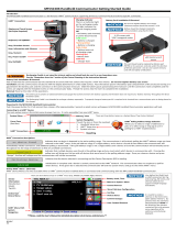
The DVC6200 housing is available in two different configurations, depending on the actuator mounting method.
Figure 2‐1 shows the available configurations.
Figure 2‐1. Housing Configurations
LINEAR, M8
ROTARY NAMUR, M6
SLOTS FOR
MOUNTING BOLTS
HOUSING FOR
LINEAR AND ROTARY ACTUATORS
HOUSING FOR
FISHER GX ACTUATORS
HOLE FOR
MOUNTING BOLT
W9704
W9703
INTEGRAL OUTPUT
PRESSURE PORT

Instruction Manual
D103409X012
Installation
December 2013
12
The feedback system for the DVC6200 digital valve controller utilizes a magnetic assembly for linkage‐less,
non‐contacting position measurement. In order to prevent inadvertent stem movement while the instrument is in
operation, magnetic tools (such as a magnetic‐tipped screwdriver) should not be used.
Note
The magnet assembly may be referred to as a magnetic array in user interface tools.
CAUTION
The magnet assembly material has been specifically chosen to provide a long‐term stable magnetic field.
However, as with any magnet, care must be taken when handling the magnet assembly. Another high powered magnet
placed in close proximity (less than 25 mm) can cause permanent damage. Potential sources of damaging equipment
include, but are not limited to: transformers, DC motors, stacking magnet assemblies.
CAUTION
General Guidelines for use of High Power Magnets with Positioners
Use of high power magnets in close proximity to any positioner which is operating a process should be avoided. Regardless
of the positioner model, high power magnets can affect the positioner’s ability to control the valve. Technicians should
avoid the use of high power magnets in close proximity with any positioner.
Use of Magnetic Tools with the DVC6200
D Magnetic Tip Screw Drivers – Magnetic tip screw drivers can be used to work on the DVC6200. However, they should
not be brought in close proximity to the magnet assembly (located at the back of the instrument) during process
operations.
D Calibrator Strap Magnets
– These are high power magnets used to hold 4-20 ma calibrators.
Normally, these calibrators would not be used while an instrument is controlling the process.
High power magnets should be kept at least 15 cm (6 inches) from the DVC6200.
Note
As a general rule, do not use less than 60% of the magnet assembly travel range for full travel measurement. Performance will
decrease as the assembly is increasingly subranged.
The linear magnet assemblies have a valid travel range indicated by arrows molded into the piece. This means that the hall sensor
(on the back of the DVC6200 housing) has to remain within this range throughout the entire valve travel. See figure 2‐2. The linear
magnet assemblies are symmetrical. Either end may be up.

Instruction Manual
D103409X012
Installation
December 2013
13
Figure 2‐2. Travel Range
INDEX MARK
VALID TRAVEL RANGE
50 mm (2 INCH) SHOWN
MAGNET ASSEMBLY
(ATTACHED TO VALVE STEM)
W9706
Note
Mounting the instrument vertically, with the vent at the bottom of the assembly, or horizontally, with the vent pointing down, is
recommended to allow drainage of moisture that may be introduced via the instrument air supply.
There are a variety of mounting brackets and kits that are used to mount the DVC6200 to different actuators.
Depending on the actuator, there will be differences in fasteners, brackets, and connecting linkages.
Each mounting kit will include one of the magnet assemblies illustrated in figure 2‐3.
Figure 2‐3. Magnet Assemblies
RSHAFT END
ASSEMBLY 90 DEG
AVAILABLE CONSTRUCTIONS:
SSTEM #1 ROLLER ASSEMBLY
RSHAFT #1 WINDOW ASSEMBLY
(FISHER 2052 SIZE 2 & 3, 1051/1052
SIZE 40‐70, 1061 SIZE 30‐100,
SLIDING‐STEM > 210 mm (8.25 INCHES)
RSHAFT #2 WINDOW ASSEMBLY
(2052 SIZE 1, 1051/1052 SIZE 20-33)
Y
B
AVAILABLE CONSTRUCTIONS:
SSTEM #7 ASSEMBLY (7 mm / 1/4 INCH)
SSTEM #19 ASSEMBLY (19 mm / 3/4 INCH)
SSTEM #25 ASSEMBLY (25 mm / 1 INCH)
AVAILABLE CONSTRUCTIONS:
SSTEM #38 ASSEMBLY (38 mm / 1‐1/2 INCH)
SSTEM #50 ASSEMBLY (50 mm / 2 INCH)
SSTEM #100 ASSEMBLY (100 mm / 4 INCH)
SSTEM #210 ASSEMBLY (210 mm / 8-1/4 INCH)
If ordered as part of a control valve assembly, the factory will mount the digital valve controller on the actuator and
calibrate the instrument. If purchased separately, you will need a mounting kit to mount the digital valve controller on
the actuator. Each mounting kit includes detailed information on mounting the digital valve controller to a specific
actuator. Refer to table 2‐1 for the more common Fisher actuator mounting instructions, available at www.fisher.com
or your Emerson Process Management sales office.

Instruction Manual
D103409X012
Installation
December 2013
14
For general mounting guidelines, refer to the DVC6200 Series quick start guide (D103556X012), available at
www.fisher.com or your Emerson Process Management sales office.
Table 2‐1. DVC6200 Mounting Instructions
Instructions for Mounting: Part Number
585C/585CR Size 25 Actuator with or without Handjack D103439X012
585C/585CR Size 50 Actuator with or without Handjack D103440X012
657 and 667 Size 30-60 Actuators D103441X012
657 and 667 Size 34-60 Actuators with Handwheel D103442X012
657 and 667 Size 70, 76, and 87 Actuators (up to 2 inch travel) D103443X012
657 and 667 Size 70, 76, and 87 Actuators (4 inch travel) D103444X012
657 and 667 Size 80 Actuators (up to 2 inch travel) D103445X012
657 and 667 Size 80 Actuators (4 inch travel) D103446X012
1051 Size 33 and 1052 Size 20 and 33 Actuators (Window Mount) D103447X012
1051 and 1052 Size 33 Actuators (End Mount) D103448X012
1051 and 1052 Size 40-70 Actuators (Window Mount) D103449X012
1051 and 1052 Size 40-70 Actuators (End Mount) D103450X012
1052 Size 20 Actuator (End Mount) D103451X012
1061 Size 30-68 Actuator (Window Mount) D103453X012
1061 Size 80-100 Actuator (Window Mount) D103452X012
2052 Size 1, 2, 3 Actuator (End Mount) D103454X012
2052 Size 1, 2, 3 Actuator with Spacer (Window Mount) D103455X012
Baumann Sliding‐Stem Actuators D103456X012
GX Control Valve and Actuator System D103457X012
IEC60534‐6‐1 (NAMUR) Sliding Stem Actuators D103458X012
IEC60534‐6‐2 (NAMUR) Rotary Actuators D103459X012
Mounting the DVC6205 Base Unit
For remote‐mounted digital valve controllers, the DVC6205 base unit ships separately from the control valve and does
not include tubing, fittings or wiring. See the instructions that come with the mounting kit for detailed information on
mounting the feedback unit to a specific actuator model.
Mount the DVC6205 base unit on a 50.8 mm (2 inch) pipestand or wall. The included bracket is used for either
mounting method.
Wall Mounting
Refer to figures 2‐4 and 2‐5. Drill two holes in the wall using the dimensions shown in figure 2‐4. Attach the mounting
bracket to the base unit using four spacers and 25.4 mm (1‐inch) 1/4‐20 hex head screws. Attach the base unit to the
wall using suitable screws or bolts.
Pipestand Mounting
Refer to figure 2‐6. Position a standoff on the back of the base unit. Using two 101.6 mm (4‐inch) 1/4‐20 hex head
screws loosely attach the base unit to the pipestand with the mounting bracket. Position the second standoff, then
using the remaining 101.6 mm (4‐inch) hex head screws, securely fasten the base unit to the pipe stand.

Instruction Manual
D103409X012
Installation
December 2013
15
Figure 2‐4. FIELDVUE DVC6205 Base Unit with Mounting Bracket (Rear View)
10C1796‐A
57
(2.25)
72
(2.82)
2 MOUNTING
HOLES
8.6 (0.34)
MM
(INCH)
Figure 2‐5. FIELDVUE DVC6205 Base Unit Wall Mounting
1‐INCH 1/4‐20
HEX HEAD
SCREW
SPACER
MOUNTING BRACKET
X0428

Instruction Manual
D103409X012
Installation
December 2013
16
Figure 2‐6. FIELDVUE DVC6205 Base Unit Pipestand Mounting
4‐INCH 1/4‐20
HEX HEAD SCREW
STANDOFF
MOUNTING BRACKET
X0437
Mounting the DVC6215 Feedback Unit
If ordered as part of a control valve assembly, the factory mounts the feedback unit on the actuator, makes pneumatic
connections to the actuator, sets up, and calibrates the instrument. If you purchased the feedback unit separately, you
will need a mounting kit to mount the feedback unit on the actuator. See the instructions that come with the
mounting kit for detailed information on mounting the feedback unit to a specific actuator model.
The DVC6215 housing is available in two different configurations, depending on the actuator mounting method.
Figure 2‐7 shows the available configurations. The feedback system for the DVC6215 feedback unit utilizes a magnetic
assembly for true linkage‐less, non‐contacting position measurement. In order to prevent inadvertent stem
movement while the instrument is in operation, magnetic tools (such as a magnetic‐tipped screwdriver) should not be
used.
Figure 2‐7. Feedback Unit Housing Configurations
LINEAR, M8
ROTARY NAMUR, M6
HOUSING FOR
LINEAR AND ROTARY ACTUATORS
HOUSING FOR
FISHER GX ACTUATORS
HOLES FOR
MOUNTING BOLT
X0125
X0124
INTEGRAL OUTPUT
PRESSURE PORT

Instruction Manual
D103409X012
Installation
December 2013
17
CAUTION
The magnet assembly material has been specifically chosen to provide a long‐term stable magnetic field.
However, as with any magnet, care must be taken when handling the magnet assembly. Another high powered magnet
placed in close proximity (less than 25 mm) can cause permanent damage. Potential sources of damaging equipment
include, but are not limited to: transformers, DC motors, stacking magnet assemblies.
CAUTION
General Guidelines for use of High Power Magnets with Positioners
Use of high power magnets in close proximity to any positioner which is operating a process should be avoided. Regardless
of the positioner model, high power magnets can affect the positioner’s ability to control the valve. Technicians should
avoid the use of high power magnets in close proximity with any positioner.
Use of Magnetic Tools with the DVC6215
D Magnetic Tip Screw Drivers – Magnetic tip screw drivers can be used to work on the DVC6215. However, they should
not be brought in close proximity to the magnet assembly (located at the back of the instrument) during process
operations.
D Calibrator Strap Magnets
– These are high power magnets used to hold 4-20 ma calibrators.
Normally, these calibrators would not be used while an instrument is controlling the process.
High power magnets should be kept at least 15 cm (6 inches) from the DVC6215.
Note
As a general rule, do not use less than 60% of the magnet assembly travel range for full travel measurement. Performance will
decrease as the assembly is increasingly subranged.
The linear magnet assemblies have a valid travel range indicated by arrows molded into the piece. This means that the hall sensor
(on the back of the DVC6215 housing) has to remain within this range throughout the entire valve travel. See figure 2‐8. The linear
magnet assemblies are symmetrical. Either end may be up.
Figure 2‐8. Travel Range
INDEX MARK
VALID TRAVEL RANGE
50 mm (2 INCH)
SHOWN
MAGNET ASSEMBLY
(ATTACHED TO VALVE STEM)
X0126

Instruction Manual
D103409X012
Installation
December 2013
18
There are a variety of mounting brackets and kits that are used to mount the DVC6215 to different actuators.
Note
The DVC6215 feedback unit uses the same mountings as the DVC6200 digital valve controller.
However, despite subtle differences in fasteners, brackets, and connecting linkages, the procedures for mounting can
be categorized as follows:
D Sliding‐stem linear actuators
D Fisher rotary actuators
D GX actuator
D Quarter‐turn actuators
See figure 2‐3 for examples of the different travel feedback magnet assemblies.
Sliding‐Stem Linear Actuators up to 210 mm (8.25 Inches) of Travel
The DVC6215 feedback unit has linkage‐less, non‐contact feedback on sliding‐stem actuators with up to 210 mm
(8.25 inches) travel. Figure 2‐9 shows a typical mounting on a sliding stem actuator. For actuators with greater than
210 mm (8.25 inches) travel, see the guidelines on page 20.
1. Isolate the control valve from the process line pressure and release pressure from both sides of the valve body. Shut
off all pressure lines to the actuator, releasing all pressure from the actuator. Use lock‐out procedures to be sure
that the above measures stay in effect while you work on the equipment.
2. Attach the mounting bracket to the actuator.
Figure 2‐9. Mounting Parts for Sliding‐Stem Actuator with up to 210 mm (8.25 Inches) Travel
X0127
3. Loosely attach the feedback pieces and magnet assembly to the valve stem connector. Do not tighten the fasteners
because fine adjustment is required.

Instruction Manual
D103409X012
Installation
December 2013
19
CAUTION
Do not install a magnet assembly that is shorter than the physical travel of the actuator. Loss of control will result from the
magnet assembly moving outside the range of the index mark in the feedback slot of the DVC6215 housing.
4. Using the alignment template (supplied with the mounting kit), position the magnet assembly inside the retaining
slot.
5. Align the magnet assembly as follows:
For air‐to‐open actuators (e.g. Fisher 667) vertically align the magnet assembly so that the center line of the alignment
template is lined up as close as possible with the upper
extreme of the valid travel range on the magnet assembly. The
magnet assembly should be positioned so that the index mark in the feedback slot of the DVC6215 housing is within
the valid range on the magnet assembly throughout the range of travel. See figure 2‐10.
For air‐to‐close actuators (e.g. Fisher 657) vertically align the magnet assembly so that the center line of the alignment
template is lined up as close as possible with the lower
extreme of the valid travel range on the magnet assembly. The
magnet assembly should be positioned so that the index mark in the feedback slot of the DVC6215 housing is within
the valid range on the magnet assembly throughout the range of travel. See figure 2‐11.
W9718
ALIGNMENT
TEMPLATE
INDEX
MARK
RETAINING
SLOT
Figure 2‐10. Air‐to‐Open Magnet Assembly
Alignment
Figure 2‐11. Air‐to‐Close Magnet Assembly
Alignment
ALIGNMENT
TEMPLATE
W9719
RETAINING
SLOT
INDEX
MARK
6. Tighten the fasteners and remove the alignment template.
Note
Use a flat end hex key to tighten the mounting assembly fasteners to a torque of 2.37 N•m (21 in•lbf) for 4 mm screws, and
5.08 N•m (45 in•lbf) for 5 mm screws. While tightening the fasteners using the hex key should be sufficient, blue (medium) thread
locker may be used for additional security.

Instruction Manual
D103409X012
Installation
December 2013
20
7. Mount the feedback unit to the mounting bracket, using the mounting bolts.
8. Check for clearance between the magnet assembly and the DVC6215 feedback slot.
Note
Ensure that there is clearance between the magnet assembly and the DVC6215 housing slot throughout the full range of travel.
Fisher Rotary Actuators and Sliding‐Stem Linear Actuators over 210 mm (8.25 Inches) Travel
The DVC6215 feedback unit uses a cam (designed for linear response) and roller as the feedback mechanism. See
figures 2‐12 and 2‐13.
Figure 2‐12. Mounting on Rotary Actuators
ROTARY MOUNTING
KIT (DVC6215 NOT
SHOWN)
W9708
Figure 2‐13. Mounting on Sliding‐Stem (Linear)
Actuators over 210 mm (8.25 Inches) Travel
LONG STROKE
MOUNTING
KIT (DVC6215
NOT SHOWN)
MOUNTING
ADAPTOR
W9709
Note
All cams supplied with FIELDVUE mounting kits are characterized to provide a linear response.
There are three different mounting adaptions, based on the actuator design (see figure 2‐14).
Fisher Rotary Actuators
Refer to the following guidelines when mounting on rotary actuators.
1. Isolate the control valve from the process line pressure and release pressure from both sides of the valve body. Shut
off all pressure lines to the pneumatic actuator, releasing all pressure from the actuator. Use lock‐out procedures to
be sure that the above measures stay in effect while working on the equipment.
/