Page is loading ...

Fisherr FIELDVUE™ DVC6000 SIS Digital Valve
Controllers for Safety Instrumented System (SIS)
Solutions Instruction Manual
(Supported)
Supported products may not be manufactured again in any Emerson Process Management location under any
conditions. Spare parts availability is 7 years of best effort. Technical support is available.
Post‐sale documents (such as instruction manuals and quick start guides) are available on the CD and FishWeb. Many
are also available at www.fisher.com
.
Instruction manuals for supported products may be updated, if required, to support products in the field.
Pre‐sale documents (such as bulletins) for supported products are included on FishWeb for internal use. They are not
included on the CD.
Supported Product
D103230X012
DVC6000 SIS Digital Valve Controllers
October 2013
Emerson Process Management
Marshalltown, Iowa 50158 USA
Sorocaba, 18087 Brazil
Chatham, Kent ME4 4QZ UK
Dubai, United Arab Emirates
Singapore 128461 Singapore
www.Fisher.com
The contents of this publication are presented for informational purposes only, and while every effort has been made to ensure their accuracy, they are not
to be construed as warranties or guarantees, express or implied, regarding the products or services described herein or their use or applicability. All sales are
governed by our terms and conditions, which are available upon request. We reserve the right to modify or improve the designs or specifications of such
products at any time without notice.
E 2013 Fisher Controls International LLC. All rights reserved.
Fisher and FIELDVUE are marks owned by one of the companies in the Emerson Process Management business unit of Emerson Electric Co. Emerson Process
Management, Emerson, and the Emerson logo are trademarks and service marks of Emerson Electric Co. All other marks are the property of their respective
owners.
Neither Emerson, Emerson Process Management, nor any of their affiliated entities assumes responsibility for the selection, use or maintenance
of any product. Responsibility for proper selection, use, and maintenance of any product remains solely with the purchaser and end user.


Introduction and Specifications
Installation
Basic Setup
Detailed Setup
Calibration
Viewing Device Variables and Diagnostics
Maintenance and Troubleshooting
Parts
Appendices
Principle of Operation
Loop Schematics/Nameplates
Glossary
Index
DVC6000 SIS
Instruction Manual
D103230X012
September 2013
Fisherr FIELDVUEtDVC6000 SIS
Digital Valve Controllers for Safety
Instrumented System
(SIS) Solutions
This manual applies to:
Device Type 03 03
Device Revision 1 2
Hardware Revision 1 1
Firmware Revision 3 − 6 7, 9, 10, 11
DD Revision 8 8
www.Fisher.com
1
2
3
4
5
6
7
8
A
B
Glossary
14
Index

DVC6000 SIS
i
i
Fast Key Sequence
Function/Variable
Fast-Key
Sequence
Coordinates
(1)
Function/Variable
Fast-Key
Sequence
Coordinates
(1)
A Minus B 3-5-3 4-G Drive Signal Alert Enable 1-2-3-1-2-1 9-D
Action on Failed Test 1-2-7-5 2-D Device Power Up 1-2-7-5 2-D
Actuator Style 1-2-6-4 2-E End Point Control Enable 1-2-2-2-2-1 9-C
Alert Conditions 2-1 2-F EPPC Saturation Time 1-2-2-2-2-4 9-C
Alert Record Full Enable 1-2-3-7-2 10-H EPPC Set Point 1-2-2-2-2-3 9-C
Alert Record Has Entries Alert
Enable
1-2-3-7-1 10-H Failure Group Enable 1-2-3-7-5-1 10-I
Analog Input 3-1 2-G Firmware Revision 3-7-6 2-H
Analog Input Calibration 1-3-2-3 4-E Flash ROM Shutdown 1-2-3-1-3-5 12-C
Analog Input Range Hi 1-2-5-3-1 6-H Hardware Revision 3-7-7 2-H
Analog Input Range Lo 1-2-5-3-2 6-H
HART Tag
1-2-5-1-1 6-F
Analog Input Units 1-2-5-2-3 6-G 3-7-1 2-H
Assembly Specification Sheet 1-2-6-7 2-E HART Universal Revision 3-7-9 2-H
Auto Test Interval 1-2-7-3 2-D Input Characterization 1-2-2-3 4-C
Auto Travel Calibration 1-3-1-1 4-D
Instrument Date and Time
1-2-4-1-2 8-G
Autocalibration in Progress Enable 1-2-4-2-2 8-H 1-2-5-8 4-G
Auxiliary Input
3-6-1 4-H Instrument Level 3-7-8 2-H
1-2-3-3-1-2 12-D Instrument Mode Hot Key-1 1-A
Auxiliary Terminal Alert Enable 1-2-3-3-1-1 12-D Instrument Mode 1-2-1-1 4-B
Auxiliary Terminal Action
1-2-3-3-1-3 12-D Instrument Serial Number 1-2-5-1-6 6-G
1-2-5-7 4-F Instrument Time Invalid Enable 1-2-4-1-1 8-G
Burst Command 1-2-1-4-3 5-B
Integral Dead Zone
1-2-4-4-4 8-I
Burst Enable 1-2-1-4-1 5-B 1-2-2-1-2-1 8-B
Calibration in Progress Enable 1-2-4-2-1 8-H
Integral Limit
1-2-4-4-3 8-I
Change Burst Command 1-2-1-4-4 5−B 1-2-2-1-2-2 8-B
Change Burst Enable 1-2-1-4-2 5−B Integrator Saturated Hi Enable 1-2-4-4-1 8-I
Clear ALL Records 1-2-3-7-4 10-H Integrator Saturated Lo Enable 1-2-4-4-2 8-I
Cmd 3 Configured Pressure 1-2-1-4-5 6−B Last AutoCal Status 1-2-5-9-1 6-H
Control Mode
Hot Key-2 1-A Last Calibration Type 1-2-5-9-2 6-H
1-2-1-2 4-B
Low Power Write Fail Enable
(FW 9 and 10)
1-2-3-1-3-2 12-B
Critical NVM Shutdown 1-2-3-1-3-4 12-C Manual Travel Calibration 1-3-1-2 4-E
Custom Characterization Table 1-2-2-4 4-C
Manufacturer
3-7-3 2-H
Cycle Counter
1-2-3-5-1-2 12-G 1-2-6-1 2-D
3-6-5 4-H
Maximum Recorded Temperature
2-3-1 4-F
Cycle Count Alert Enable 1-2-3-5-1-1 12-G 3-6-3 4-H
Cycle Count Alert Point 1-2-3-5-1-3 12-G
Minimum Recorded Temperature
2-3-2 4−F
Date 1-2-5-1-4 6-F 3-6-4 4-H
Dead Band (Cycle Count / Travel
Accum)
1-2-3-5-2-1 12-H Maximum Supply Pressure 1-2-5-6 4-F
Descriptor 1-2-5-1-3 6-F Message 1-2-5-1-2 6-F
Device Description Information 3-8 2-G Miscellaneous Group Enable 1-2-3-7-5-3 11-I
Device ID 3-7-2 2-H Model 3-7-4 2-H
Device Revision 3-7-5 2-H Multi-Drop Enable 1-2-4-3-2 8-H
Diagnostic Data Available Enable 1-2-4-2-4 8-H No Free Time Shutdown 1-2-3-1-3-6 12-C
Diagnostic in Progress Enable 1-2-4-2-3 8-H Non-Critical NVM Alert Enable 1-2-3-1-3-3 12-C
Drive Current Shutdown 1-2-3-1-1 8-D
Number of Power Ups
2-3-4 3-F
Drive Signal
3-4 2-G 3-6-9 4-I
1-2-3-1-2-2 9-D Offline/Failed Alert Enable 1-2-3-1-3-1 12-B
1. Coordinates are to help locate the menu item on the menu tree on the following pages.

DVC6000 SIS
ii
ii
Fast Key Sequence
Function/Variable
Fast-Key
Sequence
Coordinates
(1)
Function/Variable
Fast-Key
Sequence
Coordinates
(1)
Partial Stroke Test 2-5 2-F
Travel
3-3 2-G
Partial Stroke Test Enable 1-2-7-1 2-C 1-2-3-4-1 9-E
Partial Stroke Test Pressure Limit 1-2-3-6-1 10-G
Travel/Pressure Cutoff Hi
1-2-3-4-7-3 12-F
Partial Stroke Test Start Point 1-2-2-2-2-2 9-C 1-2-2-2-1-1 10-B
Performance Tuner
1-1-2 3-B
Travel/Pressure Cutoff Lo
1-2-3-4-7-4 12-G
1-2-2-1-1-5 8-B 1-2-2-2-1-2 10-B
Polling Address 1-2-5-1-7 6-G
Travel Accumulator
3-6-6 4-H
Power Starvation Alert Enable
(FW 7 only)
1-2-3-1-3-2 12-B 1-2-3-5-3-2 12-I
Pressure A 3-5-1 4-G Travel Accumulator Alert Enable 1-2-3-5-3-1 12-H
Pressure B 3-5-2 4-G Travel Accumulator Alert Point 1-2-3-5-3-3 12-I
Pressure Deviation Alert Enable 1-2-3-6-2 10-G Travel Alert Dead Band 1-2-3-4-3 9-F
Pressure Deviation Alert Point 1-2-3-6-3 10-G Travel Alert Hi Enable 1-2-3-4-6-1 10-F
Pressure Deviation Time 1-2-3-6-4 10-G Travel Alert Hi Hi Enable 1-2-3-4-5-1 12-E
Pressure Integral Control Enable 1-2-2-1-3-2 8-C Travel Alert Hi Hi Point 1-2-3-4-5-3 12-F
Pressure Integral Gain 1-2-2-1-3-3 8-C Travel Alert Hi Point 1-2-3-4-6-3 10-F
Pressure Sensor Shutdown 1-2-3-2-3 12-C Travel Alert Lo Enable 1-2-3-4-6-2 10-F
Pressure Sensors—Calibration 1-3-2-1 4-E Travel Alert Lo Lo Enable 1-2-3-4-5-2 12-F
Pressure Tuning Set 1-2-2-1-3-1 8-C Travel Alert Lo Lo Point 1-2-3-4-5-4 12-F
Pressure Units 1-2-5-2-1 6-G Travel Alert Lo Point 1-2-3-4-6-4 12-F
Protection
Hot Key-3 1-A Travel Deviation Alert Enable 1-2-3-4-4-1 10-E
1-2-1-5 4-B Travel Deviation Alert Point 1-2-3-4-4-2 10-E
PST Calibration 1−3−5 2-F Travel Deviation Time 1-2-3-4-4-3 10-E
Raw Travel Input 3-6-7 4-H Travel Integral Control Enable 1-2-2-1-1-2 8-A
Reference Voltage Shutdown 1-2-3-1-3-7 12-C Travel Integral Gain 1-2-2-1-1-3 8-A
Relay Adjust 1-3-3 2-E Travel Limit/Cutoff Hi Alert Enable 1-2-3-4-7-1 12-F
Relay Type 1-2-5-4 4-F Travel Limit/Cutoff Lo Alert Enable 1-2-3-4-7-2 12-F
Restart Control Mode 1-2-1-3 4-B Travel Sensor Adjust 1-3-2-2 4-E
Restore Factory Settings 1-3-4 2-E Travel Sensor Motion 1-2-6-5 2-E
Set Point 1−2−3−4−2 9-E Travel Sensor Shutdown 1-2-3-2-1 12-C
Set Point Rate Close 1-2-2-5-2 5-C
Travel Set Point
1-2-3-4-2 9-E
Set Point Rate Open 1-2-2-5-1 5-C 3-2 2-G
Setup Wizard 1-1-1 2-B Travel Tuning Set 1-2-2-1-1-1 8-A
Stabilize/Optimize
Hot Key-4 1-A Valve Group Enable 1-2-3-7-5-2 11-I
1-2-2-1-1-4 8-A
Valve Serial Number
1-2-5-1-5 6-F
Status 2-2 2-F 1-2-6-2 2-D
Stroke Valve 2-4 2-F Valve Style 1-2-6-3 2-D
Supply Pressure
3-5-4 4-H View Alert Records 1-2-3-7-3 10-H
1-2-3-3-2-2 12-E View/Edit Feedback Connection 1-2-6-6 2-E
Supply Pressure Lo Alert Enable 1-2-3-3-2-1 12-E View/Edit Lag Time 1-2-2-5-3 5-D
Supply Pressure Lo Alert Point 1-2-3-3-2-3 12-E
View/Edit Partial Stroke Test
Variables
1-2-7-2 2-C
Temperature 3-6-2 4-H
View Number of Days Powered Up
2-3-3 3-F
Temperature Sensor Shutdown 1-2-3-2-2 12-C 3-6-8 4-H
Temperature Units 1-2-5-2-2 6-G Zero Power Condition 1-2-5-5 4-F
1. Coordinates are to help locate the menu item on the menu tree on the following pages.

DVC6000 SIS
iii
iii
Response Control
1 Tuning
2 Travel/Pressure Control
3 Input Characterization
4 Custom Characterization Table
5 Dynamic Response
Hot Key
1 Instrument Mode
2 Control Mode
3 Protection
4 Stabilize/Optimize
1-1
1
1
1
1-2-1
1-2
1-2-4
1-2-1-4
1-2-5
1-2-6
1-3
1-3-1
1-3-2
2
3-5
3-6
1
2345
6
2
2-3
1-2-7
1-2-3
3-7
3
1-2-2
1-2-5-2
1-2-5-3
1-2-2-1
1-2-2-2
1-2-2-5
1-2-5-9
1-2-5-1
Guided Setup
1 Setup Wizard
2 Performance Tuner
Detailed Setup
1 Mode and Protection
2 Response Control
3 Alert Setup
4 Status
5 Instrument
6 Valve and Actuator
7 SIS/Partial Stroke
Online
1 Configure
2 Service Tools
3 Overview
Configure
1 Guided Setup
2 Detailed Setup
3 Calibrate
HART Application
1 Offline
2 Online
3 Utility
4 HART Diagnostics
Calibrate
1 Travel Calibration
2 Sensor Calibration
3 Relay Adjust
4 Restore Factory
4 Settings
5 PST Calibration
SIS/Partial Stroke
1 PST Enable
2 View/Edit PST Variables
3 View/Edit Auto Test Interval
4 Device Power Up
5 Action on Failed Test
Burst Mode
1 Burst Enable
2 Change Burst Enable
3 Burst Command
4 Change Burst Command
5 Cmd 3 Configured Pressure
Mode and Protection
1 Instrument Mode
2 Control Mode
3 Restart Control Mode
4 Burst Mode
5 Protection
Device Information
1 HART Tag
2 Device ID
3 Manufacturer
4 Model
5 Device Revision
6 Firmware Revision
7 Hardware Revision
8 Instrument Level
9 HART Universal Revision
Variables
1 Auxiliary Input
2 Temperature
3 Maximum Recorded Temperature
4 Minimum Recorded Temperature
5 Cycle Counter
6 Travel Accumulator
7 Raw Travel Input
8 View Number of Days Powered Up
9 Number of Power Ups
Pressure
1 Pressure A
2 Pressure B
3 A Minus B
4 Supply
Service Tools
1 Alert Conditions
2 Status
3 Device Record
4 Stroke Valve
5 Partial Stroke Test
Overview
1 Analog In
2 Setpoint
3 Travel
4 Drive Signal
5 Pressure
6 Variables
7 Device Information
8 DD Information
Device Record
1 Maximum Recorded Temperature
2 Minimum Recorderd Temperature
3 View Number of Days Powered Up
4 Number of Power Ups
Travel Calibration
1 Auto Calibration
2 Manual Calibration
Sensor Calibration
1 Pressure Sensors
2 Travel Sensor
3 Analog In
Alert Setup
1 Electronics Alerts
2 Sensor Alerts
3 Environment Alerts
4 Travel Alerts
5 Travel History Alerts
6 SIS Alerts
6 Alert Record
Valve and Actuator
1 Manufacturer
2 Valve Serial Number
3 Valve Style
4 Actuator Style
5 Travel Sensor Motion
6 View/ Edit Feedback Connection
7 Assembly Specification Sheet
Tuning
1 Travel Tuning
2 Integral Settings
3 Pressure Tuning
Travel/Pressure Control
1 Travel/Pressure Cutoffs
2 End Point Pressure Control
Dynamic Response
1 SP Rate Open
2 SP Rate Close
3 View/Edit Lag Time
Instrument
1 General
2 Units
3 Analog Input Range
4 Relay Type
5 Zero Power Condition
6 Maximum Supply Pressure
7 Auxiliary Terminal Action
8 Instrument Date and Time
9 Calib Status and Type
Status
1 Instrument Time
2 Calibrations and Diagnostics
3 Operational
4 Integrator Saturation
Units
1 Pressure Units
2 Temperature Units
3 Analog In Units
Analog Input Range
1 Input Range Hi
2 Input Range Lo
Calib Status and Type
1 Last AutoCal Status
2 Last Calibration Type
General
1 HART Tag
2 Message
3 Descriptor
4 Date
5 Valve Serial Number
6 Instrument Serial Number
7 Polling Address
Notes:
1‐1‐1 indicates fast‐key sequence to reach menu
This menu is available by pressing the left
arrow key from the previous menu.
Method to change PST Enable (1‐2‐7‐1)
Field Communicator Menu Tree for
DVC6000 SIS Digital Valve Controllers

DVC6000 SIS
iv
iv
78 910 11
A
B
C
D
E
F
G
H
I
12
Electronics Alerts
1 Drive Current Shutdown
2 Drive Signal Alert
3 Processor Impaired Alerts
Travel Tuning
1 Travel Tuning Set
2 Integral Enable
3 Integral Gain
4 Stabilize / Optimize
5 Performance Tuner
Integral Settings
1 Integral Dead Zone
2 Integral Limit
Pressure Tuning
1 Pressure Tuning Set
2 Integral Enable
3 Integral Gain
Travel/Pressure Cutoffs
1 Cutoff Hi
2 Cutoff Lo
3 Change Cutoffs
Drive Signal Alert
1 Drive Signal Alert Enable
2 Drive Signal
Processor Impaired Alerts
1 Offline/Failed Alert Enable
2 Low Power Write Fail Enable
3 Non-Critical NVM Alert Enable
4 Critical NVM Shutdown
5 Flash ROM Shutdown
6 No Free Time Shutdown
7 Reference Voltage Shutdown
Sensor Alerts
1 Travel Sensor Shutdown
2 Temp Sensor Shutdown
3 Pressure Sensor Shutdown
Environment Alerts
1 Auxiliary Terminal Alert
2 Supply Pressure Lo Alert
3 Loop Current Validation
Enable
Travel Limit Alerts
1 Travel Alert Hi Hi Enable
2 Travel Alert Lo Lo Enable
3 Travel Alert Hi Hi Point
4 Travel Alert Lo Lo Point
Travel Alerts
1 Travel
2 Set Point
3 Travel Alert DB
4 Travel Deviation Alert
5 Travel Limit Alerts
6 Travel Limit Hi/Lo Alerts
7 Travel Limit/Cutoff Alerts
Travel History Alerts
1 Cycle Counter
2 Cycle Count/Travel Accumulator Deadband
3 Travel Accumulator
Travel Limit Hi/Lo Alerts
1 Travel Alert Hi Enable
2 Travel Alert Lo Enable
3 Travel Alert Hi Point
4 Travel Alert Lo Point
Travel Limit/Cutoff Alerts
1 Travel Limit/Cutoff Hi Enable
2 Tvl Limit/Cutoff Lo Enable
3 Cutoff Hi
4 Cutoff Lo
5 Change Cutoffs
Integrator Saturation
1 Integrator Sat Hi Enable
2 Integrator Sat Lo Enable
3 Integral Limit
4 Integral Dead Zone
Travel Deviation Alert
1 Travel Deviation Alert Enable
2 Travel Deviation Alert Point
3 Travel Deviation Time
Travel Accumulator
1 Travel Accumulator Alert Enable
2 Travel Accumulator
3 Travel Accumulator Alert Point
Cycle Counter
1 Cycle Count Alert Enable
2 Cycle Counter
3 Cycle Count Alert Point
Instrument Time
1 Inst Time Invalid Enable
2 Instrument Date and Time
Calibrations and Diagnostics
1 Calibration in Progress Enable
2 Autocal in Progress Enable
3 Diagnostic in Progress Enable
4 Diagnostic Data Avail Enable
Operational
1 Pressure Control Active Enable
2 Multi-Drop Enable
1-2-2-1-1
1-2-2-2-1
1-2-3-1
1-2-3-1-2
End Point Pressure Control
1 End Pt Control Enab
2 PST Start Pt
3 EPPC Set Point
4 EPPC Saturation Time
1-2-2-2-2
SIS Alerts
1 PST Pressure Limit
2 Pressure Deviation Alert Enable
3 Pressure Deviation Alert Point
4 Pressure Deviation Time
Supply Pressure Lo Alert
1 Supply Pressure Lo Alert Enable
2 Supply
3 Supply Pressure Lo Alert Point
Auxiliary Terminal Alert
1 Auxiliary Terminal Alert Enable
2 Auxiliary Input
3 Auxiliary Terminal Action
Alert Record
1 Alert Record Has Entries Enable
2 Alert Record Full Enable
3 View Alert Records
4 Clear ALL Record
5 Alert Groups
Alert Groups
1 Failure Group Enable
2 Valve Group Enable
3 Miscellaneous Group Enable
Cycle Count/Travel
Accumulator Deadband
1 Deadband
1-2-3-6
1-2-3-2
1-2-3-3
1-2-3-5
1-2-3-7
1-2-2-1-2
1-2-2-1-3
1-2-3-5-1
1-2-3-7−5
1-2-4-2
1-2-4-3
1-2-4-4
1-2-4-1
1-2-3-5-3
1-2-3-5-2
1-2-3-1-3
1-2-3-4
1-2-3-3-1
1-2-3-3-2
1-2-3-4-4
1-2-3-4-5
1-2-3-4-6
1-2-3-4-7

DVC6000 SIS
v
v
FIELDVUE DVC6000 SIS Digital Valve Controller
THE FIELDVUE DVC6000 SIS DIGITAL VALVE CONTROLLER IS A CORE COMPONENT OF THE PLANTWEBt
DIGITAL PLANT ARCHITECTURE. THE DIGITAL VALVE CONTROLLER POWERS PLANTWEB BY CAPTURING
AND DELIVERING VALVE DIAGNOSTIC DATA. COUPLED WITH VALVELINK
t
SOFTWARE, THE DVC6000 SIS
PROVIDES USERS WITH AN ACCURATE PICTURE OF VALVE PERFORMANCE, INCLUDING ACTUAL STEM
POSITION, INSTRUMENT INPUT SIGNAL AND PNEUMATIC PRESSURE TO THE ACTUATOR. USING THIS
INFORMATION, THE DIGITAL VALVE CONTROLLER DIAGNOSES NOT ONLY ITSELF, BUT ALSO THE VALVE
AND ACTUATOR TO WHICH IT IS MOUNTED.

Introduction and Specifications
September 2013
1-1
1-1
Section 1 Introduction and Specifications
Scope of Manual 1-2........................................................
Conventions Used in this Manual 1-2.....................................
Description 1-2..............................................................
Specifications 1-3...........................................................
Related Documents 1-7.....................................................
Educational Services 1-7...................................................
1

DVC6000 SIS
September 2013
1-2
Table 1-1. FIELDVUE DVC6000 SIS Capabilities
Auto Calibration
Custom Characterization
Alerts
Step Response, Drive Signal Test & Dynamic Error Band
Advanced Diagnostics (Valve Signature)
Performance Tuner
Performance Diagnostics
(1)
Solenoid Valve Health Monitoring
(1)
Partial Stroke Testing
1. Available in Firmware Revision 7 and higher.
Scope of Manual
This instruction manual includes specifications and
installation, operation, and maintenance information
for FIELDVUE DVC6000 SIS digital valve controllers
for Safety Instrumented System (SIS) Solutions,
device revision 1, firmware revision 3−6 or device
revision 2, firmware 7, 9, 10, and 11.
This instruction manual describes using the 475 Field
Communicator with device description revision 8, used
with DVC6000 SIS device revision 2, firmware revision
7, 9, 10, or 11 to setup and calibrate the instrument.
You can also use Fisher ValveLink software version
7.3 or higher to setup, calibrate, and diagnose the
valve and instrument. For information on using
ValveLink software with the instrument, refer to the
ValveLink software help or documentation.
Do not install, operate, or maintain a DVC6000 SIS
digital valve controller without being fully trained and
qualified in valve, actuator, and accessory installation,
operation, and maintenance. To avoid personal
injury or property damage, it is important to
carefully read, understand, and follow all of the
contents of this manual, including all safety
cautions and warnings. If you have any questions
about these instructions, contact your Emerson
Process Management sales office before proceeding
Conventions Used in this Manual
Procedures that require the use of a Field
Communicator have the Field Communicator symbol
in the heading.
Procedures that are accessible with the Hot Key
on the Field Communicator will also have the Hot Key
symbol in the heading.
Some of the procedures also contain the sequence of
numeric keys required to display the desired Field
Communicator menu. For example, to access Device
Setup, from the Online menu, press 2 (selects
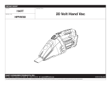
Figure 1-1. FIELDVUE DVC6030 SIS Digital Valve
Controller Mounted on a Quarter-Turn Actuator
W8308-3 SIS
Configure) followed by a 1 (selects Guided Setup)
followed by a second 1 (selects Setup Wizard). The
key sequence in the procedure heading is shown as
(2-1-1). The path required to accomplish various
tasks, the sequence of steps through the Field
Communicator menus, is also presented in textual
format. An overview of the Field Communicator menu
structures are shown at the beginning of this manual.
Description
DVC6000 SIS digital valve controllers (figure 1-1) are
communicating, microprocessor-based
current-to-pneumatic instruments. The DVC6000 SIS
digital valve controller for Safety Instrumented System
(SIS) Solutions monitors the health of final control
elements and solenoid valves; the primary function of
the DVC6000 SIS is to actuate its pneumatic outputs
in response to a demand signal from a logic solver,
which should move the valve to the configured safe
state.
Using HART communications protocol the digital
valve controller allows easy access to information
critical to process operation. You can gain information
from the principal component of the process, the
control valve itself, using the Field Communicator at
the valve or at a field junction box, or by using a
personal computer or operator’s console within the
control room.
DVC6000 SIS instruments permits partial stroking of
the valve to minimize the chance of valve failure upon
a safety demand and, consequently, the possibility of
catastrophic situations. A partial stroke test verifies
valve movement with a small ramp to the input. This
ramp is small enough not to disrupt production, but is
large enough to confirm that the valve is working.
DVC6000 SIS instruments also provide state-of-the-art
1

Introduction and Specifications
September 2013
1-3
testing methods, which reduce testing and
maintenance time, improve system performance, and
provide diagnostic capabilities.
Using a personal computer and ValveLink software,
AMS Suite: Intelligent Device Manager, or a Field
Communicator, you can perform several operations
with the DVC6000 SIS digital valve controller. You can
obtain general information concerning software
revision level, messages, tag, descriptor, and date.
Diagnostic information is available to aid you when
troubleshooting. Input and output configuration
parameters can be set, and the digital valve controller
can be calibrated. Refer to table 1-1 for details on the
capabilities of the DVC6000 SIS.
Using the HART protocol, information from the field
can be integrated into control systems or be received
on a single loop basis.
Specifications
WARNING
Refer to table 1-2 for application
specifications. Incorrect configuration
of a positioning instrument could
result in the malfunction of the
product, property damage or personal
injury.
Specifications for DVC6000 SIS digital valve
controllers are shown in table 1-2. Specifications for
the Field Communicator can be found in the product
manual for the Field Communicator.
1

DVC6000 SIS
September 2013
1-4
Table 1-2. Specifications
Available Configurations
Valve-Mounted Instruments
DVC6010 SIS: Sliding-stem applications
DVC6020 SIS: Rotary and long-stroke sliding-stem
applications [over 102 mm (4 inch) travel]
DVC6030 SIS: Quarter-turn rotary applications
All units can be used in either 4-wire or 2-wire
system installations.
DVC6000 SIS digital valve controllers must have
the Safety Instrumented System Application (SIS)
option
Remote-Mounted Instrument
(1)
DVC6005 SIS: Base unit for 2 inch pipestand or
wall mounting
DVC6015: Feedback unit for sliding-stem
applications
DVC6025: Feedback unit for rotary or long-stroke
sliding-stem applications
DVC6035: Feedback unit for quarter-turn rotary
applications
DVC6000 SIS digital valve controllers can be
mounted on Fisher and other manufacturers rotary
and sliding-stem actuators
Input Signal
Point-to-Point:
Analog Input Signal: 4-20 mA DC, nominal
Minimum voltage available at instrument terminals
must be 10.5 VDC for analog control, 11 VDC for
HART communication
Minimum Control Current: 4.0 mA
Minimum Current w/o Microprocessor Restart:
3.5 mA
Maximum Voltage: 30 VDC
Overcurrent Protection: Input circuitry limits current
to prevent internal damage
Reverse Polarity Protection: No damage occurs
from reversal of loop current
Multi-drop:
Instrument Power: 11-30 VDC at approximately
8 mA
Reverse Polarity Protection: No damage occurs
from reversal of loop current
Output Signal
Pneumatic signal as required by the actuator, up to
full supply pressure.
Minimum Span: 0.4 bar (6 psig)
Maximum Span: 9.5 bar (140 psig)
Action: Double, Single direct, and Single reverse
Supply Pressure
(2)
Recommended: 1.7 bar (25 psi) or 0.3 bar (5 psi)
plus the maximum actuator requirements,
whichever is higher
Maximum: 10 bar (145 psig) or maximum pressure
rating of the actuator, whichever is lower
Supply Medium
Air: Supply pressure must be clean, dry air that
meets the requirements of ISA Standard 7.0.01.
Natural Gas: Natural gas must be clean, dry,
oil-free, and noncorrosive. H
2
S content should not
exceed 20 ppm.
A maximum 40 micrometer particle size in the air
system is acceptable. Further filtration down to 5
micrometer particle size is recommended. Lubricant
content is not to exceed 1 ppm weight (w/w) or
volume (v/v) basis. Condensation in the air supply
should be minimized
Steady-State Air Consumption
(3,4)
Low Bleed Relay
At 1.4 bar (20 psig) supply pressure: Average value
0.056 normal m
3
/hr (2.1 scfh)
At 5.5 bar (80 psig) supply pressure: Average value
0.184 normal m
3
/hr (6.9 scfh)
The low bleed relay is the standard relay for
DVC6000 SIS digital valve controllers, used for
On/Off applications. Performance may be affected
in throttling applications.
Standard Relay:
At 1.4 bar (20 psig) supply pressure:
Less than 0.38 normal m
3
/hr (14 scfh)
At 5.5 bar (80 psig) supply pressure:
Less than 1.3 normal m
3
/hr (49 scfh)
Maximum Output Capacity
(3,4)
At 1.4 bar (20 psig) supply pressure:
10.0 normal m
3
/hr (375 scfh)
At 5.5 bar (80 psig) supply pressure:
29.5 normal m
3
/hr (1100 scfh)
Independent Linearity
(5)
±0.50% of output span
−continued−
1

Introduction and Specifications
September 2013
1-5
Table 1-2. Specifications (continued)
Electromagnetic Interference (EMI)
Meets EN 61326-1 (First Edition)
Immunity—Industrial locations per Table 2 of
the EN 61326-1 standard. Performance is
shown in table 1-3 below.
Emissions—Class A
ISM equipment rating: Group 1, Class A
Lightning and Surge Protection—The degree of
immunity to lightning is specified as Surge immunity
in table 1-3. For additional surge protection
commercially available transient protection devices
can be used.
Vibration Testing Method
Tested per ISA-S75.13 Section 5.3.5. A resonant
frequency search is performed on all three axes.
The instrument is subjected to the ISA specified 1/2
hour endurance test at each major resonance, plus
an additional two million cycles.
Input Impedance (Point-to-Point only)
The input impedance of the DVC6000 SIS active
electronic circuit is not purely resistive. For
comparison to resistive load specifications, an
equivalent impedance of 550 ohms may be used.
This value corresponds to 11 V @ 20 mA.
Operating Ambient Temperature Limits
(2,6)
−40 to 85C (−40 to 185F) for most approved
valve-mounted instruments
−60 to 125C (−76 to 257F) for remote-mounted
feedback unit
−52 to 85C (−62 to 185F) for valve-mounted
instruments utilizing the Extreme Temperature
option (fluorosilicone elastomers)
Humidity Limits
0 to 100% condensing relative humidity with
minimal zero or span shifts
Electrical Classification
Hazardous Area
CSA—Intrinsically Safe, Explosion-proof,
Division 2, Dust Ignition-proof
FM—Intrinsically Safe, Explosion-proof,
Non-incendive, Dust Ignition-proof
ATEX—Intrinsically Safe, Flameproof, Type n
IECEx—Intrinsically Safe, Flameproof, Type n
Electrical Housing
CSA—Type 4, IP66
FM—Type 4, IP66
ATEX—IP66
IECEx—IP66
Refer to tables 1-4, 1-5, 1-6 and 1-7, Hazardous
Area Classifications and Special Instructions for
“Safe Use” and Installation in Hazardous Locations
in Section 2, and Appendix B for specific approval
information.
Pollution Degree 2, Overvoltage Category III per
ANSI/ISA-82.02.01 (IEC 61010-1 Mod).
Auxiliary Terminal Contact: Nominal Electrical
Rating 5 V, <1 mA; It is recommended that the
switch be sealed or have gold plated contacts to
avoid corrosion.
For proper operation of the auxiliary input terminal
capacitance should not exceed 18000pF.
Other Classifications/Certifications
Gas Certified, Single Seal Device— CSA, FM,
ATEX, and IECEx
FSETAN—Federal Service of Technological,
Ecological and Nuclear Inspectorate (Russia)
GOST-R—Russian GOST-R
INMETRO— National Institute of Metrology,
Quality, and Technology (Brazil)
KGS—Korea Gas Safety Corporation (South Korea)
KISCO—Korea Industrial Safety Corporation (South
Korea)
NEPSI— National Supervision and Inspection
Centre for Explosion Protection and Safety of
Instrumentation (China)
PESO CCOE— Petroleum and Explosives Safety
Organisation − Chief Controller of Explosives (India)
TIIS— Technology Institution of Industrial Safety
(Japan)
Contact your Emerson Process Management sales
office for classification/certification specific
information
IEC 61010 Compliance Requirements
(Valve-Mounted Instruments only)
Power Source: The loop current must be derived
from a Separated Extra-Low Voltage (SELV) power
source.
Environmental Conditions: Installation Category I
−continued−
1

DVC6000 SIS
September 2013
1-6
Table 1-2. Specifications (continued)
Connections
Supply Pressure: 1/4 NPT internal and integral
pad for mounting 67CFR regulator
Output Pressure: 1/4 NPT internal
Tubing: 3/8-inch, recommended
Vent: 3/8 NPT internal
Electrical: 1/2 NPT internal conduit connection,
M20 adapter optional
Stem/Shaft Travel
Linear Actuators with rated travel between
6.35 mm (0.25 inch) and 606 mm (23.375 inches)
Rotary Actuators with rated travel between 50
degrees and 180 degrees.
Mounting
Designed for direct actuator mounting or remote
pipestand or wall mounting. Mounting the
instrument vertically, with the vent at the bottom of
the assembly, or horizontally, with the vent pointing
down, is recommended to allow drainage of
moisture that may be introduced via the instrument
air supply.
Weight
Valve-Mounted Instruments
Aluminum: 3.5 kg (7.7 lbs)
Stainless Steel: 7.7 kg (17 lbs)
Remote-Mounted Instruments
DVC6005 SIS Base Unit: 4.1 kg (9 lbs)
DVC6015 Feedback Unit: 1.3 kg (2.9 lbs)
DVC6025 Feedback Unit: 1.4 kg (3.1 lbs)
DVC6035 Feedback Unit: 0.9 kg (2.0 lbs)
Construction Materials
Housing, module base and terminal box:
A03600 low copper aluminum alloy (standard)
CF8M (cast 316 stainless steel) (optional for
valve-mounted instruments only)
Cover: Thermoplastic polyester
Elastomers
Standard: Nitrile
Optional: Fluorosilicone
Options
Supply and output pressure gauges or Tire
valves, Integral mounted filter regulator,
Stainless steel housing, module base, and
terminal box, Extreme Temperature, Beacon
Indicator, LCP100 local control panel Natural
Gas Certified, Single Seal Device, Feedback
Assembly PTFE Sleeve Protective Kit for aluminum
units in saltwater or particulate environments
Declaration of SEP
Fisher Controls International LLC declares this
product to be in compliance with Article 3 paragraph
3 of the Pressure Equipment Directive (PED) 97 /
23 / EC. It was designed and manufactured in
accordance with Sound Engineering Practice (SEP)
and cannot bear the CE marking related to PED
compliance.
However, the product may bear the CE marking to
indicate compliance with other applicable European
Community Directives.
NOTE: Specialized instrument terms are defined in ANSI/ISA Standard 51.1 − Process Instrument Terminology.
1. 3-conductor shielded cable, 22 AWG minimum wire size, is required for connection between base unit and feedback unit. Pneumatic tubing between base unit output connection and actuator
has been tested to 91 meters (300 feet). At 15 meters (50 feet) there was no performance degradation. At 91 meters there was minimal pneumatic lag.
2. The pressure/temperature limits in this document and any applicable code or standard should not be exceeded.
3. Values at 1.4 bar (20 psig) based on a single-acting direct relay; values at 5.5 bar (80 psig) based on double-acting relay.
4. Normal m
3
/hour − Normal cubic meters per hour at 0C and 1.01325 bar, absolute. Scfh − Standard cubic feet per hour at 60F and 14.7 psia
5. Typical value. Not applicable for travels less than 19 mm (0.75 inch) or for shaft rotation less than 60 degrees. Also, not applicable to DVC6020 SIS digital valve controllers in long-stroke
applications.
6. Temperature limits vary based on hazardous area approval
1

Introduction and Specifications
September 2013
1-7
Related Documents
Other documents containing information related to
DVC6000 SIS digital valve controllers for safety
instrumented systems include:
Bulletin 62.1:DVC6000 SIS—FIELDVUE
DVC6000 SIS Digital Valve Controllers for Safety
Instrumented System (SIS) Solutions (D102784X012)
Bulletin 62.1:DVC6000(S1)— FIELDVUE
DVC6000 Digital Valve Controller Dimensions
(D103308X012)
FIELDVUE DVC6000 SIS Digital Valve
Controllers for Safety Instrumented System (SIS)
Solutions Quick Start Guide (D103307X012)
Safety Manual for FIELDVUE DVC6000 Digital
Valve Controllers for Safety Instrumented System
(SIS) Solutions − 0−20 mA or 0−24 VDC
(D103035X012)
Safety Manual for FIELDVUE DVC6000 SIS
Digital Valve Controllers for Safety Instrumented
System (SIS) Solutions − 4−20 mA (D103294X012)
Partial Stroke Test using 475/375 Field
Communicator—Supplement to Fisher FIELDVUE
DVC6000 SIS Digital Valve Controllers for Safety
Instrumented System (SIS) Solutions Instruction
Manual (D103320X012)
Partial Stroke Test using ValveLink
Software—Supplement to Fisher FIELDVUE
DVC6000 SIS Digital Valve Controllers for Safety
Instrumented System (SIS) Solutions Instruction
Manual (D103274X012)
Pre-Commissioning Installation / Setup
Guidelines Using ValveLink Software —Supplement to
Fisher FIELDVUE DVC6000 SIS Digital Valve
Controllers for Safety Instrumented System (SIS)
Solutions Instruction Manual (D103285X012)
Fisher LCP100 Local Control Panel Instruction
Manual (D103272X012)
FIELDVUE LC340 Line Conditioner Instruction
Manual (D102797X012)
FIELDVUE HF340 HART Filter Instruction
Manual (D102796X012)
ValveLink Software Help or Documentation
All documents are available from your Emerson
Process Management sales office. Also visit our
website at www.FIELDVUE.com.
Educational Services
For information on available courses for the DVC6000
SIS digital valve controller, as well as a variety of other
products, contact:
Emerson Process Management
Educational Services, Registration
P.O. Box 190; 301 S. 1st Ave.
Marshalltown, IA 50158-2823
Phone: 800-338-8158 or
Phone: 641-754-3771
FAX: 641-754-3431
e-mail: [email protected]
1

DVC6000 SIS
September 2013
1-8
Table 1-3. Electromagnetic Immunity Performance
Port Phenomenon Basic Standard Test Level
Performance Criteria
(1)
Point-to-
Point Mode
Multi-drop
Mode
Enclosure
Electrostatic discharge
(ESD)
IEC 61000-4-2
4 kV contact
8 kV air
A
(2)
A
Radiated EM field IEC 61000-4-3
80 to 1000 MHz @ 10V/m with 1 kHz AM at 80%
1400 to 2000 MHz @ 3V/m with 1 kHz AM at 80%
2000 to 2700 MHz @ 1V/m with 1 kHz AM at 80%
A A
Rated power frequency
magnetic field
IEC 61000-4-8
30 A/m at 50/60 Hz
A A
I/O signal/control
Burst IEC 61000-4-4
1 kV
A
(2)
A
Surge IEC 61000-4-5
1 kV (line to ground only, each)
B B
Conducted RF IEC 61000-4-6
150 kHz to 80 MHz at 3 Vrms
A A
Performance Criteria:+/− 1% effect.
1. A = No degradation during testing. B = Temporary degradation during testing, but is self-recovering.
2. Excluding auxiliary switch function, which meets Performance Criteria B.
Table 1-4. Hazardous Area Classifications—CSA (Canada)
Certification
Body
Type Certification Obtained Entity Rating Temperature Code
Enclosure
Rating
CSA
DVC60x0
DVC60x0S
(x = 1,2,3)
Ex ia Intrinsically Safe
Class I,II,III Division 1 GP A,B,C,D,E,
F,G per drawing GE42818
Natural Gas Approved
Vmax = 30 VDC
Imax = 226 mA
Ci = 5 nF
Li = 0.55 mH
Pi = 1.4 W
T5(Tamb v 80C)
T6(Tamb v 75C)
Type 4X, IP66
Single Seal Device
Explosion-proof
Class I Division 1 GP B,C,D
Natural Gas Approved
− − −
T5(Tamb v 80C)
T6(Tamb v 75C)
Type 4X, IP66
Single Seal Device
Class I Division 2 GP A,B,C,D
Class II Division 1 GP E,F,G
Class II Division 2 GP F,G
Class III
Natural Gas Approved
− − −
T5(Tamb v 80C)
T6(Tamb v 75C)
Type 4X, IP66
Single Seal Device
DVC6005
Ex ia Intrinsically Safe
Class I,II,III Division 1 GP A,B,C,D,
E,F,G per drawing GE42818
Natural Gas Approved
Vmax = 30 VDC
Imax = 226 mA
Ci = 5 nF
Li = 0.55 mH
Pi = 1.4 W
Voc = 30 VDC
Isc = 12 mA
Ca = 66 nF
La = 246 mH
Po = 86 mW
T5(Tamb v 80C)
T6(Tamb v 75C)
Type 4X, IP66
Single Seal Device
Explosion-proof
Class I Division 1 GP B,C,D
Natural Gas Approved
− − −
T5(Tamb v 80C)
T6(Tamb v 75C)
Type 4X, IP66
Single Seal Device
Class I Division 2 GP A,B,C,D
Class II Division 1 GP E,F,G
Class II Division 2 GP F,G
Class III
Natural Gas Approved
− − −
T5(Tamb v 80C)
T6(Tamb v 75C)
Type 4X, IP66
Single Seal Device
DVC60x5
(x = 1,2,3)
Ex ia Intrinsically Safe
Class I,II,III Division 1 GP A,B,C,D,
E,F,G per drawing GE42818
Vmax = 30 VDC
Imax = 100 mA
Ci = 0 uF
Li = 0 mH
Pmax = 160 mW
T4(Tamb v 125C)
T5(Tamb v 95C)
T6(Tamb v 80C)
Type 4X, IP66
Explosion-proof
Class I Division 1 GP B,C,D
− − −
T4(Tamb v 125C)
T5(Tamb v 95C)
T6(Tamb v 80C)
Type 4X, IP66
Class I Division 2 GP A,B,C,D
Class II Division 1 GP E,F,G
Class II Division 2 GP F,G
Class III
− − −
T4(Tamb v 125C)
T5(Tamb v 95C)
T6(Tamb v 80C)
Type 4X, IP66
1

Introduction and Specifications
September 2013
1-9
Table 1-5. Hazardous Area Classifications—FM (United States)
Certification
Body
Type Certification Obtained Entity Rating Temperature Code
Enclosure
Rating
FM
DVC60x0
DVC60x0S
(x = 1,2,3)
IS Intrinsically Safe
Class I,II,III Division 1 GP A,B,C,D,
E,F,G per drawing GE42819
Natural Gas Approved
Vmax = 30 VDC
Imax = 226 mA
Ci = 5 nF
Li = 0.55 mH
Pi = 1.4 W
T5(Tamb ≤ 80C)
T6(Tamb ≤ 75C)
Type 4X, IP66
Single Seal Device
XP Explosion-proof
Class I Division 1 GP B,C,D
NI Non-incendive
Class I Division 2 GP A,B,C,D
DIP Dust Ignition-proof
Class II, III Division 1 GP E,F,G
S Suitable for Use
Class II, III Division 2 GP F,G
Natural Gas Approved
− − −
T5(Tamb ≤ 80C)
T6(Tamb ≤ 75C)
Type 4X, IP66
Single Seal Device
DVC6005
IS Intrinsically Safe
Class I,II,III Division 1 GP A,B,C,D,E,
F,G per drawing GE42819
Natural Gas Approved
Vmax = 30 VDC
Imax = 226 mA
Ci = 5 nF
Li = 0.55 mH
Pi = 1.4 W
Voc = 9.6 VDC
Isc = 3.5 mA
Ca = 3.6 uF
La = 100 mH
Po = 8.4 mW
T5(Tamb ≤ 80C)
T6(Tamb ≤ 75C)
Type 4X, IP66
Single Seal Device
XP Explosion-proof
Class I Division 1 GP B,C,D
NI Non-incendive
Class I Division 2 GP A,B,C,D
DIP Dust Ignition-proof
Class II, III Division 1 GP E,F,G
S Suitable for Use
Class II, III Division 2 GP F,G
Natural Gas Approved
− − −
T5(Tamb ≤ 80C)
T6(Tamb ≤ 75C)
Type 4X, IP66
Single Seal Device
DVC60x5
(x = 1,2,3)
IS Intrinsically Safe
Class I,II,III Division 1 GP A,B,C,D,
E,F,G per drawing GE42819
Vmax = 30 VDC
Imax = 100 mA
Ci = 0 uF
Li = 0 mH
Pi = 160 mW
T4(Tamb ≤ 125C)
T5(Tamb ≤ 95C)
T6(Tamb ≤ 80C)
Type 4X, IP66
XP Explosion-proof
Class I Division 1 GP A,B,C,D
NI Non-incendive
Class I Division 2 GP A,B,C,D
DIP Dust Ignition-proof
Class II, III Division 1 GP E,F,G
S Suitable for Use
Class II, III Division 2 GP F,G
− − −
T4(Tamb ≤ 125C)
T5(Tamb ≤ 95C)
T6(Tamb ≤ 80C)
Type 4X, IP66
1

DVC6000 SIS
September 2013
1-10
Table 1-6. Hazardous Area Classifications—ATEX
Certificate Type Certification Obtained Entity Rating Temperature Code
Enclosure
Rating
ATEX
DVC60x0
DVC60x0S
(x = 1,2,3)
II 1 G D
Intrinsically Safe
Gas
Ex ia IIC T5/T6 Ga
Dust
Ex ia IIIC T85C (Ta ≤ +73C), T92C
(Ta ≤ +80C) Da
Per drawing GE60771
Natural Gas Approved
Ui = 30 VDC
Ii = 226 mA
Ci = 5 nF
Li = 0.55 mH
Pi = 1.4 W
T5(Tamb ≤ 80C)
T6(Tamb ≤ 75C)
IP66
Single Seal Device
II 2 G
Flameproof
Gas
Ex d IIC T5/T6 Gb
Natural Gas Approved
− − −
T5(Tamb ≤ 85C)
T6(Tamb ≤ 80C)
IP66
Single Seal Device
II 3 G
Type n
Gas
Ex nC IIC T5/T6 Gc
Natural Gas Approved
− − −
T5(Tamb ≤ 80C)
T6(Tamb ≤ 75C)
IP66
Single Seal Device
DVC6005
II 1 G D
Intrinsically Safe
Gas
Ex ia IIC T5/T6 Ga
Dust
Ex ia IIIC T85C (Ta ≤ +76C), T89C
Ta ≤ +80C) Da
Per drawing GE60771
Natural Gas Approved
Ui = 30 VDC
Ii = 226 mA
Ci = 5 nF
Li = 0.55 mH
Pi = 1.4 W
Uo = 9.6 VDC
Io = 3.5 mA
Co = 3.6 uF
Lo = 100 mH
Po = 8.4 mW
T5(Tamb ≤ 80C)
T6(Tamb ≤ 75C)
IP66
Single Seal Device
II 2 G
Flameproof
Gas
Ex d IIC T5/T6 Gb
Natural Gas Approved
− − −
T5(Tamb ≤ 85C)
T6(Tamb ≤ 80C)
IP66
Single Seal Device
II 3 G
Type n
Gas
Ex nC IIC T5/T6 Gc
Natural Gas Approved
− − −
T5(Tamb ≤ 80C)
T6(Tamb ≤ 75C)
IP66
Single Seal Device
DVC60x5
(x = 1,2,3)
II 1 G D
Intrinsically Safe
Gas
Ex ia IIC T4/T5/T6 Ga
Dust
Ex ia IIIC T85C (Tamb ≤ +64C) T100C
(Tamb ≤ +79C), T135C (Tamb ≤ +114C)
T146C (Tamb ≤ +125C) Da
Per drawing GE60771
Ui = 30 VDC
Ii = 100 mA
Ci = 0 uF
Li = 0 mH
Pi = 160 mW
T4(Tamb ≤ 125C)
T5(Tamb ≤ 95C)
T6(Tamb ≤ 80C)
IP66
II 2 G
Flameproof
Gas
Ex d IIC T4/T5/T6 Gb
− − −
T4(Tamb ≤ 125C)
T5(Tamb ≤ 95C)
T6(Tamb ≤ 80C)
IP66
II 3 G
Type n
Gas
Ex nA IIC T4/T5/T6 Gc
− − −
T4(Tamb ≤ 125C)
T5(Tamb ≤ 95C)
T6(Tamb ≤ 80C)
IP66
1

Introduction and Specifications
September 2013
1-11
Table 1-7. Hazardous Area Classifications—IECEx
Certificate Type Certification Obtained Entity Rating Temperature Code
Enclosure
Rating
IECEx
DVC60x0
DVC60x0S
(x = 1,2,3)
Intrinsically Safe
Gas
Ex ia IIC T5/T6 per drawing GE42990
Natural Gas Approved
Ui = 30 VDC
Ii = 226 mA
Ci = 5 nF
Li = 0.55 mH
Pi = 1.4 W
T5(Tamb ≤ 80C)
T6(Tamb v 75C)
IP66
Single Seal Device
Flameproof
Gas
Ex d IIC T5/T6
Natural Gas Approved
− − −
T5(Tamb ≤ 80C)
T6(Tamb ≤ 75C)
IP66
Single Seal Device
Type n
Gas
Ex nC IIC T5/T6
Natural Gas Approved
− − −
T5(Tamb ≤ 80C)
T6(Tamb ≤ 75C)
IP66
Single Seal Device
DVC6005
Intrinsically Safe
Gas
Ex ia IIC T5/T6 per drawing GE42990
Natural Gas Approved
Ui = 30 VDC
Ii = 226 mA
Ci = 5 nF
Li = 0.55 mH
Pi = 1.4 W
Uo = 9.6 VDC
Io = 3.5 mA
Ca = 3.6 uF
La = 100 mH
Po = 8.4 mW
T5(Tamb ≤ 80C)
T6(Tamb ≤ 75C)
IP66
Single Seal Device
Flameproof
Gas
Ex d IIC T5/T6
Natural Gas Approved
− − −
T5(Tamb ≤ 80C)
T6(Tamb ≤ 75C)
IP66
Single Seal Device
Type n
Gas
Ex nC IIC T5/T6
Natural Gas Approved
− − −
T5(Tamb ≤ 80C)
T6(Tamb ≤ 75C)
IP66
Single Seal Device
DVC60x5
(x = 1,2,3)
Intrinsically Safe
Gas
Ex ia IIC T4/T5/T6 per drawing GE42990
Ui = 30 VDC
Ii =100 mA
Ci = 0 uF
Li = 0 mH
Pi = 160 mW
T4(Tamb ≤ 125C)
T5(Tamb ≤ 95C)
T6(Tamb ≤ 80C)
IP66
Flameproof
Gas
Ex d IIC T4/T5/T6
− − −
T4(Tamb ≤ 125C)
T5(Tamb ≤ 95C)
T6(Tamb ≤ 80C)
IP66
Type n
Gas
Ex nA IIC T4/T5/T6
− − −
T4(Tamb ≤ 125C)
T5(Tamb ≤ 95C)
T6(Tamb ≤ 80C)
IP66
1

DVC6000 SIS
September 2013
1-12
1
/