

Table of Contents
Chapter 1 Installation.............................................................. 1-1
Components.............................................................................1-1
Installation Tips.......................................................................1-1
R/F Terminal Menu Functions................................................1-4
Installing the 802 Terminal Utilities Software .......................1-6
Chapter 2 RF System Setup ................................................... 2-1
RF Terminal Setup ..................................................................2-1
RF Terminal Setup Parameters ...............................................2-5
Chapter 3 Operational Theory................................................ 3-1
Basic RF System communications…......................................3-1
Can I change a prompt after it has been sent? ........................3-3
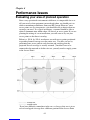
Chapter 4 Performance Issues .............................................. 4-1
Evaluating your area of planned operation.............................4-1
Chapter 5 Before you begin programming… ....................... 5-1
Failure Planning ......................................................................5-2
Chapter 6 Programming for the 802 RF Terminal................ 6-1
Introduction .............................................................................6-1
WD802Term/ActiveX.............................................................6-4
Control Keys for Possible Programming................................6-6
WD802Term ActiveX Concepts.............................................6-7
Portable Printers ....................................................................6-17
Chapter 7 Voice Message Operations................................... 7-1
Why Use Voice Messages and Prompts?................................7-1
802 RF Terminal’s Voice Message Mapping.........................7-2
Programming Voice Messages................................................7-2
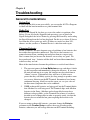
Chapter 8 Troubleshooting .................................................... 8-1
General Considerations ...........................................................8-1
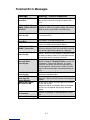
Terminal Error Messages ........................................................8-3
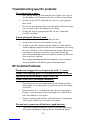
Troubleshooting specific problems.........................................8-4
RF Terminal Problems ............................................................8-4
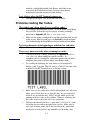
Problems reading Bar Codes...................................................8-5
If you have a problem…..........................................................8-6

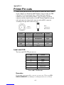
Appendix A Printer Pin-outs......................................................A-1
Appendix B Firmware Upgrades ...............................................B-1
Appendix C Code 39 Specifications .........................................C-3
Appendix D Code 93 Specifications .........................................D-1
Appendix E Codabar Specifications.........................................E-1
Appendix F Code 128 Specifications ....................................... F-1
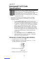
Appendix G Interleaved 2 of 5 Code Specifications............... G-1
Appendix H UPC / EAN Specifications.....................................H-1
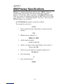
Appendix I MSI/Plessey Specifications ................................... I-1
Appendix J How to scan a bar code ........................................ J-1
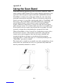
Appendix K Using the Scan Stand............................................K-1
Appendix L Optional Features .................................................. L-1
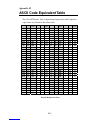
Appendix M ASCII Code Equivalent Table .............................. M-1
Appendix N 802 Display Character Code Mapping.................N-1
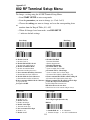
Appendix O 802 RF Terminal Setup Menu .............................. O-1
Index ...........................................................................1
1/06

1-1
Chapter 1
Installation
Components
The 802 Terminal is 802.11b compatible operating between 2399.5 MHz and 2474.5
MHz using direct sequence spread spectrum; it works with Access Points that are
802.11b or 802.11g compatible (b is a subset of g). The components in your 802
Terminal system will vary according to the configuration of your system. Your R/F
Terminal shipment should contain at least:
• An R/F Terminal T802 or LT802 (unit includes keypad and display).
If the R/F Terminal is an LT802 model, it will have an integrated laser
scanner built-in to the body of the terminal. Each terminal is shipped
with a shoulder strap, boot, and Manual.
• An optional Scanner – if you ordered the T802 models instead of the
LT802 models with the built-in laser scanner.
• Optional rechargeable batteries and a 9v power supply.
• 802 Utilities CD ROM – demo programs, Active X development
software, test program, and firmware loader program
Keep the shipping box for the R/F Terminal in the event it is necessary to
return equipment for repair later.
Installation Tips
1. Be sure all Access Points and Terminals have the same SSID and WEP
Key, (if Encryption is used). Terminals are shipped with a SSID of
WORTH DATA.
2. Start with one Terminal. Get everything working with the single
terminal and then add other terminals, being certain that all terminals
have unique IP Device Address.
3. Use the 802 Test Programs to validate that everything is working. If
you have problems, refer to the Trouble Shooting Section.
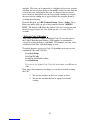
Using the RF Terminal keypad…
The R/F Terminal is turned on by pressing the green
ON/OFF button located in the upper left-hand corner
of the R/F Terminal keypad.
The R/F Terminal has a Shut Down Time feature that allows you to
determine the length of time the R/F Terminal must be inactive before
automatically shutting down to conserve battery power. When the R/F

1-2
Terminal shuts down, simply press the ON/OFF button to resume operation.
The keypad is custom designed for the R/F Terminal operations. It has
numeric and control keys in the non-shifted state, and alpha characters in its
shifted state. You can readily determine if SHIFT is on by the cursor on the
display. When upper case alpha SHIFT is on, the cursor is a large black
rectangle. When SHIFT is off, the cursor is a narrow underline character.
For all prompts which ask for a YES or NO response, the ENTER key, is
the YES reply, and the 0 (zero) key is the NO reply. As you key data, you
will see each character displayed on the screen. If you make a mistake, you
can delete the last character by pressing the DELETE key, or you can clear
all characters displayed on the screen by pressing the CLEAR key.
You can order NiMH rechargeable batteries (L01) from Worth Data along
with a 9v recharging Power Supply that recharges the batteries completely
within 2 hours. When recharging options (batteries or Power Supply) are
ordered with the Terminals, the Terminal's Batteries Setup parameter is set
for recharging "1" which allows the batteries to be recharged under program
control. Otherwise, the batteries shipped are non-rechargeable alkalines
with no recharging options set in the Terminal. However, you may change
the battery type yourself. Using NIMH or alkaline batteries, you should get
24 hours of operation (assuming 1 transaction every 8 seconds).
If you did not order the rechargeable batteries and you change to
rechargeables, you must change the Terminal's Setup to Batteries 1 to allow
recharging. If you want to charge the batteries without having to remove
them from the Terminal, you must use the Worth Data 9v power supply.
You can safely use alkaline batteries in a terminal set for recharging,
providing you don’t plug a power supply into the terminal. Recharging
Alkaline batteries may cause the batteries to explode and leak battery acid
throughout the RF Terminal. Battery acid damage is not covered by the
Worth Data warranty because it not deemed to be “normal use”.
If you are using alkaline batteries (either regular or rechargeables) and
have selected the Rechargeables setting in the Battery setup parameter (See
Chapter 2; RF System Setup), the RF Terminal will generate the following
error message:
Alkaline Batteries
Detected,
Recharge-
ables Are Specified
Do Not Recharge

1-3
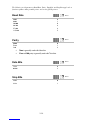
Battery Life Indicator
The R/F Terminal detects low AA batteries and displays the following message:
LOW BATTERIES
Finish, Sign Off
Change Batteries
Hit Any Key_
At this point you have approximately 2 minutes of operational time to finish
your transaction (or note where you are leaving off if in the middle of a
transaction) and sign off. After 2 minutes, the R/F Terminal displays:
CHANGE BATTERIES
UNIT SHUT DOWN_
This message displays for 20 seconds before the R/F Terminal signs off from
the host (if signed on) and then shuts itself down. If you turn it back on
without changing batteries, you may experience constant beeping, intermittent
scanning, and very irritating symptoms that look like equipment failure.
Once you remove the batteries, you have 5 minutes to change them before
you lose the date and time in the Real-Time Clock.
The R/F Terminal also has a battery life indicator. Press the STATUS key
to display the remaining battery life of the AA batteries (as well as the date,
time and other information) as follows:
mm/dd/yy hh:mm
alkBAT-zz%
ServerIP=nnn.nnn.nnn.nnn
DeviceIP=nnn.nnn.nnn.nnn
Ch:=n SSID=xxxxxxxxxxxx
WEP=128 Signal=nn%
alk - when Alkaline batteries are specified in Battery setup
rch- when NiMH or specified in Battery setup
zz=percent or battery life left in numbers i.e. 99, 50, 23
• Server IP either shows the Server's fixed TCPIP address; or if
Device searches out the Server, shows 0.0.0.0.
• Device IP either shows the Device's fixed TCPIP address or, if it
is determined by a DHCP Server, shows 0.0.0.0.
• Ch:=n shows the channel to start using, (the channel of the most
frequently used Access Point).
• SSID=xxxxxxxxxxxx refers to the first 12 characters of the up to
32 character network name.
• WEP=128 or 64 or NO shows how the Device is configured
with an encryption key.

1-4
• Signal=nn% shows the signal strength from the best Access
Point with the same SSID (if already SIGNED ON).
Press the STATUS key again to resume processing
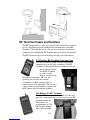
To change the AA batteries:
1. Turn OFF the R/F Terminal.
2. Remove the battery holder door on the back of the R/F Terminal by
pressing down on the grooved portion of the door and pushing outward.
3. Remove the old batteries and insert the new ones, making sure to
orient the batteries with the positive (+) end facing down toward
the bottom of the R/F Terminal.
4. If using rechargeable batteries, make sure that rechargeables are
specified. See the previous page to quickly determine the setting
using the STATUS key.
5. Replace the battery door and turn the reader on using the ON/OFF
switch.
6. Sign ON and resume your application.
Recharging the batteries
1. Be sure you have specified rechargeable batteries in the RF
Terminal's Setup. If you ordered NiMH rechargeable batteries with
a RF Terminal, Worth Data makes the change before shipping. See
Battery in the RF Setup.
2. With the RF Terminal shut off, plug the F15 9V power adapter into
the RF Terminal.
3. The firmware in the terminal then checks the level of charge in the
batteries to see if they need charging, displaying the following message:
Checking Batteries
Please Wait………..
4. If the batteries are already charged, the message will disappear. If
the batteries need charging, the following message is displayed:
Charging Batteries
Please Wait………..
R/F Terminal Menu Functions
There are three modes of operation for the R/F Terminal:
DEVICE SIGN ON Signs R/F Terminal on for two-way
communication with host.
SETUP MODE Accesses Setup parameters for Terminal and Base.
SITE SURVEY Allows you to survey the Access Points strength

1-5
Upon power-up, the R/F Terminal displays the following opening screen:
802 TERMINAL 1XWFUnnn
ServerIP=nnn.nnn.nnn.nnn
DeviceIP=nnn.nnn.nnn.nnn
Ch:=n SSID=xxxxxxxxxxxx
WEP=128 Rnn
HIT ANY KEY
(The opening screen can be bypassed upon power up. See Chapter 2)
• The first line on the screen, 802 TERMINAL WFUnnn, gives the
firmware revision number.
• Server IP either shows the Server's fixed TCPIP address; or if
Device searches out the Server, shows 0.0.0.0.
• Device IP either shows the Device's fixed TCPIP address or if it
is determined by a DHCP Server, shows 0.0.0.0.
• Ch:=nn shows the channel to start using, (the channel of the most
frequently used Access Point, 01-11).
• SSID=xxxxxxxxxxxx refers to the first 12 characters of the up
32 ch character network name.
• WEP=128 or 64 or NO shows how the Device is configured
with an encryption key.
• Rnn=the radio firmware version.
To move on to the first menu item, press any key on the R/F Terminal keypad.
The display now reads:
DEVICE SIGN ON ----->1
SETUP MODE----------->2
SITE SURVEY----------->3
• Press the 1 key to initiate to a two-way communication host
computer program through an Access Point.
• Press the 2 key to change the configuration of the Terminal Device.
• Press the 3 key to survey the intended site for adequate coverage.
This screen can be skipped (see Chapter 2; RF System Setup), causing the R/F
Terminal to automatically enter DEVICE SIGN ON at power up.

1-6
Installing the 802 Terminal Utilities Software
The R/F Terminal system ships with a CD of programs for use with the 802
Terminal communicating with a network. To install any of the programs
found on the Utilities CD, simply insert the CD into your CDROM drive. The
install program should start automatically. If it does not, simply run the
SETUP.EXE program found on the CD. The Setup program is a standard
Windows installer and will offer a Default or Custom installation option. If you
choose default, everything is installed. If you choose Custom, you can choose
any or all of the available programs and samples:
• Demo Programs in VB, Excel, and Delphi
• VB QL3 printer demo program
• 802 Test Program
• Windows 802 RF Terminal Firmware Loader Program
• ActiveX Programming Tool
Demo Programs in VB, Excel, and Delphi
These demos provide samples that illustrate how to use the ActiveX
programming tool and how to create a host application that can manage
multiple terminals.
VB QL3 Printer Demo Program
A Visual Basic demo that shows how to use a QL3 printer attached to a
terminal from your host application
802 Test Program…
The 802 Test Program is provided to help you test your 802 Terminal with a
two-way communication program. Refer to the 802 Test Program’s help for
details on operation.
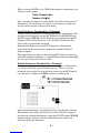
Windows 800 RF Terminal Loader Utility
The R/F Terminal Loader program is a Windows application that allows
you to download new R/F Terminal firmware from Worth Data into your
R/F Terminal using the RF link or a failsafe serial link, (firmware can also
be downloaded over the radio link. See Appendix D; Firmware Upgrades
for details.
ActiveX Programmers Library
The Programmers Library is installed. See Chapter 5 and the installed
ActiveX Manual help file for details on usage.

2-1
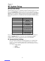
Chapter 2
RF System Setup
RF Terminal Setup
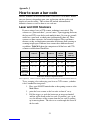
The RF Terminal itself can be configured using the Terminal keypad or by using
the bar coded Setup Menu, which is in the back of your manual. Even if you
configure the RF Terminal using the keypad, you may need the bar coded Setup
Menu to use as a reference. Most users do not need to change anything in the
setup. Some parameters are available only by bar code menu and others only by
keypad:
Bar Code Menu Only Keypad Only
Reset Server IP
Device IP
Starting Channel
SSID
Subnet Mask
WEP Encryption Key
Control Keys Only
Automatic Check Back
Skip Opening Screens
Display of Year
Date and Time
Aiming Dot Duration
Display Backlighting
If you are using the bar coded Setup Menu and are unfamiliar with scanning bar
codes, see Appendix M; How to scan a bar code to learn proper scanning
technique before you begin scanning the bar codes on the Setup Menu.
RF Terminal Default Settings
This is the default configuration of the RF Terminal as it is shipped from
the factory. If you ever need to return the RF Terminal to these default
settings, use the bar coded Setup Menu and scan the following bar codes in
this sequence:
• START SETUP
• RESET
• END SETUP

2-2
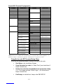
Default RF Terminal Configuration
Parameter Default Setting Parameter Default Setting
Device IP DHCP Server Used Disabled
Server IP Device Searches Start/Stop not transmitted
Subnet Mask 255.255.255.0
Codabar
CLSI format disabled
Starting Channel 1 Disabled
SSID None check digit not transmitted
WEP Encryption None Plessey Code disabled
MSI Code
Label Code4 and 5 disabled
Enabled Enabled
Accumulate Mode ON
Code 128
EAN/UCC 128 disabled
stop/start chs not xmit Code 11 Disabled
check digit disabled RSS-14 Disabled
Caps lock OFF Disabled
Code 39
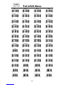
Full ASCII Enabled
Code 93
Full ASCII enabled
Disabled Beep Tone medium
I 2 of 5 Code disabled Date Format mm-dd-yy
6 digit code length Baud Rate 19200
2 of 5 Code
check digit disabled Parity none
Enabled Data Bits 8
UPC supps disabled Stop Bits 1
Batteries Alkaline default UPC-A NSC & check digit
transmitted Speaker
Speaker Volume 5
Headphone Volume 5
UPC-A NSC & check digit
transmitted Laser Options none
Shut Down Time 5 minutes EAN-13 country code &
check digit transmitted Voice Messages 303015
Encryption none EAN-13 country code &
check digit transmitted Control Keys Only no
Display of year 2 digit UPC-E 1st char & check
digit not transmitted Skip opening screens no
Aiming Dot No
UPC-E 1st char & check
digit not transmitted Automatic Check Back No
EAN-8 1st char & check
digit not transmitted Display Backlight Duration 5 seconds
UPC/ EAN
EAN-8 1st char & check
digit not transmitted
*All parameters are set back to their defaults when reset using the bar coded Setup Menu, even
parameters that are changed by keypad only. Shaded items are keypad access only.
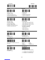
Using the bar code RF Terminal Setup Menu
To use the bar coded Setup Menu, scan these bar codes in this order:
• Start Setup - you should hear 2 beeps
• Setup Parameter bar code (i.e. “Beep Tone”)-you should hear 2
beeps for each scan
• Number bar code that corresponds to the appropriate setting
(i.e. “3” to change the Beep Tone to “high”) - you should hear 2
beeps for each scan
• End Setup-you should hear 3 beeps after END SETUP.

2-3
More than one Setup Parameter can be changed before you scan END
SETUP. For example, if you scanned START SETUP, then “Beep Tone”,
then 3, then “Speaker Operation”, then 1, then END SETUP, this would
change the beep tone to “high”, and turn the speaker "off".
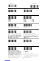
If you are using a Laser Scanner to setup the RF Terminal, the beam will
often cover more than one bar code. Cover any adjacent bar codes before
scanning, and then check the RF Terminal display to make sure the correct
setting was entered.
Using the keypad to setup the RF Terminal
The RF Terminal can be setup via the Terminals' keypad by entering Setup
Mode from the menu. Turn on the Terminal and press any key. You should see:
DEVICE SIGN ON ----->1
SETUP MODE----------->2
SITE SURVEY----------->3
Press the 2 key to change the configuration of the Terminal Device.
At this point, the terminal will ask for a password:
SETUP MODE
PASSWORD?_
Enter WDTRI on the keypad. The next item allows you to choose which
item to configure:
R/F Terminal------->1
Voice Operations->2
Press 1 to enter the RF Terminal Setup.
Now you are in the RF Terminal Setup Menu and can choose from the
following options: RF Setup---0 Batteries--4
BarCodes--1 Speaker---5
RS232-------2 Other------6
Date/Time--3 Exit-------F1
At this point, choose which group you want to configure. Most of the RF
Terminal setup parameters are accessible from the either the keypad Setup
Menu or the bar code Setup Menu. There are only 2 that are available only
from the bar code Setup Menu while there are quite a few options that are
available only from the keypad Setup.

2-4
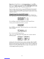
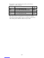
The groups in the keypad Setup Menu contain the following setup parameters:
Setup Group Parameter Setup Group Parameter
RF Setup Device IP Date/Time Set Time
0 Server IP 3 Set Date
Subnet Mask
Date Format
Starting Channel
Display of Year
SSID
WEP Encryption Key Battery Recharging or Not
4
Authentication (only if
WEP is set)
Skip Opening Screen Speaker Speaker Volume
Bar Codes Code 3 of 9 5 Headphone Volume
1 UPC/EAN Beep Tone
Code 2 of 5/I 2 of 5
2 of 5 Length Other Shut Down Time
Code 128 6 Voice Messages
Codabar Laser Options
MSI/ Plessey Aiming Dot Duration
Code 11 Automatic Check Back
Code 93 Control Keys Only
RSS-14 LCD Display Mode
LCD Backlight
RS232 Baud Rate LCD Backlight Duration
2 Parity
Data Bits
Stop Bits
Once you have selected a group to edit, you will see each parameter
displayed in the order listed above. Use the next section of this chapter as a
reference for all RF Terminal Setup Parameters, whether they are
configured using the keypad or the bar coded Setup Menu. Each parameter
is followed by either a key symbol:
and the group you will find the parameter in,
or a bar code symbol:
or both, depending on how the parameter can be configured.
R
F
Setup

2-5
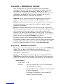
RF Terminal Setup Parameters
Default settings are shown in bold type in this manual and are marked by a * on
the bar code Setup Menu.
The RF Terminal will typically require no setup changes except, Device Address (if
more than one terminal) and enabling bar codes to be read other than UPC or Code 39.
Device IP Address
Get Device IP from DCHP Server 0.0.0.0
Use a Fixed Address nnn.nnn.nnn.nnn
• Every terminal needs a unique Device IP Address. You can use a fixed
IP address, or you can use a DHCP Server (default) to obtain an IP
address. Enter in the address in the format of nnn.nnn.nnn.nnn (where
each n is a value of 0-9); or if you wish to use a DHCP Server, enter
0.0.0.0. The terminal's default setting is to use a DHCP Server.
Server IP Address
Search for Server IP Address 0.0.0.0
Use a Fixed Address nnn.nnn.nnn.nnn
• The terminal communicates with a Server by IP address. The Server IP
address can be found by a search initiated by the terminal, or you can
enter in a fixed IP address for the server. The default setting in the
terminal is to search, (a setting of 0.0.0.0). If you want to use a fixed
server IP address, enter the IP address nnn.nnn.nnn.nnn (where each n
is a value of 0-9.
Subnet Mask
Default Subnet Mask 255.255.255.0
User Defined Subnet Mask nnn.nnn.nnn.nnn
• If you wish to change the default Subnet Mask of 255.255.255.0, then
enter a new mask in the format of nnn.nnn.nnn.nnn.
Starting Channel
Default Starting Channel 1
User Defined Starting Channel 1-11
• The terminal device's channel should be set to the channel of the most
frequently used Access Point to minimize the initial SIGN ON. To save
time, the Terminal Device will try other channels in case the Starting
Channel does not immediately find an Access Point.
R
F
Setup
R
F
Setup
R
F
Setup
R
F
Setup

2-6
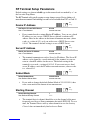
SSID
Default SSID None
User Defined XXXXXXXXXXX
• If wish to restrict terminal device to a specific network name, enter the
name here (up to 32 chs). The default setting is NONE. You will need
to change it in order to sign on to your network. The SSID is case-
sensitive; if you want an SSID with lower case characters, use Shift F2
to go into lower case or you will have to scan the Full ASCII Menu.
WEP Encryption Key
• Here is where you enter the encryption key (WEP). If you want a 64 bit
key, enter the 10 hex number (0-F) string to use. If you want a 128 bit key,
enter the 26 hex (0-F) number string to use. Whatever you enter should
match the Access Point's WEP key.
Authentication
Open System 0
Shared Key 1
• Before a wireless client device can communicate on a network, it must
authenticate to the access point and the network. You must enter a
WEP Encryption key to access the Authentication settings.
• Open System authentication, which is the default setting, is the
preferred method – it allows any device to authenticate with the access
point, but will only allow it to communicate if the WEP keys match.
• Shared Key is allowed to comply with the IEEE 802.11b standard,
however, because of its security flaws; it is not the recommended type
of authentication.
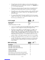
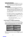
Control Keys Only
No 0
Yes 1
• Several special keys on the RF Terminal keypad can generate a
response automatically, sending a separate message to the host by
simply pressing the appropriate control key (without pressing the
ENTER key afterward). This allows for simple and fast scrolling by the
operator. The arrow keys, Begin, End, and Search are the specific keys
supported. The default setting is to require the ENTER key to be
pressed before data transmission.
Othe
r
R
F
Setup
R
F
Setup
R
F
Setup
R
F
Setup

2-7
• If you set this feature to 1 (YES), in order for the RF Terminal to
transmit the following values, the corresponding Control Key must be
the first key pressed in a data entry sequence. If it is not the first data
entered, the arrow key is ignored.
Control Key on RF Terminal Code transmitted to Host
Up Arrow FS (ASCII 28)
Down Arrow GS (ASCII 29)
Left Arrow RS (ASCII 30)
Right Arrow US (ASCII 31)
Begin ETB (ASCII 23)
End CAN (ASCII 24)
Search VT (ASCII 11)
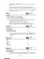
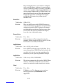
LCD Backlight Display Mode
No 0
Yes 1
The Backlit Display is standard. The default setting is for the LCD
Backlight to be ON. As shipped the Backlight Duration is 5 seconds.
Backlight Duration
Always ON 0
Duration in # of seconds 1..2..5..-9
The Backlight Duration is of no concern unless you have set the LCD
Backlight Display to 1 for YES. This setting determines how long the
Backlight Display is on at startup or when triggered by pressing the F2 key.
Always ON will create a drain on your batteries and you can expect shorter
battery life. The default setting is 5 seconds.
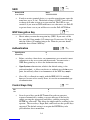
Skip Opening Screens
No 0
Go to Device SIGN ON 1
• Many users want to skip the opening screens and go directly to SIGN
ON communication once their programs are fully operational. Selecting
1 will automatically take the operator to the DEVICE SIGN ON and
into your application program, skipping the screen shown below:
DEVICE SIGN ON ------>1
SETUP MODE------------>2
SITE SURVEY------------>3
R
F
Setup
Other
Othe
r

2-8
If you have skipped the above screen and want to get to it, simply the press
the F1 key.
If your skip the opening screen and you want to check the settings of the
Terminal without having to reset this parameter, just press the Status Key
and the terminal will display six lines as follows:
mm/dd/yy hh:mm
alkBAT-zz%
ServerIP=nnn.nnn.nnn.nnn
DeviceIP=nnn.nnn.nnn.nnn
Ch:=n SSID=xxxxxxxxxxxx
WEP=128 Signal=nn%
alk - when Alkaline batteries are specified in Battery setup
rch- when NiMH batteries specified in Battery setup
zz=percent or battery life left in numbers i.e. 99, 50, 23
• Server IP either shows the Server's fixed TCPIP address; or if
Device searches out the Server, shows 0.0.0.0.
• Device IP either shows the Device's fixed TCPIP address or if it
is determined by a DHCP Server, shows 0.0.0.0.
• Ch:=n shows the channel to start using, (the channel of the most
frequently used Access Point).
• SSID=xxxxxxxxxxxx refers to the first 12 characters of the up to
32 character network name.
• WEP=128 or 64 or NO shows how the Device is configured
with an encryption key.
• Strength=nn% shows the signal strength from the best Access
Point with the same SSID, (if already SIGNED ON).
Press the STATUS key again to resume processing.
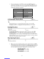
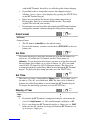
Speaker and Headphone Volume Controls
By selecting Speaker in the keyboard Setup Mode, you get to the options to
control the Speaker/Beeper and Headphone volumes. If you are using
headphones, you will want set the Speaker volume to 0 to conserve batteries.
Volume settings possible are 0-9.
The prompt for Speaker Volume is:
SPEAKER VOLUME
Enter 0-9 for Volume
Control
Current Value is: 5
Speaker

2-9
The prompt for Headphone Volume is:
HEADPHONE VOLUME
Enter 0-9 for Volume
Control
Current Value is: 5
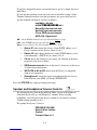
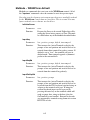
Automatic Check Back
This parameter should not be changed under normal circumstances. After
the host sends a prompt, the Terminal goes to sleep waiting on the operator
to key or scan input in response to the prompt. It waits until the Automatic
Shut Off time or until the operator responds. This parameter sets the time
that the Terminal stops waiting on input from the operator, discards the
current prompt, and goes back to the host to see if there is a change in
instructions. If no change, the host must resend the prompt again because
the Terminal has discarded the original prompt. The host now has the
opportunity to change a prompt. The time can be set in increments of 5
seconds, up to 495 seconds. The default value is 00. The values possible for
entry are 00-99. An entered 99 gives 99x5 seconds, or 495 seconds between
check backs. The Terminal sends back an ASCII 07 for the data back to the
host (ID ASCII 07 CR). This parameter's prompt is:
AUTOMATIC CHECK BACK
Key 00-99.
Current Value: 00
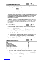
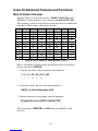
Code 3 of 9 (Code 39)
Enable Code 3 of 9 0
Disable Code 3 of 9 1
Enable Full ASCII Code 39 2
Disable Full ASCII Code 39 3
Enable Code 39 Accumulate Mode 4
Disable Code 39 Accumulate Mode 5
Enable Start/Stop character transmission 6
Disable Start/Stop character transmission 7
Enable Mod 43 Check Digit 8
Disable Mod43 Check Digit 9
Enable Check Digit transmission A
Disable Check Digit transmission B
Caps Lock ON C
Caps Lock OFF D
• The Start and Stop character for Code 39 is the * character. Settings 6
and 7 determine whether or not those characters are transmitted to the
computer along with the data. For example, at setting 6, the data of
1234 would be transmitted as *1234*. Transmitting the start and stop
B
ar
Codes
Other

2-10
characters can be useful if you need to differentiate between data that
comes from a bar code versus data coming from the keypad.
• Enabling use of the Mod 43 check character requires that the last
character of your bar code conform to the Mod 43 check character
specifications. See Appendix E; Code 39 for more information. Enable
transmission (A) will send the check digit data along with the rest of the
bar code data to your computer. To use A, you must also be using 8.
• Caps Lock ON causes lower case letters read as data to be transmitted
to the computer as UPPER CASE, and upper case letters to be
transmitted as LOWER CASE. Numbers, punctuation and control
characters are not affected. Caps Lock OFF means that letters will be
transmitted exactly as read. This setting applies to all bar code types.
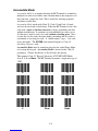
• See Appendix E; Code 39 for more information regarding Accumulate
Mode.
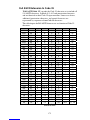
UPC/EAN
Enable UPC/EAN 0
Disable UPC/EAN 1
Enable UPC/EAN Supplements 2
Disable UPC/EAN Supplements 3
Enable transmission of UPC-A NSC or EAN 13 1st 2
digits
4
Disable transmission of UPC-A NSC or EAN-13 1st 2 digits 5
Enable transmission of UPC-A and EAN-13 check digit 6
Disable transmission of UPC-A and EAN-13 check digit 7
Enable transmission of UPC-E NSC and EAN-8 1st digit 8
Disable transmission of UPC-E and EAN-8 1st digit 9
Enable transmission of UPC-E and EAN-8 Check digit A
Disable transmission of UPC-E and EAN-8 check digit B
UPC-E0 Compressed C
UPC-E0 Expanded D
EAN-8 observing 9&A E
EAN-8 forced to transmit 8 digits always F
• Use setting 2 to enable reading of the 2 and 5 digit UPC/EAN supplements
commonly found on magazines and paperback books as well as the
Extended Coupon Codes. Using this setting force left to right reading of
UPC codes to assure that the supplement code is not missed.
• ISBN (International Standard Book Numbering) bar codes are EAN-13
with a 5-digit supplement. If the “Bookland” bar code uses 978 (books) or
977 (periodicals) as the first three digits, then the RF Terminal can transmit
it in the ISBN format. The settings for this are found under the Laser
Options parameter. To enable transmission of the ISBN (prior to January
B
ar
Codes

2-11
2006) format, set the Laser Options parameter to D. To return to the
default of normal EAN-13 transmission, set it to C. For details on ISBN,
see Appendix J, UPC/EAN.
• Use setting 4 and 9 to enable transmission of the NSC character to your
computer. The Number System Character is the leading character in
the bar code. For details, see Appendix J, UPC/EAN.
• Use setting 6 and A to enable transmission of the check digit character
to your computer. The check digit is the last character and is based
upon a calculation performed on the other characters.
• Setting C transmits UPC-E0 bar codes as is; setting D transmits them
with inserted zero’s to make them the same length as a UPC-A bar
code. A NSC of 0 is assumed. It is possible to read UPC-E1 bar codes;
by default this option is disabled. Do not enable UPC-E1 if you plan
on reading EAN-13 bar codes; you may experience partial reads when
reading EAN-13. The UPC-E1 option is set in the 2 of 5 Code
parameter. To enable UPC-E1 reading, set the 2 of 5 Code parameter
to 8. To turn off UPC-E1 reading, set it back to the default of 9.
• If you prefer to transmit UPC-E bar codes in a 6-digit format while EAN-
8 is transmitted in its original 8-digit format use setting F. This will
allow you to use settings 9 and A and still transmit EAN-8 as 8 digits.
• UPC-A can be transmitted in EAN-13 format by adding a leading 0
(USA county code) to the UPC-A data. This setting is found in the
Laser Options parameter. To transmit in EAN-13 format, set the
Laser Options parameter to F. To return to the default (UPC-A
transmitted in original format) set it to E.
Code 128
Disable Code 128 0
Enable Code 128 1
Enable UCC/EAN-128 2
Disable UCC/EAN-128 3
Enable Storage Tek Code (TriOptic Code 39) C
Disable Storage Tek Code (TriOptic Code 39) D
Bar Code ID’s transmitted E
Bar Code ID’s not transmitted F
• UCC/EAN-128 is a subset of Code 128 that follows certain
specifications regarding character content, length and check digits.
Enabling UCC/EAN-128 (2) causes the RF Terminal to look for a Code
128 bar code that begins with the Code 128 F1 (Function 1) character.
See Appendix H: Code 128 for more details.
• The StorageTek Tape Label code is a proprietary variation of Code 39
B
ar
Codes
Page is loading ...
Page is loading ...
Page is loading ...
Page is loading ...
Page is loading ...
Page is loading ...
Page is loading ...
Page is loading ...
Page is loading ...
Page is loading ...
Page is loading ...
Page is loading ...
Page is loading ...
Page is loading ...
Page is loading ...
Page is loading ...
Page is loading ...
Page is loading ...
Page is loading ...
Page is loading ...
Page is loading ...
Page is loading ...
Page is loading ...
Page is loading ...
Page is loading ...
Page is loading ...
Page is loading ...
Page is loading ...
Page is loading ...
Page is loading ...
Page is loading ...
Page is loading ...
Page is loading ...
Page is loading ...
Page is loading ...
Page is loading ...
Page is loading ...
Page is loading ...
Page is loading ...
Page is loading ...
Page is loading ...
Page is loading ...
Page is loading ...
Page is loading ...
Page is loading ...
Page is loading ...
Page is loading ...
Page is loading ...
Page is loading ...
Page is loading ...
Page is loading ...
Page is loading ...
Page is loading ...
Page is loading ...
Page is loading ...
Page is loading ...
Page is loading ...
Page is loading ...
Page is loading ...
Page is loading ...
Page is loading ...
Page is loading ...
Page is loading ...
Page is loading ...
Page is loading ...
Page is loading ...
Page is loading ...
Page is loading ...
Page is loading ...
Page is loading ...
Page is loading ...
Page is loading ...
Page is loading ...
Page is loading ...
Page is loading ...
Page is loading ...
Page is loading ...
Page is loading ...
Page is loading ...
Page is loading ...
Page is loading ...
Page is loading ...
Page is loading ...
Page is loading ...
Page is loading ...
Page is loading ...
Page is loading ...
Page is loading ...
Page is loading ...
Page is loading ...
Page is loading ...
Page is loading ...
Page is loading ...
Page is loading ...
Page is loading ...
Page is loading ...
Page is loading ...
Page is loading ...
Page is loading ...
-
 1
1
-
 2
2
-
 3
3
-
 4
4
-
 5
5
-
 6
6
-
 7
7
-
 8
8
-
 9
9
-
 10
10
-
 11
11
-
 12
12
-
 13
13
-
 14
14
-
 15
15
-
 16
16
-
 17
17
-
 18
18
-
 19
19
-
 20
20
-
 21
21
-
 22
22
-
 23
23
-
 24
24
-
 25
25
-
 26
26
-
 27
27
-
 28
28
-
 29
29
-
 30
30
-
 31
31
-
 32
32
-
 33
33
-
 34
34
-
 35
35
-
 36
36
-
 37
37
-
 38
38
-
 39
39
-
 40
40
-
 41
41
-
 42
42
-
 43
43
-
 44
44
-
 45
45
-
 46
46
-
 47
47
-
 48
48
-
 49
49
-
 50
50
-
 51
51
-
 52
52
-
 53
53
-
 54
54
-
 55
55
-
 56
56
-
 57
57
-
 58
58
-
 59
59
-
 60
60
-
 61
61
-
 62
62
-
 63
63
-
 64
64
-
 65
65
-
 66
66
-
 67
67
-
 68
68
-
 69
69
-
 70
70
-
 71
71
-
 72
72
-
 73
73
-
 74
74
-
 75
75
-
 76
76
-
 77
77
-
 78
78
-
 79
79
-
 80
80
-
 81
81
-
 82
82
-
 83
83
-
 84
84
-
 85
85
-
 86
86
-
 87
87
-
 88
88
-
 89
89
-
 90
90
-
 91
91
-
 92
92
-
 93
93
-
 94
94
-
 95
95
-
 96
96
-
 97
97
-
 98
98
-
 99
99
-
 100
100
-
 101
101
-
 102
102
-
 103
103
-
 104
104
-
 105
105
-
 106
106
-
 107
107
-
 108
108
-
 109
109
-
 110
110
-
 111
111
-
 112
112
-
 113
113
-
 114
114
-
 115
115
-
 116
116
-
 117
117
-
 118
118
-
 119
119


Ask a question and I''ll find the answer in the document
Finding information in a document is now easier with AI
in other languages
- italiano: Worth Data 802 RF Manuale utente
Related papers
Other documents
-
Intermec 700 Series 730B User manual
-
LXE MX3-CE Reference guide
-
 Psion Teklogix 7530 User manual
-
 Psion Teklogix GM37530RA2020 User manual
-
 Psion Teklogix 7545 User manual
-
 Psion Teklogix Vehicle-Mount Computer 8260 User manual
-
-
 Psion Teklogix 9160 G2 User manual
-
Zebra CPCL Owner's manual
-


