MULTIPLEX Funcub Owner's manual

Category
Remote controlled toys
Type
Owner's manual

This manual is also suitable for

1
F
GB
D
E
I
Baukasten / kit # 21 4243
Bauanleitung 3 ... 8
Notice de construction 9 ... 14
Building instructions 15 ... 24
Instruzioni di montaggio 25 ... 29
Instrucciones de montaje 30 ... 35
Ersatzteile
Replacement parts
Pièces de rechanges
Parti di ricambio
Repuestos
36 ... 37
© Copyright by MULTIPLEX 2010 Version 1.0
2
D
F
GB
I
E
Sicherheitshinweise
Prüfen Sie vor jedem Start den festen Sitz des Motors und der Luftschraube - insbesondere nach dem Transport, härteren Landungen
sowieAbstürzen. Prüfen Sie ebenfalls vor jedem Start den festen Sitz und die richtige Position der Tragflächen auf dem Rumpf.
Akku erst anstecken, wenn Ihr Sender eingeschaltet ist und Sie sicher sind, dass das Bedienelement für die Motorsteuerung auf "AUS"
steht.
Im startbereiten Zustand nicht in den Bereich der Luftschraube greifen!
Vorsicht in der Luftschraubendrehebene - auch Zuschauer zur Seite bitten!
Zwischen den Flügen die Motortemperatur durch vorsichtige Fingerprobe prüfen und
vor einem Neustart den Motor ausreichend abkühlen lassen. Die Temperatur ist richtig, wenn Sie den Motor problemlos berühren
können. Insbesondere bei hohen Außentemperaturen kann dieses einige Minuten dauern.
Denken Sie immer daran: Niemals auf Personen und Tiere zufliegen.
Conseils de sécurité
Avant chaque décollage, vérifiez la fixation du moteur et de l'hélice, notamment après le transport, après les atterrissages violents et
après un “Crash”. Vérifiez également, avant chaque décollage la fixation ainsi que le positionnement de l’aile par rapport au fuselage.
Ne branchez l’accu de propulsion que si vous êtes sûr que votre émetteur est allumé et que l’élément de commande moteur est en
position “ARRET”.
Ne mettez pas vos doigts dans l’hélice! Attention à la mise en marche, demandez également aux spectateurs de reculer.
Entre deux vols, vérifiez en posant un doigt dessus, la température du moteur, laissezle refroidir suffisamment avant le prochain
décollage. La température est correcte si vous pouvez maintenir votre doigt ou votre main sur le moteur. Le temps de refroidissement
peut varier jusqu’à 15 minutes s’il fait particulièrement chaud.
Pensez-y toujours: ne volez jamais vers ou au-dessus des personnes ou des animaux.
Safety notes
Before every flight check that the motor and propeller are in place and secure - especially after transporting the model, and after hard
landings and crashes. Check also that the wing is correctly located and firmly secured on the fuselage before each flight.
Don’t plug in the battery until you have switched on the transmitter, and you are sure that the motor control on the transmitter is set to
“OFF”.
When the model is switched on, ready to fly, take care not to touch the propeller. Keep well clear of the propeller disc too, and ask
spectators to stay back.
Allow the motor to cool down after each flight. You can check this by carefully touching the motor case with your finger. The
temperature is correct when you can hold your finger on the case without any problem. On hot days this may take up to 15 minutes.
Please keep in mind at all times: don’t fly towards people or animals.
Note di sicurezza
Prima di ogni decollo controllare che il motore e la eliche siano fissati stabilmente - specialmente dopo il trasporto, atterraggi duri e se il
modello è precipitato. Controllare prima del decollo anche il fissaggio e la posizione corretta delle ali sulla fusoliera.
Collegare la batteria solo quando la radio è inserita ed il comando del motore è sicuramente in posizione ”SPENTO”.
Prima del decollo non avvicinarsi al campo di rotazione della eliche. Attenzione alla eliche in movimento - pregare che eventuali spettatori
si portino alla dovuta distanza di sicurezza!
Tra un volo e l’altro controllare cautamente con le dita la temperatura del motore e farli raffreddare sufficientemente prima di ogni nuovo
decollo. La temperatura è giusta se si possono toccare senza problemi. Specialmente con una temperatura esterna alta questo può
durare fino a 15 minuti.
Fare attenzione: Non volare mai nella direzione di persone ed animali.
Advertencias de seguridad
Compruebe antes de cada despegue que el motor y la hélice estén fuertemente sujetados, sobretodo después de haberlo transportado,
de aterrizajes más fuertes así como después de una caída. Compruebe igualmente antes de cada despegue que las alas estén bien
sujetas y bien colocadas en el fuselaje.
Conectar la batería, cuando la emisora esté encendida y Usted esté seguro que el elemento de mando para el motor esté en ”OFF”.
No meter la mano en la zona inmediata a la hélice cuando el avión esté a punto de despegar. ¡Cuidado con la zona de la hélice! ¡Pedir a
los espectadores que se aparten!
Entre los vuelos hay que comprobar cuidadosamente la temperatura del motor con el dedo y dejar que el motor se enfríe antes de volver
a despegar. La temperatura es correcta, si puede tocar el motor sin problemas. Sobretodo en el caso de temperaturas del ambiente muy
altas, esto puede tardar unos 15 minutos.
Recuerde: No volar nunca hacía personas o animales.
3
# 21 4243
D
Machen Sie sich mit dem Bausatz vertraut!
MULTIPLEX - Modellbaukästen unterliegen während der Produktion einer ständigen Materialkontrolle. Wir hoffen, dass Sie mit
dem Baukasteninhalt zufrieden sind. Wir bitten Sie jedoch, alle Teile (nach Stückliste) vor Verwendung zu prüfen, da bearbeitete
Teile vom Umtausch ausgeschlossen sind. Sollte ein Bauteil nicht in Ordnung sein, sind wir nach Überprüfung gerne zur
Nachbesserung oder zum Umtausch bereit. Senden Sie das Teil, bitte ausreichend frankiert, an unsere Modellbauabteilung
und fügen Sie unbedingt
die vollständig ausgefüllte Reklamationsmeldung (Formular) bei. Wir arbeiten ständig an der
technischen Weiterentwicklung unserer Modelle. Änderungen des Baukasteninhalts in Form, Maß, Technik, Material und Aus-
stattung behalten wir uns jederzeit und ohne Ankündigung vor. Bitte haben Sie Verständnis dafür, dass aus Angaben und
Abbildungen dieser Anleitung keine Ansprüche abgeleitet werden können.
Empfohlene Ausrüstung:
Empfänger ab RX 7 DR light M-LINK 2,4 GHz Best. Nr. 5 5810
oder RX-9-DR M-LINK 2,4 GHz Best. Nr. 5 5812
Empfänger RX-7-Synth IPD 35 MHz A-Band Best.-Nr. 5 5880
alternativ 40/41 MHz Best.-Nr. 5 5882
2 Servos Tiny-S (Seite, Höhe) Best. Nr. 6 5121
2 Servos Nano-S (Quer) Best. Nr. 6 5120
Optional: weitere 2 bzw. 3 Servos Nano-S Best. Nr. 6 5120
(für Landeklappen und Schleppkupplung)
Antriebssatz:
Antriebsatz „FunCub“ Best. Nr. 33 2649
mit Brushless-Motor, Regler, Propeller,
Mitnehmer und Zubehör.
Akkuempfehlung:
Li-BATT eco 3/1-2000 (M6) Best. Nr. 15 7231
Klebstoff: Zacki ELAPOR
® 20g VE 20 Best.-Nr. 59 2727
Zacki ELAPOR ® Super liquid 10g VE20 Best.-Nr. 59 2728
Tipp! Kostenvorteil
Antriebssatz „FunCub“ Li-BATT powered Best. Nr. 33 3649
Wie oben jedoch zusätzlich mit Antriebsakku Li-BATT eco 3/1-2000 (M6).
Werkzeuge:
Schere, Klingenmesser, Kombizange, Schraubendreher.
Technische Daten:
Spannweite 1400 mm
Länge über alles 980 mm
Fluggewicht ca. 1130 g
Flächeninhalt 38 dm²
Flächenbelastung ab 30 g/dm²
RC-Funktionen Höhe, Seite, Querruder, Motor.
Landeklappen und Schleppkupplung (optional)
Achtung!
Ferngesteuerte Modelle, insbesondere Flugmodelle, sind kein Spielzeug im üblichen Sinne. Ihr Bau und
Betrieb erfordert technisches Verständnis, ein Mindestmaß an handwerklicher Sorgfalt sowie Disziplin
und Sicherheitsbewusstsein. Fehler und Nachlässigkeiten beim Bau und Betrieb können Personen- und
Sachschäden zur Folge haben. Da der Hersteller keinen Einfluss auf ordnungsgemäßen Zusammenbau,
Wartung und Betrieb hat, weisen wir ausdrücklich auf diese Gefahren hin.
4
Wichtiger Hinweis
Dieses Modell ist nicht aus Styropor ™! Daher sind Verklebungen mit Weißleim, Polyurethantan oder Epoxy nicht
möglich. Diese Kleber haften nur oberflächlich und platzen im Ernstfall einfach ab. Verwenden Sie nur
Cyanacrylat-/Sekundenkleber mittlerer Viskosität, vorzugsweise unser Zacki -ELAPOR® # 59 2727, der für
ELAPOR® Partikelschaum optimierte und angepasste Sekundenkleber.
Bei Verwendung von Zacki-ELAPOR
® können Sie auf Kicker oder Aktivator weitgehend verzichten. Wenn Sie
jedoch andere Kleber verwenden, und auf Kicker/Aktivator nicht verzichten können, sprühen Sie aus gesundheitlichen
Gründen nur im Freien.
Vorsicht beim Arbeiten mit allen Cyanacrylatklebern (CA). Diese Kleber härten u.U. in Sekunden, daher nicht mit den
Fingern und anderen Körperteilen in Verbindung bringen. Zum Schutz der Augen unbedingt Schutzbrille tragen!
1. Vor dem Bau
Prüfen Sie vor Baubeginn den Inhalt Ihres Baukastens. Dazu
sind die Abb. 1 + 2 und die Stückliste hilfreich.
2. Der Rumpf
Zunächst die Verschlussklammern 22 und die Motorträger 37
in beide Rumpfhälften einkleben.
Abb. 3
3. Servoeinbau
Die Servos für „Seite“ und „Höhe“ in die Rumpfhälften 3+4
einpassen und an den Servolaschen einkleben. Die
Servokabel mit Kreppklebeband fixieren, damit die Kabel und
Stecker keinen Schaden anrichten können und später beim
Zusammenkleben nicht stören.
Abb. 4
4. Bowdenzüge
Die Bowdenzüge 54/56 u. 55/57 vorbereiten.Außen- und Innen-
rohre ggf. auf Länge anpassen und die Stahldrähte 52/53 ein-
führen. Die Gestängeanschlüsse in die Ruderhörner am äu-
ßeren Loch montieren. Beachten Sie, dass das Z-Gestänge
in das zweite Loch von außen am Servoarm eingehängt wird.
Dabei die Rumpfhälften so auflegen, dass der Rumpf beim
Kleben gerade bleibt. Die Bowdenzüge einkleben.
Abb. 5-6
5. Tragflächengegenlager vormontieren
Die Flügelgegenlager 33+34 zusammenklipsen und kleben.
Ggf. die Kombizange benutzen. Die so vorbereiteten Flügel-
gegenlager in die rechte Rumpfhälfte einkleben.
Abb. 7
6. Rumpfhälften verkleben
Die Rumpfhälften 3/4 zunächst ohne Klebstoff zusammenfü-
gen. Wenn alles passt, den Rumpf verkleben. In der Härte-
phase den Rumpf ausrichten.
Abb. 7
7. Gestängeanschluss vorbereiten
Den Gestängeanschluss 25 für das Höhenruder 8 in die äu-
ßerste Bohrung des Ruderhorns 24 stecken und mit der U-
Scheibe 26 und der Mutter 27 befestigen.
Achtung: Beachten Sie die Einbaurichtung. Die Muttern mit
Gefühl anziehen, der Gestängeanschluss muss noch be-
weglich bleiben und anschließend die Mutter auf dem Gewin-
de mit einem Abstrich (Nadel) Sekundenkleber oder Lack si-
chern. Den Inbusgewindestift 28 mit dem Inbusschlüssel 29
im Gestängeanschluss 25 vormontieren. Das Ruderhorn 24
(mit der Lochreihe nach vorn) in das Höhenruder 8 einkleben
Abb. 8
8. Höhenleitwerk einkleben
Das Höhenruder zur Probe auf den Rumpf setzen und prüfen,
ob es sich gerade ausrichten lässt - ggf. nacharbeiten. An-
schließend kleben und sofort ausrichten. Abb. 9
9. Seitenleitwerk mit Heckfahrwerk
Den Draht für das Spornrad 76 durch das Einklebespornlager
36 und durch das Einkleberuderhorn 35 stecken und so kurz
wie möglich nach Abb. 10 auf 90° abbiegen.
Das Einkleberuderhorn 35 im Seitenruder 9 einkleben, aber
nur unten CA Kleber auftragen. Dann über dem Ruderhorn
einen Schlitz von ca.
1,5 mm für den Sporndraht einschneiden.
Ggf. überschüssigen Kleber abwischen. Den Spornraddraht
76 über das Ruderhorn 35 einschwenken, ausrichten und mit
CA sorgfältig verkleben. Den Gestängeanschluss montieren,
die Mutter mit einem Tropfen Lack oder Kleber sichern.
Abb. 11
Das Spornrad 77 montieren. Dazu zunächst eine Arretierung
78 auf den Draht schieben, dann das Rad und die zweite Arre-
tierung.
Die Arretierungen 78 mit CA Kleber sichern.
Abb. 12
10. Seitenleitwerk einkleben
Das Seitenleitwerk 9 vormontiert im Rumpf und Höhenleitwerk
einpassen und einkleben.
Abb. 13
11. Hauptfahrwerk
Im Rumpf wird der „Fahrwerkshalter“ 74 eingeklebt. Einmal
eindrücken, den Sitz kontrollieren und dann einkleben.
Abb. 14
Das Hauptfahrwerk 70 vormontieren.
Rechts und links je einen Stellring 72 in Verbindung mit je
einem Inbus Gewindestift 73 befestigen. Die Räder 71 aufset-
zen und mit weiteren Stellringen 72 wieder in Verbindung mit
den Gewindestiften 73 befestigen. Die Räder so justieren,
dass sie frei laufen. Abb. 15
Das Fahrwerk 70 einrasten und mit der Schraube 75 sichern.
Abb.15
12. Die Tragflächen
Die Tragflächenhälften 6/7 werden
nicht verklebt!
Bevor Sie die Holme einkleben, fügen Sie die Holme 50/51
und Holmhalter 30/31 zunächst probehalber zusammen.
Beachten Sie: Der vordere Holmhalter 30 ist höher als der
hintere 31 !
Wenn alles passt, werden die Holme 50/51 und Holmhalter
30/31 nur in der rechten Tragflächenhälfte verklebt.
Abb. 16
Nun die Holme in die freie Seite der Holmhalter stecken (nicht
kleben!). Die linke Tragfläche auf die Holme und Halter schie-
ben, den Sitz kontrollieren. Nun Kleber in das Holmbett des
linken Flügels eingeben und die Flügelhälfte positioniert ein-
kleben.
Abb. 17
5
13. Querruder und Landeklappen gängig machen
An den Tragflächen 6 und 7 die Querruder seitlich gemäß der
Vertiefung freischneiden. Die Scharnierkanten durch hin- und
herbewegen „gängig“ machen, jedoch nicht überdehnen - kei-
nesfalls die Ruder abtrennen!
Sollen die Landeklappen verwendet werden, schneiden Sie
diese ebenfalls seitlich frei und trennen Sie diese von der
Tragfläche ab. Die Trennstelle sauber planschleifen.
Abb 18/19
Die Klappe wird formschlüssig am Tragflügel positioniert und
mit Kreppband fixiert. Nun passt auch die Klappe in die Flügel-
kontur. Falls die Landeklappen nicht aktiviert werden, kann
der Überstand hinten abgeschnitten werden.
Abb. 20
Falls die Landeklappen aktiviert werden, montieren Sie die
sechs Offsetschaniere aus den Teilen 41 und 42, vor.
Alle Klebenester sind vor dem Einkleben der Ruderhörner mit
Aktivator hauchdünn zu besprühen und ca. 60 Sekunden ab-
lüften lassen. Die vorbereiteten Scharniere in die Nester der
Landeklappen eingekleben.
Abb. 21
In die beiden Ruderhörner für die Querruder die Kardanbolzen
43 in die Bohrung der Ruderhörner stecken.
Den Inbusgewindestift 28 mit dem Inbusschlüssel 29 im
Kardanbolzen 43 vormontieren.
Die Ruderhörner 41 und 44 in das Nest der Querruder bzw.
der Landeklappen einkleben.
Abb. 22
14. Querruderservos montieren
Stellen Sie die Servos mit der Fernsteuerung auf „Neutral“.
Montieren Sie die Servohebel so auf den Servos, dass die
Hebel in Neutralstellung 90° seitlich überstehen - 1x links und
1x rechts (spiegelbildlich).
Die Servos in die Formnester der Tragflächen 6 und 7 einpas-
sen. Dabei liegt der Abtrieb in Flugrichtung vorne.
Dem verwendeten Servotyp entsprechend, können kleinere
Anpassungsarbeiten notwendig werden. Zum Einkleben je-
weils einen Tropfen Heiß- oder CA-Kleber in die Schlitze für
die Servolaschen am Flügel geben und das Servo sofort in
das Nest drücken - ggf. anschließend nachkleben.
15. Querrudergestänge montieren
Die Querrudergestänge 45 werden beim Servo im äußeren
Loch des Abtriebshebels mit der Z-Biegung eingehängt und
bei Neutralstellung der Ruder im Gestängeanschluß des
Ruderhorns mit dem Gewindestift 28 festgeklemmt.
16. Landeklappenservos montieren
Stellen Sie die Servos mit der Fernsteuerung auf „Neutral“.
Montieren Sie die langen Servohebel so auf die Servos, dass
die Hebel in Neutralstellung 70° (Schablone auf Abb.23) po-
sitioniert sind - 1x links und 1x rechts (spiegelbildlich).
ggf. die Schablone ausschneiden.
Das Landeklappengestänge 46 wird ca. 23 mm vom Dreh-
punkt entfernt mit der Z-Biegung im Abtriebshebel einhängt
und auf der anderen Seite durch den Gestängeanschluss 25
gesteckt. Die Ruder und das Servo in Neutralstellung bringen
und das Gestänge mit dem Gewindestift 28 festklemmen.
Abb. 24
Ist alles korrekt zusammengebaut, können Sie die Tragflächen-
hälften in der Mitte wieder auseinander ziehen.
17. Schleppkupplung
Die Schleppkupplung 47 kann jederzeit nachgerüstet werden.
Kleben Sie diese in die Aussparung der rechten Tragfläche
ein. Stellen Sie das Servo auf „Neutral“, und montieren Sie
den Servoarm so, dass er in Flugrichtung nach vorne zeigt.
Das Schleppkupplungsgestänge 48 wird in den Hebelarm
des Servos eingehängt und entsprechend gebogen und ge-
kürzt. Das Servo wird in die Aussparung auf der Unterseite der
Tragfläche mit Heiß- oder CA-Kleber eingeklebt. Abb. 25
18. Kontrollmontage
Tragflächen zusammenstecken. Mit den Kunststoffschrauben
32 werden die Tragflächen mit dem Rumpf verschraubt. Durch
die Formgebung der Tragfläche in Richtung Rumpf ist der
Flügel gegen Abrutschen gesichert.
Abb. 26
19. Antriebssatz:
AlsAntriebssatz ist der MULTIPLEXAntriebssatz FunCub Best.-
Nr. 33 2649 vorgesehen. Stromaufnahme mit 3S LiPo und
beiliegendem Prop:
ca. 23A
Es kommt der Motor: Himax C 3516-0840, Regler MULTIcont
BL-30 S-BEC, Propeller 13x4“ und ein Mitnehmer mit Spinner
zum Einsatz.
Abb.27
20. Den Motorspant auf die Motorträger montieren
In Verbindung mit den Motorträgern 37 und dem Motorspant
38 kann der Seitenzug und der Motorsturz verändert werden.
Der Träger ist bereits asymmetrisch eingebaut, wenn die 4
Stellschrauben 39 bündig eingedreht sind, haben Sie maxi-
malen Seitenzug und keinen Sturz. Wir empfehlen folgende
Grundeinstellung. Dabei ist von hinten(!) auf den Motorspant
zu sehen. Abb. 28
Die Madenschrauben sollten wie angegeben auf der Rück-
seite des Motorspants überstehen:
Links oben: 3,0 mm
Rechts oben: 3,0 mm
Links unten 1,5 mm
Rechts unten: 1,5 mm
Ein Feinabgleich ist beim Einfliegen nötig!
21. Motor einbauen
Den Motor mit den im Antriebssatz enthaltenen Schrauben
am Motorspant 38befestigen und nach Abb. 27 mit den Schrau-
ben 40 einbauen.
22. Kabinenhauben-Verschlusszapfen einkleben
Die Kabinenhaube 5 wird von vorne in Richtung Tragfläche in
den Rumpf gesteckt und dann erst vorne nach unten geklappt.
Die beiden Verschlusszapfen 23 bündig probehalber einstek-
ken und positionieren. An die Verzahnung dickflüssigen
Sekundenkleber angeben, dann die Verschlusszapfen in die
Schlitze der Kabinenhaube einsetzen. Die Kabinenhaube in
den Rumpf einführen und mit den Verschlusszapfen in die
Verschlussklammern 22 einschnappen lassen. Sofort am
Rumpf ausrichten. Etwa 1 Minute warten und die Haube an-
schließend vorsichtig öffnen. Die Klebestellen an den
Verschlusszapfen ggf. nachkleben.
Abb. 29
6
23. Flugakku und Empfänger einbauen
Der Raum für den Flugakku ist unter der Kabinenhaube und
reicht bis unter die Tragflächenauflage. Verwenden Sie die
beiliegenden Klettbandstreifen 20/21 in diesem Bereich, um
den Akku zu befestigen.
Seitlich daneben in der Bordwand hat der Regler seinen Platz.
Der Empfänger wird mit Klettband 20/21 unter der Tragflächen-
auflage positioniert.
Abb. 30
Den VerbindungssteckerAkku / Regler für den Motor erst
einstecken, wenn Ihr Sender eingeschaltet ist und Sie si-
cher sind, dass das Bedienelement für die Motorsteuerung
auf „AUS“ steht.
Stecken Sie die Servostecker in den Empfänger. Schalten Sie
den Sender ein und verbinden Sie im Modell den Antriebsakku
mit dem Regler und den Regler mit dem Empfänger.
Nun kurz den Motor einschalten und die Drehrichtung des Pro-
pellers kontrollieren (beim Probelauf das Modell festhalten
und lose, leichte Gegenstände vor und hinter dem Modell ent-
fernen). Die Drehrichtung wird ggf. am Motoranschluss korri-
giert - keinesfalls am Antriebsakku.
Vorsicht: Im Luftschraubenbereich besteht erhebliche Ver-
letzungsgefahr!
24. Antennenverlegung auf der Rumpfunterseite
Die Antenne des Empfängers wird nach unten aus dem Rumpf
auf die Rumpfunterseite und dann in Richtung Leitwerk ge-
führt. Dazu von der Rumpfinnenseite einen Durchbruch nach
außen durchstechen – die Antenne von innen durchfädeln und
am Rumpf mit einem Klebestreifen fixieren. Falls die Antenne
länger ist (35/40 Mhz), das freie Ende als „Schleppantenne“
nachziehen.
25. Ruderausschläge einstellen
Um eine ausgewogene Steuerfolgsamkeit des Modells zu er-
zielen, ist die Größe der Ruderausschläge richtig einzustel-
len.
Höhenruder nach oben - Knüppel gezogen 25 mm
unten - Knüppel gedrückt 22 mm
Seitenruder nach links
und rechts je 25 mm.
Querruder nach oben 22 mm
und nach unten 12 mm
Die Ruderausschläge werden jeweils an der tiefsten Stelle
der Ruder gemessen.
Falls Ihre Fernsteuerung diese Wege nicht ganz zulässt, ist
das kein Problem - nur bei größerer Abweichung müssen Sie
den jeweiligen Gestängeanschluss umsetzen.
Wird das Modell als Trainer geflogen, werden die Ruderaus-
schläge auf ca. 50-60% reduziert
26. Noch etwas für die Schönheit
Dazu liegt dem Bausatz ein mehrfarbiger Dekorbogen 2 bei.
Die einzelnen Schriftzüge und Embleme werden ausgeschnit-
ten und nach unserer Vorlage (Baukastenbild) oder nach ei-
genen Vorstellungen aufgebracht. Das Dekor muss beim er-
sten Mal „sitzen“ (Klebekraft).
27. Auswiegen des Schwerpunkts
Um stabile Flugeigenschaften zu erzielen, muss Ihr Modell -
wie jedes andere Flugzeug auch - an einer bestimmten Stelle
im Gleichgewicht sein. Montieren Sie Ihr Modell flugfertig und
setzen den Antriebsakku ein.
Der Schwerpunkt wird 80 mm von der Vorderkante des Trag-
flügels am Rumpf gemessen und angezeichnet.
Hier mit den Fingern unterstützt, soll das Modell waagerecht
auspendeln. Durch Verschieben des Antriebsakkus sind Kor-
rekturen möglich. Ist die richtige Position gefunden, stellen
Sie durch eine Markierung im Rumpf sicher, dass der Akku
immer an derselben Stelle positioniert wird. Die Schwerpunkt-
einstellung ist nicht kritisch - 10mm vor oder zurück ist kein
Problem.
Abb. 31
28. Vorbereitungen für den Erstflug
Für den Erstflug warten Sie einen möglichst windstillen Tag
ab. Besonders günstig sind oft die Abendstunden.
Vor dem ersten Flug unbedingt einen Reichweitentest nach
den Vorgaben Ihres Fernsteuerlieferanten durchführen!
Falls etwas unklar ist, sollte auf keinen Fall ein Start erfolgen.
Geben Sie die gesamte Anlage (mit Akku, Schalterkabel,
Servos) in die Serviceabteilung des Geräteherstellers zur Über-
prüfung.
Erstflug ...
Das Modell wird immer gegen den Wind gestartet.
Falls Sie Einsteiger oder noch unsicher sind, lassen Sie sich
beim Erstflug besser von einem geübten Helfer unterstüt-
zen.
29. Start von der Piste
Steht eine Piste zur Verfügung wird das Modell am sichersten
vom Boden gestartet.
Nach dem Einfliegen werden Sie auch ohne Piste im rauen
Gelände starten und landen können – gerade das ist der Reiz
des Modells.
30. Start aus der Hand
Hinweis für den Einsteiger: Machen Sie in keinem Fall Start-
versuche mit stehendem Motor!
Das gibt immer Schrott! Das Modell wird mit Halbgas aus der
Hand gestartet - immer gegen den Wind.
Lassen Sie sich das Modell von einem geübten Werfer star-
ten.
Mit zwei, drei Schritten Anlauf und einem geraden Wurf gelingt
der Handstart. Danach den Steigflug korrigieren - gleichmä-
ßig flach steigen und Fahrt halten!
Nach Erreichen der Sicherheitshöhe die Ruder über die Trim-
mung am Sender so einstellen, dass das Modell geradeaus
fliegt. Machen Sie sich in ausreichender Höhe vertraut, wie
das Modell reagiert, wenn der Akku leer wird. Simulieren Sie
Landeanflüge in größerer Höhe, so sind Sie vorbereitet, wenn
der Antriebsakku wirklich leer ist und der Antrieb ausfällt.
Versuchen Sie in der Anfangsphase, insbesondere bei der
Landung, keine „Gewaltkurven“ dicht über dem Boden. Lan-
den Sie sicher und nehmen besser ein paar Schritte in Kauf,
als mit Ihrem Modell bei der Landung einen Bruch zu riskie-
ren.
31. Sicherheit
Sicherheit ist das oberste Gebot beim Fliegen mit Flug-
modellen.
Eine Haftpflichtversicherung ist obligatorisch. Falls Sie in ei-
nen Verein oder Verband eintreten, können Sie diese Versi-
cherung dort abschließen. Achten Sie auf ausreichenden Ver-
sicherungsschutz. Halten Sie Modelle und Fernsteuerung im-
mer absolut in Ordnung. Informieren Sie sich über die Lade-
7
technik für die von Ihnen verwendeten Akkus. Benutzen Sie
alle sinnvollen Sicherheitseinrichtungen, die angeboten wer-
den. Informieren Sie sich in unserem Hauptkatalog; MULTI-
PLEX-Produkte sind von erfahrenen Modellfliegern aus der
Praxis für die Praxis gemacht.
Fliegen Sie verantwortungsbewusst! Anderen Leuten dicht
über die Köpfe zu fliegen ist kein Zeichen für wirkliches Kön-
nen, der wirkliche Könner hat dies nicht nötig. Weisen Sie
auch andere Piloten in unser aller Interesse auf diese Tatsa-
che hin.
Fliegen Sie immer so, dass weder Sie noch andere in Gefahr
kommen. Denken Sie immer daran, dass auch die allerbeste
Fernsteuerung jederzeit durch äußere Einflüsse gestört wer-
den kann. Auch langjährige, unfallfreie Flugpraxis ist keine
Garantie für die nächste Flugminute.
Wir, das MULTIPLEX -Team, wünschen Ihnen beim Bauen und
später beim Fliegen viel Freude und Erfolg.
MULTIPLEX Modellsport GmbH &Co. KG
Produktbetreuung und Entwicklung
Klaus Michler
8
Stückliste FunCub
Lfd. Stück Bezeichnung Material Abmessungen
1 1 Bauanleitung
2 1 Dekorbogen 500 x 880 mm
3 1 Rumpfhälfte links Elapor geschäumt Fertigteil
4 1 Rumpfhälfte rechts Elapor geschäumt Fertigteil
5 1 Kabinenhaube Elapor geschäumt Fertigteil
6 1 Tragfläche links Elapor geschäumt Fertigteil
7 1 Tragfläche rechts Elapor geschäumt Fertigteil
8 1 Höhenleitwerk Elapor geschäumt Fertigteil
9 1 Seitenleitwerk Elapor geschäumt Fertigteil
70 1 Hauptfahrwerk F-Stahl Ø 2,5 Fertigteil
71 2 Leichtrad Kunststoff EPP Ø120 Nabe 2,6mm
Kleinteilesatz mit Motorträger
20 3 Klettband Pilzkopf 25 x 60 mm
21 3 Klettband Velours 25 x 60 mm
22 2 Verschlussklammer Kunststoff gespritzt Fertigteil
23 2 Verschlusszapfen Kunststoff gespritzt Fertigteil
24 1 Einkleberuderhorn Kunststoff gespritzt Fertigteil
25 4 Gestängeanschluß Metall Fertigteil Ø6mm
26 4 U-Scheibe Metall M2
27 4 Mutter Metall M2
28 6 Inbus-Gewindestift Metall M3 x 3mm
29 1 Inbusschlüssel Metall SW 1,5
30 1 Holmhalter vorne „hohe Bauform“ Kunststoff gespritzt Fertigteil
31 1 Holmhalter hinten „niedere Bauform“ Kunststoff gespritzt Fertigteil
32 2 Schraube Kunststoff M5 x 50mm
33 2 Flügelgegenlager A Kunststoff gespritzt Fertigteil M5
34 2 Flügelgegenlager B Kunststoff gespritzt Fertigteil M5
35 1 Einkleberuderhorn Sporn Kunststoff gespritzt Fertigteil
36 1 Einklebespornlager Kunststoff gespritzt Fertigteil
37 2 Motorträger Kunststoff gespritzt Fertigteil
38 1 Motorspant Kunststoff gespritzt Fertigteil
39 4 Schraube Motorspantjustierung Metall M3 x 10 mm
40 2 Schraube Motorspantbefestigung Metall M3 x 16 mm
41 8 Ruderhorn „Twin“ Kunststoff Fertigteil
42 6 Gegenlager Ruderhorn „Twin“ Kunststoff Fertigteil
43 2 Kardanbolzen Metall Fertigteil Ø6mm
44 2 Einkleberuderhorn Landeklappen Kunststoff gespritzt Fertigteil
45 2 Querrudergestänge mit Z. Metall Ø1 x 90 mm
46 2 Landeklappengestänge mit Z. Metall Ø1 x 105 mm
47 1 Schleppkupplung Kunststoff gespritzt Fertigteil
48 1 Schleppkupplungsgestänge mit Z. Metall Ø1 x 90 mm
Drahtsatz
50 2 Holmrohr vorne CFK-Rohr Ø8 x6x400 mm
51 2 Holmrohr hinten CFK-Rohr Ø8x6 x100mm
52 1 Stahldraht für HR mit Z. Metall Ø0,8 x 510 mm
53 1 Stahldraht für SR mit Z. Metall Ø0,8 x 510 mm
54 1 Bowdenzugaussenrohr HR Kunststoff Ø3/2 x 480 mm
55 1 Bowdenzugaussenrohr SR Kunststoff Ø3/2 x 480 mm
56 1 Bowdenzuginnenrohr HR Kunststoff Ø2/1x 500 mm
57 1 Bowdenzuginnenrohr SR Kunststoff Ø2/1x 500 mm
Fahrwerkssatz
72 4 Stellring Metall Ø2,7 / 8 x 5mm
73 4 Inbus-Gewindestift Metall M3 x 3mm
74 1 Fahrwerkshalter Kunststoff Fertigteil
75 1 Schraube Metall M3 x 12mm
76 1 Heckfahrwerksdraht Metall Ø 1,3mm
77 1 Leichtrad für Heckfahrwerk Kunststoff EPP Ø53 Nabe 1,6mm
78 2 Arretierung Heckrad (Rohrniete) Metall Rohrniete Ø2,0X0,2X3 mm
9
Examine your kit carefully!
MULTIPLEX model kits are subject to constant quality checks throughout the production process, and we sincerely hope that you
are completely satisfied with the contents of your kit. However, we would ask you to check all the parts before you start
construction, referring to the Parts List, as we cannot exchange components which you have already modified. If you find any
part is not acceptable for any reason, we will readily correct or exchange it once we have examined the faulty component. Just
send the offending part to our Model Department. Please be sure to include the enclosed complaint form, duly completed. We
are constantly working on improving our models, and for this reason we must reserve the right to change the kit contents in terms
of shape or dimensions of parts, technology, materials and fittings, without prior notification. Please understand that we cannot
entertain claims against us if the kit contents do not agree in every respect with the instructions and the illustrations.
# 21 4243
GB
Caution!
Radio-controlled models, and especially model aircraft, are by no means playthings in the usual sense of the term.
Building and operating them safely requires a certain level of technical competence and manual skill, together with
discipline and a responsible attitude at the flying field. Errors and carelessness in building and flying the model can
result in serious personal injury and damage to property. Since we, as manufacturers, have no control over the
construction, maintenance and operation of our products, we are obliged to take this opportunity to point out these
hazards and to emphasise your personal responsibility.
Recommended equipment:
Min. RX-7-light M-Link receiver Order No. 5 5810
or RX-9-DR M-LINK receiver Order No. 5 5812
or RX-7-Synth IPD 35 MHz A-band Order No. 5 5880
alternatively 40 / 41 MHz band Order No. 5 5882
2 Tiny-S servos (rudder, elevator) Order No. 6 5121
2 Nano-S servos (aileron) Order No. 6 5120
Optional: 2 / 3 additional Nano-S servos Order No. 6 5120
(for landing flaps and aero-tow release)
Power set:
“FunCub” power set Order No. 33 2649
including brushless motor, speed controller,
propeller, driver and accessories.
Recommended battery:
Li-BATT eco 3/1-2000 (M6) Order No. 15 7231
Adhesive:
Zacki ELAPOR® 20 g VE 20 Order No. 59 2727
Zacki ELAPOR® super liquid, 10 g VE 20 Order No. 59 2728
Tip!
“FunCub” power set, Li-BATT powered Order No. 33 3649
As above, but including Li-BATT eco 3/1-2000 (M6) flight battery
Tools:
Scissors, balsa knife, combination pliers, screwdriver.
Specification:
Wingspan 1400 mm
Overall length 980 mm
All-up weight approx. 1130 g
Wing area 38 dm²
Wing loading min. 30 g/dm²
RC functions Aileron, rudder, elevator, throttle
Optional landing flaps and aero-tow release
10
Important note
This model is not made of styrofoam™, and it is not possible to glue the material using white glue, polyurethane or
epoxy; these adhesives only produce a superficial bond which gives way when stressed. Use medium-viscosity
cyano-acrylate glue for all joints, preferably our Zacki-ELAPOR®, # 59 2727 - the cyano glue optimised specifically for
ELAPOR® particle foam.
If you use Zacki-ELAPOR® you will find that you do not need cyano ‘kicker or activator for most joints. However, if
you wish to use a different adhesive, and are therefore obliged to use kicker / activator spray, we recommend that
you apply the material in the open air as it can be injurious to health.
1. Before assembling the model
Please check the contents of your kit before you start working
on it. You will find Figs. 1 + 2 and the Parts List helpful here.
2. The fuselage
The first step is to glue the latch catches 22 and the motor
mounts 37 in both fuselage shells.
Fig. 3
3. Installing the servos
Check that the elevator and rudder servos are a snug fit in the
fuselage shells 3 + 4 and apply a drop of glue to the mounting
lugs to secure them. Fix the servo leads in place using paper
masking tape, so that the wires and connectors cannot cause
damage, and do not get in the way when the shells are joined.
Fig. 4
4. Control “snakes”
Prepare the control snakes 54 / 56 and 55 / 57: cut the outer
and inner sleeves to length, and slip the steel pushrods 52 /
53 inside them. Install the swivel pushrod connectors in the
outermost hole of the rudder and elevator horns. Note that the
pre-formed pushrod end should be connected to the second
hole from the outside of the servo output arm. Lay the fuselage
shells down flat so that they are not distorted.
Figs. 5 - 6
5. Preparing the wing spreader plates
Clip together the wing spreader plates 33 + 34, using a pair of
flat-nose pliers if necessary, and glue the joints. Glue the
prepared wing spreader plates in the right-hand fuselage
shell.
Fig. 7
6. Joining the fuselage shells
Offer up the fuselage shells 3 / 4, initially without glue. When
you are confident that everything fits properly, the shells can be
glued together. Keep the fuselage perfectly straight while the
glue is curing.
Fig. 7
7. Preparing the elevator pushrod connector
Fit the swivel pushrod connector 25 for the elevator 8 in the
outermost hole of the elevator horn 24, and secure it with the
washer 26 and nut 27. Caution: take care to fit the connector
with the barrel on the outside (see drawing). Be careful when
fitting the retaining nut: tighten it just to the point where the
barrel rotates smoothly, but without lost motion, and then use
the point of a needle to apply a tiny drop of cyano or paint to the
nut threads to prevent it working loose. Fit the socket-head
grubscrew 28 in the swivel pushrod connector 25 using the
allen key 29. Glue the horn 24 in the recess of the elevator 8,
with the row of linkage holes facing forward.
Fig. 8
8. Attaching the tailplane
Place the tailplane on the fuselage “dry” - without glue - and
check that it is possible to set it exactly horizontal; minor
trimming to the tailplane saddle might be necessary. When
you are satisfied, glue the tailplane in place, and immediately
align it accurately. Fig. 9
9. Fin and tailwheel unit
Fit the steel wire tailwheel unit 76 through the glue-fitting
tailwheel bracket 36 and the glue-fitting rudder horn 35. Bend
the straight end of the wire through 90°, as close to the horn
surface as possible, as shown in Fig. 10.
Glue the rudder horn 35 in the slot in the rudder, but only apply
cyano to the bottom surface. Allow the glue to harden, then cut
a slot about 1.5 mm wide above the horn to accept the tailwheel
wire. Wipe off any excess adhesive. Rotate the wire tailwheel
unit 76 until it is located over the rudder horn 35, and align the
parts carefully before gluing it in place with a little cyano. Install
the swivel pushrod connector, and lock the nut with a drop of
paint or glue as previously described.
Fig. 11
Install the tailwheel 77 as shown: fit one wheel retainer (tubular
rivet) 78 on the wire axle, followed by the wheel, and finally the
second retainer.
Fix both wheel retainers 78 to the axle with a drop of cyano.
Fig. 12
10. Gluing the fin to the fuselage
Check that the fin assembly is a snug fit in the fuselage and
tailplane, and glue it in place as shown.
Fig. 13
11. Main undercarriage
The main undercarriage 70 can now be prepared for
installation:
Slip a collet 72 onto each axle (right and left), and secure them
with the socket-head grubscrews 73. Fit the wheels 71 on the
axles and secure them with two further collets 72 and
grubscrews 73. Adjust the collet spacing to ensure that the
wheels rotate freely. Fig. 15
The undercarriage bracket 74 can now be glued to the
underside of the fuselage: press it in firmly before applying the
adhesive. Fig. 14
Push the main undercarriage unit 70 into the bracket until it
engages, then fit the retaining screw 75 to secure it.
Fig. 15
12. The wings
The wing panels 6 / 7 should
not be glued together!
Before you install the spars in the wings, offer up the tubular
spars 50 / 51 and the spar joiners 30 / 31 “dry” to check that the
parts fit neatly.
Please note: the front spar joiner 30 is deeper than the rear
joiner 31.
When you are confident that everything fits properly, glue the
11
spars 50 / 51 and the spar joiners 30 / 31 in the right-hand
wing panel
only.
Fig. 16
Allow the glue to set hard, then push the second set of spars
into the end of the spar joiners (don’t glue them!). Fit the left-
hand wing panel on the projecting spars and spar joiners and
check that the parts fit together neatly. When you are satisfied,
apply adhesive to the spar recess of the left-hand wing panel,
and glue the wing panel in place; take care to position the
parts accurately.
Fig. 17
13. Freeing the ailerons and landing flaps
The ailerons are an integral part of the wing panels 6 and 7;
release them by cutting along the recessed lines at both ends.
Move the ailerons up and down repeatedly to “free up” the
hinge lines, but take care not to over-stretch them - don’t sepa-
rate the ailerons from the wings!
If you intend using the landing flaps, release them in the same
way by cutting at both ends, then separate them from the wing
panels. Sand the cut lines smooth and flat.
Figs. 18 / 19
Position the flaps against the wings with the top and bottom
surfaces flush, and fix them in place temporarily using paper
masking tape. Check that the flaps still follow the wing airfoil
accurately. If you do not wish to fit working landing flaps, the
projecting part can simply be cut off.
Fig. 20
If you do wish to install working landing flaps, assemble the
six offset hinges from parts 41 and 42.
Spray a very thin coat of cyano activator (kicker) into the horn
recesses in the flaps, and allow it to air-dry for about sixty
seconds. The prepared hinges can now be glued in the
recesses in the landing flaps as shown.
Fig. 21
Insert the pivot barrels 43 in the holes of both aileron horns.
Fit the socket-head grubscrews 28 in the pivot barrels 43 using
the allen key 29.
Glue the horns 41+44 in the appropriate recesses in the
ailerons.
Fig. 22
14. Installing the aileron servos
Set the aileron servos to neutral (centre) from the transmitter,
then fit the output arms on them in such a way that the arms
project at 90° to one side of the case - 1 x left and 1 x right
(mirror-image pair).
Check that the servos are a snug sliding fit in the moulded-in
recesses in the wing panels 6 and 7; Note that the output shaft
should be towards the wing leading edge.
Depending on the type of servo you are using, you may find
that minor trimming is required to the servo recesses. The
servos can be secured with a drop of hot-melt glue or cyano
applied to the slots in the wings which accommodate the servo
mounting lugs: press the servos into the recesses immediately
after applying the glue, and apply another drop of adhesive to
each mounting lug if required for security.
15. Installing the aileron pushrods
Connect the pre-formed end of the aileron pushrods 45 to the
outermost hole in the servo output arm, and slip the plain end
through the swivel pushrod connectors attached to the aileron
horns. Hold the ailerons at neutral, and tighten the grubscrews
28 to clamp the pushrods in place.
16. Installing the landing flap servos
Set the flap servos to “neutral” from the transmitter. Fit the long
output arms on the servos in such a way that the levers are
positioned at 70° at the neutral position (see template in Fig.
23). The servos should form a mirror-image pair, i.e. one left,
one right. Cut out the template if required.
Connect the pre-formed end of the landing flap pushrods 46 to
the servo output arms at a distance of about 23 mm from the
servo shaft centre, and slip the plain end through the swivel
pushrod connectors 25. With the servos at centre, set the flaps
to the neutral position and tighten the grubscrews 28 to clamp
the pushrods in place.
Fig. 24
Once everything is correctly assembled, you can separate the
wing panels again by sliding them apart in the centre.
17. Aero-tow mechanism
The aero-tow mechanism 47 can be installed at any time.
The aero-tow unit should be glued in the recess in the right-
hand wing panel. Set the servo to “neutral” and fit the output
arm on the servo, facing directly forward. Connect the tow-
release pushrod 48 to the servo output arm, then bend it to the
shape shown and cut it to length. Secure the servo in the recess
in the underside of the wing with a little hot-melt glue or cyano.
Fig. 25
18. Trial assembly
Fit the wing panels together, place the wing on the fuselage,
and fix it in place using the two plastic screws 32. The projecting
areas on the underside of the wing centre section automatically
keep the wing in the correct position.
Fig. 26
19. Power set:
The model is designed for the MULTIPLEX FunCub power set,
Order No. 33 2649. The current drain with a 3S LiPo flight
battery and the standard propeller (supplied) is:
approx. 23 A
The power set consists of a Himax C 3516-0840 motor,
MULTIcont BL-30 S-BEC speed controller, 13 x 4” propeller,
propeller driver and spinner.
Fig. 27
20. Attaching the motor bulkhead to the motor mount
The motor sidethrust and downthrust can be adjusted in
conjunction with the motor mounts 37 and the motor bulkhead
38. The motor mounts are installed asymmetrically as
standard: when the four adjustment screws 39 are set flush,
the motor is positioned with maximum possible sidethrust
and no downthrust, which is our recommended basic setting.
These settings apply when looking at the motor bulkhead from
the tail.
Fig. 28
The grubscrews should project from the rear of the motor
bulkhead by the amounts stated below:
Upper left: 3.0 mm
Upper right: 3.0 mm
Lower left: 1.5 mm
Lower right: 1.5 mm
The screws should project by the stated values.
You will need to make minor adjustments during test-flying!
12
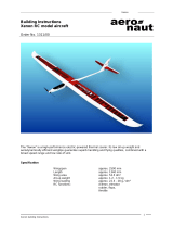
21. Installing the motor
Fix the motor to the motor bulkhead 38 using the screws
included in the power set. Install this assembly using the
screws 40, as shown in Fig. 27.
22. Installing the canopy latch catches
Fit the canopy 5 into the fuselage from the front, sliding it in
towards the wing, and only then push it down at the front. Fit
the two latch tongues 23 “dry”, and carefully position them
flush. Apply thick cyano to the serrated areas, then insert the
latch tongues into the slots in the canopy. Slide the canopy into
the fuselage, and allow the latch tongues to engage in the
latch catches 22. Immediately position the canopy accurately
on the fuselage while the glue is still wet. Wait for about one
minute before carefully opening the canopy again. Apply more
glue to the latch tongues if necessary.
Fig. 29
23. Installing the flight pack and receiver
The space for the flight battery is under the canopy, and extends
back under the wing saddle. Stick the strips of Velcro (hook-
and-loop) tape 20 / 21 in this area to secure the battery.
The speed controller fits in the side of the fuselage adjacent to
the flight pack. Install the receiver under the wing saddle, again
using the Velcro strips 20 / 21.
Fig. 30
Do not connect the battery to the speed controller unless
the transmitter is already switched on, and you are sure
that the throttle control is at the “OFF” position.
Connect the servo plugs to the receiver. Switch the transmitter
on, connect the flight battery to the speed controller, and the
controller to the receiver.
Now switch the motor on briefly so that you can check the
direction of rotation of the propeller (when checking the motor
be sure to hold the model securely, and remove any loose,
lightweight objects in front of and behind the model). If the
motor spins in the wrong direction, reverse two of the wires at
the motor - do not reverse the flight battery!
Caution: keep well clear of the propeller blades: serious injury
risk!
24. Deploying the aerial on the underside of the fuselage
The receiver aerial can be routed down and out of the
underside of the fuselage, and then deployed aft towards the
tail. You will need to pierce a hole through the fuselage floor,
working from the inside of the fuselage. Slip the aerial through
the hole from the inside, and fix it to the fuselage with a strip of
adhesive tape. If the aerial is longer (35 / 40 MHz), allow the
loose end to trail freely.
25. Setting the control surface travels
Setting the correct control surface travels is important if you
wish the model to respond to the control commands in a
balanced manner.
Up-elevator (stick back, towards you) 25 mm
Down-elevator (stick forward, away from you) 22 mm
Left rudder 25 mm
Right rudder 25 mm
Up-aileron 22 mm
Down-aileron 12 mm
The travels should always be measured at the widest part of
the control surface.
The control surface throws are not critical, and if you are unable
to set the exact stated travels using your transmitter’s
adjustment facilities, that’s no problem. If the discrepancy is
relatively great, you will need to re-connect the linkage using a
different hole at the horn or servo output arm.
If you intend to fly the model as a trainer, we recommend that
you reduce the control surface travels to about 50 - 60% of the
stated values.
26. Gilding the lily - applying the decals
The kit is supplied with a multi-colour decal sheet 2. Cut out
the individual name placards and emblems and apply them to
the model in the position shown in the kit box illustration, or in
an arrangement which you find pleasing. The decals cannot
be re-positioned once applied, so place them carefully!
27. Setting the Centre of Gravity
Like any other aircraft, the FunCub must be balanced at a
particular point in order to achieve stable flying characteristics.
Assemble your model ready to fly, and install the flight battery.
The Centre of Gravity (CG) should be at a position 80 mm aft
of the root leading edge, i.e. at the fuselage sides. Mark this
point on both sides of the fuselage.
Support the model at this position on two fingertips, and it
should balance level. If not, you can move the flight battery
forward or aft to correct the balance point. Once the correct
position is found, mark the location of the flight pack inside the
model to ensure that it is always replaced in the same position.
The CG location is not critical - 10 mm forward or aft of the
stated position presents no problems.
Fig. 31
28. Preparations for the first flight
Please wait for a day with as little breeze as possible for the
model’s initial test-flight. The evening hours are often ideal for
calm conditions.
Be sure to carry out a range check before the first flight,
using the procedure described in your RC system
instructions. If you encounter a problem, please don’t risk a
flight.
Send the whole system (including battery, switch harness and
servos) to the Service Department of your RC system
manufacturer and ask them to check it.
The first flight ...
The FunCub should always be launched exactly into any wind.
If you are a beginner to model flying we strongly recommend
that you ask an experienced model pilot to help you for the
first few flights.
29. Taking off from a hard strip
If you have access to a hard landing strip, a ground take-off is
always the safest option.
Once the model is test-flown you will be able to take off and
land from rough grass, i.e. without a mown strip - and precisely
that is the charm of this model.
30. Hand-launching
Please don’t try unpowered test-glides with this model - the
result is invariably a damaged airframe. The FunCub should
be hand-launched with the motor running at half-throttle, and
always pointing directly into wind.
Ask an experienced modeller to hand-launch your aircraft for
you.
The launcher should run forward for two or three paces, then
13
give the machine a powerful straight launch, with the wings
and fuselage level. Use the controls to hold the model in a
steady, gentle climb - remember to keep the rate of ascent
shallow and the airspeed high!
Allow the aeroplane to climb to a safe height, then adjust the
trims on the transmitter until it flies in a perfectly straight line
“hands off”. While the model is still at a safe altitude, throttle
back and try out the controls on the glide. Carry out a “dry run”
landing approach at a safe height so that you are prepared for
the real landing when the battery runs flat.
Don’t try any tight turns at first, and especially not on the landing
approach at low altitude. It is always better to land safely at
some distance from you, than to force the model back to your
feet and risk a heavy landing.
31. Safety
Safety is the First Commandment when flying any model
aircraft.
Third party insurance should be considered a basic essential.
If you join a model club suitable cover will usually be available
through the organisation. It is your personal responsibility to
ensure that your insurance is adequate. Make it your job to
keep your models and your radio control system in perfect
order at all times. Check the correct charging procedure for the
batteries you are using. Make use of all sensible safety
systems and precautions which are advised for your system.
An excellent source of practical accessories is the MULTIPLEX
main catalogue, as our products are designed and
manufactured exclusively by practising modellers for other
practising modellers.
Always fly with a responsible attitude. You may think that flying
low over other people’s heads is proof of your piloting skill;
others know better. The real expert does not need to prove
himself in such childish ways. Let other pilots know that this is
what you think too.
Always fly in such a way that you do not endanger yourself or
others. Bear in mind that even the best RC system in the world
is subject to outside interference. No matter how many years
of accident-free flying you have under your belt, you have no
idea what will happen in the next minute.
We - the MULTIPLEX team - hope you have many hours of
pleasure building and flying your new model.
MULTIPLEX Modellsport GmbH & Co. KG
Product development and maintenance
Klaus Michler
14
Parts List - FunCub
Part No. Description Material Dimensions
No. off
1 1 Building instructions
2 1 Decal sheet 500 x 880 mm
3 1 L.H. fuselage shell Moulded Elapor foam Ready made
4 1 R.H. fuselage shell Moulded Elapor foam Ready made
5 1 Canopy Moulded Elapor foam Ready made
6 1 L.H. wing panel Moulded Elapor foam Ready made
7 1 R.H. wing panel Moulded Elapor foam Ready made
8 1 Tailplane Moulded Elapor foam Ready made
9 1 Fin Moulded Elapor foam Ready made
70 1 Main undercarriage unit Spring steel, 2.5 Ø Ready made
71 2 Lightweight wheel Plastic, EPP 120 Ø, hub bore 2.6 mm
Small parts set, motor mount
20 3 Velcro tape, hook 25 x 60 mm
21 3 Velcro tape, loop 25 x 60 mm
22 2 Latch catch Inj.-moulded plastic Ready made
23 2 Latch tongue Inj.-moulded plastic Ready made
24 1 Glue-fitting horn Inj.-moulded plastic Ready made
25 4 Swivel pushrod connector Metal Ready made, 6 mm Ø
26 4 Washer Metal M2
27 4 Nut Metal M2
28 6 Socket-head grubscrew Metal M3 x 3 mm
29 1 Allen key Metal 1.5 mm A/F
30 1 Front spar joiner, “deep” Inj.-moulded plastic Ready made
31 1 Rear spar joiner, “shallow” Inj.-moulded plastic Ready made
32 2 Screw Plastic M5 x 50 mm
33 2 Wing spreader plate A Inj.-moulded plastic Ready made, M5
34 2 Wing spreader plate B Inj.-moulded plastic Ready made, M5
35 1 Glue-fitting horn, tailskid Inj.-moulded plastic Ready made
36 1 Glue-fitting tailwheel bracket Inj.-moulded plastic Ready made
37 2 Motor mount Inj.-moulded plastic Ready made
38 1 Motor bulkhead Inj.-moulded plastic Ready made
39 4 Motor bulkhead adjustment screw Metal M3 x 10 mm
40 2 Motor bulkhead mounting screw Metal M3 x 16 mm
41 8 “Twin” control surface horn Plastic Ready made
42 6 “Twin” horn bracket Plastic Ready made
43 2 Pivot barrel Metal Ready made, 6 mm Ø
44 2 Glue-fitting horn, landing flaps Inj.-moulded plastic Ready made
45 2 Pre-formed aileron pushrod (Z-bend) Metal 1 Ø x 90 mm
46 2 Pre-formed flap pushrod (Z-bend) Metal 1 Ø x 105 mm
47 1 Aero-tow mechanism Inj.-moulded plastic Ready made
48 1 Aero-tow release pushrod (Z-bend) Metal 1 Ø x 90 mm
Wire and rod set
50 2 Front tubular spar CRP tube 8 Ø x 6 x 400 mm
51 2 Rear tubular spar CRP tube 8 Ø x 6 x 100mm
52 1 Elevator pushrod (Z-bend) Metal 0.8 Ø x 510 mm
53 1 Rudder pushrod (Z-bend) Metal 0.8 Ø x 510 mm
54 1 Elevator snake outer sleeve Plastic 3/2 Ø x 480 mm
55 1 Rudder snake outer sleeve Plastic 3/2 Ø x 480 mm
56 1 Elevator snake inner sleeve Plastic 2/1 Ø x 500 mm
57 1 Rudder snake inner sleeve Plastic 2/1 Ø x 500 mm
Undercarriage set
72 4 Collet Metal 2.7 Ø / 8 x 5 mm
73 4 Socket-head grubscrew Metal M3 x 3 mm
74 1 Undercarriage bracket
Plastic Ready made
75 1 Screw Metal M3 x 12 mm
76 1 Tailwheel unit Metal 1.3 mm Ø
77 1 Lightweight tailwheel Plastic, EPP 53 Ø, hub bore 1.6 mm
78 2 Tailwheel retainer (tubular rivet) Metal rivet 2.0 Ø x 0.2 x 3 mm
15
Familiarisez-vous avec le kit d’assemblage!
Les kits d’assemblages MULTIPLEX sont soumis pendant la production à des contrôles réguliers du matériel. Nous espérons
que le contenu du kit répond à vos espérances. Nous vous prions de vérifier le contenu (suivant la liste des pièces) du kit avant
l’assemblage, car les pièces utilisées ne sont pas échangées. Dans le cas où une pièce ne serait pas conforme, nous
sommes disposés à la rectifier ou à l’échanger après contrôle. Veuillez retourner la pièce à notre unité de production sans
omettre de joindre le coupon de caisse ainsi que le formulaire de réclamation (document) dument rempli.
Nous nous réservons le droit de modifications de la forme, dimensions, technologie, matériel et contenu sans préavis. De ce
fait, nous ne prenons donc pas en compte toutes réclamations au sujet des images ou de données ne correspondantes pas
au contenu du manuel.
Attention!
Les modèles radiocommandés, surtout volants, ne sont pas des jouets au sens propre du terme. Leur assemblage et
utilisation demande des connaissances technologiques, un minimum de dextérité manuelle, de rigueur, de discipline
et de respect de la sécurité. Les erreurs et négligences, lors de la construction ou de l’utilisation, peuvent conduire à
des dégâts corporels ou matériels. Du fait que le producteur du kit n’a plus aucune influence sur l’assemblage, la
réparation et l’utilisation correcte, nous déclinons toute responsabilité concernant ces dangers.
Equipement conseillé :
Récepteur à partir de RX7 light M-Link Nr. Com. 5 5810
Ou RX-9-DR M-LINK40 MHz Nr. Com. 5 5812
Récepteur RX-7-Synth IPD 35 MHz Bande A Nr. Com. 5 5880
Ou RX-9-DR M-LINK40 MHz Nr. Com. 5 5812
Alternative 40/41 MHz Nr. Com. 5 5882
2 Servo Tiny-S (direction, profondeur) Nr. Com. 6 5121
2 Servo Nano-S UNI (aileron) Nr. Com. 6 5120
Option : encore 2 ou 3 servos Nano-S Nr. Com. 6 5120
(pour volets d’atterrissages et crochet de remorquage)
Kit de propulsion :
Kit de propulsion ‘’FunCub’’ Nr. Com. 33 2649
Avec moteur Brushless, régulateur, hélice,
Entraîneur et équipement
Accu conseillé :
Li-BATT eco 3/1-2000 (M6) Nr. Com. 15 7231
Colle :
Zacki ELAPOR® 20g VE 20 Nr. Com. 59 2727
Zacki ELAPOR® super liquide 10g VE20 Nr. Com. 59 2728
Astuce !
Kit de propulsion ‘’FunCub’’ Li-Batt powered Nr. Com. 33 3649
Comme décrit ci-dessus mais avec un accu de
propulsion Li-BATT eco 3/1-2000(M6).
Outils :
Ciseaux, cutter, pince multi, tournevis.
Données techniques :
Envergure 1400 mm
Longueur totale 980 mm
Poids en vol env. 1130g
Surface alaire 38 dm²
Charge alaire dès 30g/dm²
Fonctions RC profondeur, direction, ailerons, moteur.
Volets d’atterrissages et crochet de remorquage (option)
# 21 4243
F
16
Information importante
Ce modèle n’est pas en polystyrène™!De ce fait, n’utilisez pas de colle blanche, polyuréthane ou époxy. Ces colles ne
tiennent que superficiellement et cassent sous une contrainte trop importante. N’utilisez que des colles cyanoacrylate
/ colle rapide de viscosité moyenne, de préférence notre Zacki-ELAPOR® # 59 2727 qui est optimisé pour la mousse
type ELAPOR® et colle rapide correspondante.
Si vous utilisez notre Zacki-ELAPOR® vous pouvez vous passer d’activateur ou de Kicker. Néanmoins, si vous utilisez
d’autres colles, et que vous ne pouvez pas vous passer d’activateur, veillez utiliser se dernier dans un endroit bien
aéré voir ou de préférence à l’extérieur.
Attention lorsque vous travaillez avec une colle cyanoacrylate. Celle-ci durcie en l’espace de quelques secondes, et de
ce fait, évitez tout contacte avec les doigts ou autres parties du corps. Portez des lunettes pour protéger les yeux!
1. Avant de construire
Vérifiez le contenu de la boite avant de débuter les travaux.
Pour cela, vous pouvez vous aider de l’image Fig.1+2 et de la
liste des pièces.
2. Le fuselage
Dans un premier temps, collez les clips de fermetures 22 et
les supports moteurs 37 sur les deux parties du fuselage.
Fig. 3
3. Mise en place des servos
Mettez en place les servos pour la „direction“ et la „profondeur“
dans les moitiés de fuselage 3+4 puis collez les languettes
de fixations du servo. Fixez les câbles de commande avec du
ruban adhésif crépon, afin que les câbles et les connecteurs
ne peuvent pas provoquer des dommages et ne gênent pas
lors de l’opération de collage des deux moitiés de fuselage.
Fig. 4
4. Tringles de commandes
Préparez l’ensemble de tringle de commande 54/56 et 55/57.
Si nécessaire, ajustez la longueur des gaines extérieures et
intérieures puis engagez la corde à piano 52/53. Placez les
embouts des tringles dans le trou le plus à l’extérieur des
guignols. Veillez observer que l’embout en Z des tringles se
place dans le deuxième trou le plus à l’extérieur des palonniers.
Pour cela il est conseillé de poser les demi-fuselages sur un
support plat et de veiller à ce qu’il reste droit.
Fig. 5-6
5. Mise en place des pièces de fixations de l’aile
Clipsez les deux parties des pièces de fixations de l’aile 33+34
et collez les. Si nécessaire, utilisez une pince plate. Engagez
ces pièces de fixations dans la partie droite du demi-fuselage
et collez-les.
Fig. 7
6. Collez les deux parties du fuselage
Dans un premier temps, assemblez les deux parties du
fuselage 3/4 sans colle. Si tout se place correctement, collez
les parties du fuselage. Maintenez le fuselage en position tout
au long du séchage.
Fig. 7
7. Préparez le système de fixation de tringle
Mettez en place l’élément de fixation de tringle 25 pour la
profondeur 8 dans le trou le plus à l’extérieur du guignol 24 et
fixez l’ensemble avec la rondelle 26 et l’écrou 27. Attention:
respectez le sens de montage. Serrez avec délicatesse l’écrou,
le système de fixation de la tringle doit encore pouvoir bouger
et ensuite, sécurisez la position de l’écrou en appliquant une
goute (aiguille) de colle rapide ou du frein filet. Placez l’écrou
de serrage 28 dans l’élément de fixation 25 à l’aide de la clé
six pan 29. Collez le guignol 24 (avec les trous orientés vers
l’avant) dans la profondeur 8.
Fig. 8
8. Collage de la profondeur
Effectuez un test de placement de la profondeur sur le fuselage
et vérifiez si celle-ci se laisse correctement orientée – si
nécessaire, rectifiez. Ensuite collez et orientez directement
l’ensemble.
Fig. 9
9. Dérive avec roulette de queue
Passez la tringle de maintien de la roulette de queue 76 dans
la pièce de réception 36 et dans le guignol à coller 35 et tordez
le plus court possible le bout de la tringle à 90° comme indiqué
sur la Fig. 10. Collez le guignol 35, mais ne mettez que de la
colle CA vers le bas. Ensuite effectuez une fente d’environ 1,5
mm au dessus du guignol pour la tige de la roulette de queue.
Si nécessaire, enlevez le surplus de colle. Passez la tige 76
de la roulette de queue au dessus du guignol 35 et enfoncez
celle-ci, orientez l’ensemble et collez soigneusement le tout
avec de la colle CA. Montez le système de fixation de la tringle
de commande et sécurisez la position de l’écrou avec de la
colle ou du frein filet.
Fig. 11
Mettre la roulette de queue 77. Pour cela, placez tout d’abord
un cylindre de blocage 78 sur l’axe, puis placez la roue et le
deuxième cylindre de blocage. Sécurisez la position du cylindre
78 avec de la colle CA.
Fig. 12
10. Collage de la dérive
Pré assemblez la dérive sur le fuselage puis mettez en place
la profondeur, orientez correctement et collez l’ensemble.
Fig. 13
11. Train d’atterrissage principal
Pré assemblez le train d’atterrissage principal 70. Fixez un
cylindre de blocage
72 équipé respectivement de sa vis de
blocage six pans 73 sur la partie gauche et droite. Mettez en
place les roues 71 et les cylindres de blocages 72 également
équipés de leur vis de blocage 73. Ajustez l’ensemble pour
que les roues tournent librement.
Fig. 15
Collez le ‘’support de train’ 74 sur le fuselage. Appliquez une
pression puis coller.
Fig. 14
Clipsez le train d’atterrissage 70 et sécurisez la position avec
les vis 75.
Fig.15
17
12. Les ailes
Les demi-ailes 6/7 ne sont pas encore collées! Avant il faut
coller les longerons, pour cela engagez sans coller les
longerons 50/51 et les supports de longerons 30/31. Observez:
le support de longeron avant 30 est plus grand que celui de
derrière 31 ! Si tout correspond, collez uniquement les
longerons 50/51 et les supports 30/31 dans la partie droite de
l’aile.
Fig. 16
Maintenant, engagez les longerons dans la partie libre du
support de longeron (ne pas coller!). Glissez la partie gauche
de l’aile sur le longeron et son support, contrôlez la position.
Mettez de la colle dans l’évidement pour le longeron de la
partie gauche de l’aile et mettez en position la demi-aile.
Fig. 17
13. Libérez les volets d’atterrissages et les ailerons
Libérez le bord des ailerons sur les ailes 6 et 7 en suivant le
rainurage. Rodez le bord ‘’charnières’’ des gouvernes en les
faisant ‘’bouger‘’ plusieurs fois sans pour autant appliquer
trop de débattement – surtout ne les séparez pas! Si vous
souhaitez utiliser les volets d’atterrissages, libérez les
également de chaque côté et libérez les de l’aile. Poncez
soigneusement les zones de séparations
Fig 18/19
Le volet est positionné jointivement avec le reste de l’aile et
fixé avec du ruban adhésif. Maintenant votre volet se marie
bien avec le contour de l’aile. Dans le cas où vous ne souhaitez
pas activer les volets d’atterrissages vous pouvez couper les
bouts qui dépassent.
Fig. 20
Si vous souhaitez utiliser les volets d’atterrissages, mettez en
place six charnières Offset composées des pièces 41 et 42.
Avant de coller les guignols il faut asperger finement
d’activateur les endroits de réceptions et laisser aérer pendant
environ 60 secondes. Collez les charnières au préalablement
préparées dans les zones de réceptions des volets
d’atterrissages.
Fig. 21
Clipsez les pièces de réception des tringles de commandes
43 dans le des guignols pour les ailerons et les volets de
courbures. A l’aide de la clé six pans 29, placez la vis six pans
de blocage 28 dans la pièces de réception de tringle 43. Collez
ces guignols 41+44 dans la zone de réception des ailerons.
Fig. 22
14. Mise en place des servos des ailerons
A l’aide de votre radiocommande, placez les servos en position
‘’neutre’’. Mettez en place les palonniers de telle manière à ce
que celui-ci fasse un angle de 90° vers le côté en position
‘’neutre’’ - 1x vers la gauche et 1x vers la droite (miroité).
Adapté les zones de réceptions des parties d’ailes 6 et 7.
Pour cela placez la propulsion dans le sens de vol.
En fonction du type de servos utilisé, il est possible de devoir
adapter la zone de réception. Pour la fixation, placez une goutte
de colle à chaud ou colle rapide dans les fentes des lèvres de
fixations du servo et de l’aile, mettez de suite le servo en place
et, si nécessaire, rajoutez de la colle.
15. Mise en place des tringles de commandes des ailerons
La partie en forme de Z de la tringle de commande 45 pour les
ailerons se fixe dans le trou extérieur du palonnier et, lorsque
la gouverne est en position ‘’neutre’’, serrez la vis de blocage
28 du système de fixation du guignol.
16. Mise en place des servos des volets de courbures
A l’aide de votre radiocommande, placez les servos en position
‘’neutre’’. Mettez en place les longs palonniers sur le servo de
telle manière à ce que celui-ci fasse un angle de 70° (voir
illustration Fig. 23) - 1x vers la gauche et 1x vers la droite
(miroité), si nécessaire, découpez l’illustration.
La partie en forme de Z de la tringle de commande 46 pour les
volets se fixe à environ 23mm de l’axe de rotation du palonnier
et de l’autre côté dans le système de blocage 25. Placez les
gouvernes et les servos en position ‘’neutre’’ et bloquez la
tringle en serrant la vis de blocage 28 du système de fixation
du guignol. Fig. 24
Lorsque tout est correctement assemblé vous séparez à
nouveau les deux parties de l’aile en son centre.
17. Crochet de remorquage
Vous pouvez à tout moment équiper votre modèle du crochet
de remorquage 47. Collez celui-ci dans l’évidement de la partie
droite de l’aile. Placez le servo en position de „neutre“, puis
montez le palonnier de telle manière que, vue en direction de
vol, celui-ci pointe vers l’avant. Engagez dans le palonnier la
partie préformée et coupée à la bonne longueur de la tringle
de commande 48 du crochet de remorquage. Le servo sera
placé dans l’évidement se situant en dessous de l’aile et sera
fixé avec de la colle à chaud ou colle rapide. Fig. 25
18. Montage de contrôle
Assemblez les ailes. Les ailes sont vissées au fuselage au
travers des vis plastique 32. Grâce à la forme de l’aile du côté
fuselage, celle-ci est sécurisée et ne peut pas se déplacer.
Fig. 26
19. Kit de propulsion:
Comme kit de propulsion nous avons prévu d’utiliser notre kit
MULTIPLEX FunCub Nr. Com. 33 2649
. La consommation de
courant pour un accu type LiPo 3S LiPo et l’hélice fournie: env
.
23A
Celui-ci contient le moteur: Himax C 3516-0840, régulateur
MULTIcont BL-30 S-BEC, hélice 13x4“ et un entraîneur avec
cône.Fig.27
20. Montage du pare-feu et du support moteur
A l’aide des supports moteurs 37 et du pare-feu 38 il est
possible d’influencer le piqueur et l’anti-couple du moteur. Le
support est déjà monté asymétriquement lorsque les 4 vis de
réglages 39 sont vissés au même niveau, vous avez alors
l’anti-couple maximum mais pas de piqueur. Nous conseillons
cela comme réglage de base. Pour cela il faut regarder de
derrière sur le pare-feu.
Fig. 28
Les vis type Maden doivent dépasser comme indiqué de
l’arrière du pare-feu:
A gauche en haut: 3,0 mm
A droite en haut: 3,0 mm
A gauche en bas : 1,5 mm
A droite en bas: 1,5 mm
Les vis doivent dépasser de la valeur respective indiquée.
Un réglage fin est nécessaire après avoir effectué le premier
vol!
21. Mise en place du moteur
Fixez le moteur avec les vis de fixations 40 comprises dans le
kit de propulsion sur le pare-feu 38 comme indiqué sur la
Fig. 27.
18
6
7
8
9
5
4
3
35
51
36
29
31
30
73
23
32
71
74
38
37
45
8x41
44
52
56
54
57
53
55
48
6x 42
46
25
78
76
24
Abb. 1
Abb. 2
34
3x 20
3x 21
4x 39
2x 40
72
22
47
33
50
75
70
77
43
28
27
26
26
27
28
25
19
Abb. 3
Abb. 4
Abb. 6Abb. 5
Abb. 7
Abb. 9
Abb.10
4
22
37
4
52
56
54
54 56 52
53 57 55
4
3
27 26 24 25 28
8
8
3
4
35
36
76
Abb.8
4
3
2x 33/34
20
7
Abb. 18
Abb. 16
Abb. 14
Abb. 12
Abb. 13
Abb. 15
Abb. 17
Abb. 11
28
25
35
26
27
76
78
77
78
76
36
9
8
74
3
4
70
6
51
50
7
50
30
51
31
71
73
72
75
  • Page 1 1
  • Page 2 2
  • Page 3 3
  • Page 4 4
  • Page 5 5
  • Page 6 6
  • Page 7 7
  • Page 8 8
  • Page 9 9
  • Page 10 10
  • Page 11 11
  • Page 12 12
  • Page 13 13
  • Page 14 14
  • Page 15 15
  • Page 16 16
  • Page 17 17
  • Page 18 18
  • Page 19 19
  • Page 20 20
  • Page 21 21
  • Page 22 22
  • Page 23 23
  • Page 24 24
  • Page 25 25
  • Page 26 26
  • Page 27 27
  • Page 28 28
  • Page 29 29
  • Page 30 30
  • Page 31 31
  • Page 32 32
  • Page 33 33
  • Page 34 34
  • Page 35 35
  • Page 36 36
  • Page 37 37
  • Page 38 38
  • Page 39 39
  • Page 40 40

MULTIPLEX Funcub Owner's manual

Category
Remote controlled toys
Type
Owner's manual
This manual is also suitable for

Ask a question and I''ll find the answer in the document

Finding information in a document is now easier with AI