
ABB machinery drives
Hardware manual
ACS850-04 drive modules (0.37 to 45 kW, 0.5 to 60 hp)

List of related manuals
You can find manuals and other product documents in PDF format on the Internet. See section
Document library on the Internet on the inside of the back cover. For manuals not available in the
Document library, contact your local ABB representative.
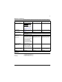
Drive hardware manuals and guides Code (English)
ACS850-04 drive modules (0.37 to 45 kW, 0.5 to 60 hp) hardware manual 3AUA0000045496
ACS850-04 drive modules (0.37 to 45 kW, 0.5 to 60 hp) quick installation guide 3AUA0000045495
Safe torque off function for ACSM1, ACS850 and ACQ810 drives application
guide
3AFE68929814
Drive firmware manuals and guides
ACS850 standard control program firmware manual 3AUA0000045497
ACS850 standard control program quick start-up guide 3AUA0000045498
ACS850 crane control program supplement (to std ctrl prg) 3AUA0000081708
ACS850-04 drives with SynRM motors (option +N7502) supplement 3AUA0000123521
Option manuals and guides
Common DC configuration for ACS850-04 drives application guide 3AUA0000073108
ATEX-certified Safe disconnection function for ACS850 drives (+Q971)
application guide
3AUA0000074343
Application programming for ACS850 and ACQ810 drives application guide 3AUA0000078664
Manuals and quick guides for I/O extension modules, fieldbus adapters, etc.
ACS850-04 manuals

ACS850-04 drive modules
0.37 to 45 kW, 0.5 to 60 hp
Hardware manual
3AUA0000045496 Rev F
EN
EFFECTIVE: 2013-02-28
2013 ABB Oy. All Rights Reserved.


Safety instructions
5
Safety instructions
What this chapter contains
This chapter contains safety instructions which you must follow when installing,
operating and servicing the drive. If ignored, physical injury or death may follow, or
damage may occur to the drive, the motor, or driven equipment. Read the safety
instructions before you work on the unit.
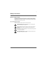
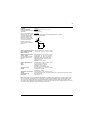
Use of warnings and notes
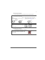
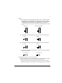
There are four types of safety instructions used in this manual:
Electricity warning warns of high voltage which can cause physical
injury and/or damage to the equipment.
General warning warns about conditions, other than those caused by
electricity, which can result in physical injury and/or damage to the
equipment.
Electrostatic discharge warning warns of electrostatic discharge which
can damage the equipment.
Hot surface warning warns of component surfaces that may become
hot enough to cause burns if touched.

Safety instructions
6
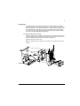
Installation and maintenance work
These warnings are intended for all who work on the drive, motor cable or motor.
WARNING! Ignoring the following instructions can cause physical injury or death, or
damage to the equipment.
Only qualified electricians are allowed to install and maintain the drive.
•
Never work on the drive, the motor cable or the motor when input power is
applied. After disconnecting the input power, always wait for 5 minutes to let the
intermediate circuit capacitors discharge before you start working on the drive,
the motor or the motor cable.
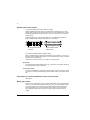
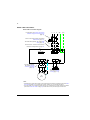
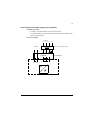
Always ensure by measuring with a multimeter (impedance at least 1 Mohm)
that:
1. There is no voltage between the drive input phases U1, V1 and W1 and the
ground.
2. There is no voltage between terminals UDC+ and UDC– and the ground.
3. There is no voltage between terminals R+ and R– and the ground.
•
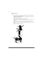
Drives controlling a permanent magnet motor: A rotating permanent magnet
motor feeds power to the drive causing the drive to become live even when it is
stopped and the supply power switched off. Before maintenance work on the
drive,
– disconnect the motor from the drive by using a safety switch
– prevent the start-up of any other motors in the same mechanical system
– lock the motor shaft
– measure that the motor is in fact de-energised, then connect the U2, V2 and
W2 terminals of the drive to each other and to the PE.
•
Do not work on the control cables when power is applied to the drive or to the
external control circuits. Externally supplied control circuits may carry
dangerous voltages even when the input power of the drive is switched off.
•
Do not make any insulation or voltage withstand tests on the drive.
•
If a drive whose varistors or EMC filters are not disconnected is installed on an
IT power system (an ungrounded power system or a high resistance grounded
[over 30 ohms] power system), the drive will be connected to earth potential
through the varistors/filters. This may cause danger or damage the drive.
•
If a drive whose varistors or EMC filters are not disconnected is installed on a
corner-grounded TN system, the drive will be damaged.
Notes:
•
Even when the motor is stopped, dangerous voltages are present at the power
circuit terminals U1, V1, W1 and U2, V2, W2, and UDC+, UDC–, R+, R–.
•
Depending on the external wiring, dangerous voltages (115 V, 220 V or 230 V)
may be present on the terminals of the relay outputs of the drive.

Safety instructions
7
•
The drive supports the Safe torque off function. See page 46.
•
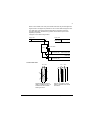
Standard EN 61800-5-1 (section 4.3.5.5.2.) requires that as the normal touch
current of the drive is higher than 3.5 mA AC or 10 mA DC, you must use a
fixed protective earth connection. In addition,
– install a second protective earthing conductor of the same cross-sectional
area as the original protective earthing conductor, or
– install a protective earthing conductor with a cross-section of at least 10 mm
2
Cu or 16 mm
2
Al, or
– install a device which automatically disconnects the supply if the protective
earthing conductor breaks.
WARNING! Ignoring the following instructions can cause physical injury or death, or
damage to the equipment.
•
The drive is not field repairable. Never attempt to repair a malfunctioning drive;
contact your local ABB representative or Authorized Service Center for
replacement.
•
Make sure that dust from drilling does not enter the drive during the installation.
Electrically conductive dust inside the drive may cause damage or lead to
malfunction.
•
Ensure sufficient cooling.
WARNING! The printed circuit boards contain components sensitive to electrostatic
discharge. Wear a grounding wrist band when handling the boards. Do not touch
the boards unnecessarily.

Safety instructions
8
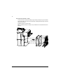
Start-up and operation
These warnings are intended for all who plan the operation of the drive, start up or
operate the drive.
WARNING! Ignoring the following instructions can cause physical injury or death,
or damage to the equipment.
•
Before adjusting the drive and putting it into service, make sure that the motor
and all driven equipment are suitable for operation throughout the speed range
provided by the drive. The drive can be adjusted to operate the motor at
speeds above and below the speed provided by connecting the motor directly
to the power line.
•
Do not activate automatic fault reset functions if dangerous situations can
occur. When activated, these functions will reset the drive and resume
operation after a fault.
•
Do not control the motor with an AC contactor or disconnecting device
(disconnecting means); instead, use the control panel or external commands
via the I/O board of the drive or a fieldbus adapter. The maximum allowed
number of charging cycles of the DC capacitors (i.e. power-ups by applying
power) is one per two minutes. The maximum total number of chargings is
100000 for frame sizes A and B, 50000 for frame sizes C and D.
•
Drives controlling a permanent magnet motor: Do not run the motor over the
rated speed. Motor overspeed leads to overvoltage which may permanently
damage the drive.
Notes:
•
If an external source for start command is selected and it is ON, the drive will
start immediately after an input voltage break or a fault reset unless the drive is
configured for 3-wire (pulse) start/stop.
•
When the control location is not set to local, the stop key on the control panel
will not stop the drive.
WARNING! The surfaces of drive system components (such as the mains choke
and brake resistor, if present) become hot when the system is in use.

Table of contents
9
Table of contents
List of related manuals . . . . . . . . . . . . . . . . . . . . . . . . . . . . . . . . . . . . . . . . . . . . . . . . . . . . . . . . . . . 2
Safety instructions
What this chapter contains . . . . . . . . . . . . . . . . . . . . . . . . . . . . . . . . . . . . . . . . . . . . . . . . . . . . . . . . 5
Use of warnings and notes . . . . . . . . . . . . . . . . . . . . . . . . . . . . . . . . . . . . . . . . . . . . . . . . . . . . . . . . 5
Installation and maintenance work . . . . . . . . . . . . . . . . . . . . . . . . . . . . . . . . . . . . . . . . . . . . . . . . . . 6
Start-up and operation . . . . . . . . . . . . . . . . . . . . . . . . . . . . . . . . . . . . . . . . . . . . . . . . . . . . . . . . . . . . 8
Table of contents
Introduction to this manual
What this chapter contains . . . . . . . . . . . . . . . . . . . . . . . . . . . . . . . . . . . . . . . . . . . . . . . . . . . . . . . 15
Compatibility . . . . . . . . . . . . . . . . . . . . . . . . . . . . . . . . . . . . . . . . . . . . . . . . . . . . . . . . . . . . . . . . . . 15
Intended audience . . . . . . . . . . . . . . . . . . . . . . . . . . . . . . . . . . . . . . . . . . . . . . . . . . . . . . . . . . . . . . 15
Categorization according to the frame size . . . . . . . . . . . . . . . . . . . . . . . . . . . . . . . . . . . . . . . . . . . 15
Categorization according to the + code . . . . . . . . . . . . . . . . . . . . . . . . . . . . . . . . . . . . . . . . . . . . . . 15
Contents . . . . . . . . . . . . . . . . . . . . . . . . . . . . . . . . . . . . . . . . . . . . . . . . . . . . . . . . . . . . . . . . . . . . . 15
Installation and commissioning flowchart . . . . . . . . . . . . . . . . . . . . . . . . . . . . . . . . . . . . . . . . . . . . 17
Terms and abbreviations . . . . . . . . . . . . . . . . . . . . . . . . . . . . . . . . . . . . . . . . . . . . . . . . . . . . . . . . . 19
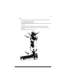
Operation principle and hardware description
What this chapter contains . . . . . . . . . . . . . . . . . . . . . . . . . . . . . . . . . . . . . . . . . . . . . . . . . . . . . . . 21
Operation principle . . . . . . . . . . . . . . . . . . . . . . . . . . . . . . . . . . . . . . . . . . . . . . . . . . . . . . . . . . . . . 21
Main circuit . . . . . . . . . . . . . . . . . . . . . . . . . . . . . . . . . . . . . . . . . . . . . . . . . . . . . . . . . . . . . . . 21
Motor control . . . . . . . . . . . . . . . . . . . . . . . . . . . . . . . . . . . . . . . . . . . . . . . . . . . . . . . . . . . . . 22
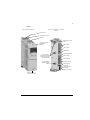
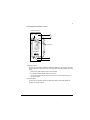
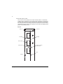
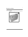
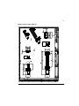
Product overview . . . . . . . . . . . . . . . . . . . . . . . . . . . . . . . . . . . . . . . . . . . . . . . . . . . . . . . . . . . . . . . 22
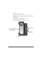
Layout . . . . . . . . . . . . . . . . . . . . . . . . . . . . . . . . . . . . . . . . . . . . . . . . . . . . . . . . . . . . . . . . . . 23
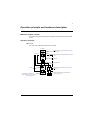
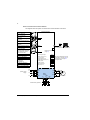
Power connections and control interfaces . . . . . . . . . . . . . . . . . . . . . . . . . . . . . . . . . . . . . . . 24
Type designation label . . . . . . . . . . . . . . . . . . . . . . . . . . . . . . . . . . . . . . . . . . . . . . . . . . . . . . . . . . 25
Type designation key . . . . . . . . . . . . . . . . . . . . . . . . . . . . . . . . . . . . . . . . . . . . . . . . . . . . . . . . . . . 26
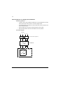
Planning the cabinet assembly
What this chapter contains . . . . . . . . . . . . . . . . . . . . . . . . . . . . . . . . . . . . . . . . . . . . . . . . . . . . . . . 29
Cabinet construction . . . . . . . . . . . . . . . . . . . . . . . . . . . . . . . . . . . . . . . . . . . . . . . . . . . . . . . . . . . . 29
Disposition of the devices . . . . . . . . . . . . . . . . . . . . . . . . . . . . . . . . . . . . . . . . . . . . . . . . . . . 29
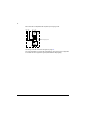
Grounding of mounting structures . . . . . . . . . . . . . . . . . . . . . . . . . . . . . . . . . . . . . . . . . . . . . 29
Main dimensions and free space requirements . . . . . . . . . . . . . . . . . . . . . . . . . . . . . . . . . . . . . . . . 30
Cooling and degrees of protection . . . . . . . . . . . . . . . . . . . . . . . . . . . . . . . . . . . . . . . . . . . . . . . . . 31
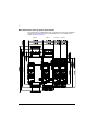
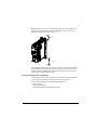
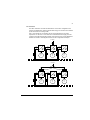
Preventing the recirculation of hot air . . . . . . . . . . . . . . . . . . . . . . . . . . . . . . . . . . . . . . . . . . 33
Outside the cabinet . . . . . . . . . . . . . . . . . . . . . . . . . . . . . . . . . . . . . . . . . . . . . . . . . . . . 33
Inside the cabinet . . . . . . . . . . . . . . . . . . . . . . . . . . . . . . . . . . . . . . . . . . . . . . . . . . . . . 33

Table of contents
10
Cabinets with multiple modules . . . . . . . . . . . . . . . . . . . . . . . . . . . . . . . . . . . . . . . . . . .34
Cabinet heaters . . . . . . . . . . . . . . . . . . . . . . . . . . . . . . . . . . . . . . . . . . . . . . . . . . . . . . . . . . . . . . . .35
Mechanical installation
Contents of the package . . . . . . . . . . . . . . . . . . . . . . . . . . . . . . . . . . . . . . . . . . . . . . . . . . . . . . . . .37
Delivery check and drive module identification . . . . . . . . . . . . . . . . . . . . . . . . . . . . . . . . . . . .39
Before installation . . . . . . . . . . . . . . . . . . . . . . . . . . . . . . . . . . . . . . . . . . . . . . . . . . . . . . . . . . . . . . .39
Requirements for the installation site . . . . . . . . . . . . . . . . . . . . . . . . . . . . . . . . . . . . . . . . . . .39
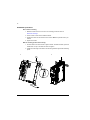
Installation procedure . . . . . . . . . . . . . . . . . . . . . . . . . . . . . . . . . . . . . . . . . . . . . . . . . . . . . . . . . . . .40
Direct surface mounting . . . . . . . . . . . . . . . . . . . . . . . . . . . . . . . . . . . . . . . . . . . . . . . . . . . . .40
DIN rail mounting (Frames A and B only) . . . . . . . . . . . . . . . . . . . . . . . . . . . . . . . . . . . . . . . .40
Mains choke installation . . . . . . . . . . . . . . . . . . . . . . . . . . . . . . . . . . . . . . . . . . . . . . . . . . . . .41
EMC filter installation . . . . . . . . . . . . . . . . . . . . . . . . . . . . . . . . . . . . . . . . . . . . . . . . . . . . . . .41
Brake resistor installation . . . . . . . . . . . . . . . . . . . . . . . . . . . . . . . . . . . . . . . . . . . . . . . . . . . .41
Planning the electrical installation
What this chapter contains . . . . . . . . . . . . . . . . . . . . . . . . . . . . . . . . . . . . . . . . . . . . . . . . . . . . . . . .43
Motor selection . . . . . . . . . . . . . . . . . . . . . . . . . . . . . . . . . . . . . . . . . . . . . . . . . . . . . . . . . . . . . . . . .43
Supply disconnecting device . . . . . . . . . . . . . . . . . . . . . . . . . . . . . . . . . . . . . . . . . . . . . . . . . . . . . .43
Europe . . . . . . . . . . . . . . . . . . . . . . . . . . . . . . . . . . . . . . . . . . . . . . . . . . . . . . . . . . . . . . . . . . .43
Other regions . . . . . . . . . . . . . . . . . . . . . . . . . . . . . . . . . . . . . . . . . . . . . . . . . . . . . . . . . . . . .43
Thermal overload and short circuit protection . . . . . . . . . . . . . . . . . . . . . . . . . . . . . . . . . . . . . . . . .44
Thermal overload protection . . . . . . . . . . . . . . . . . . . . . . . . . . . . . . . . . . . . . . . . . . . . . . . . . .44
Protection against short-circuit in the motor cable . . . . . . . . . . . . . . . . . . . . . . . . . . . . . . . . .44
Protection against short-circuit in the supply cable or the drive . . . . . . . . . . . . . . . . . . . . . . .44
Operating time of the fuses and circuit breakers . . . . . . . . . . . . . . . . . . . . . . . . . . . . .44
Circuit breakers . . . . . . . . . . . . . . . . . . . . . . . . . . . . . . . . . . . . . . . . . . . . . . . . . . . . . . .44
Motor thermal protection . . . . . . . . . . . . . . . . . . . . . . . . . . . . . . . . . . . . . . . . . . . . . . . . . . . . .45
Ground fault protection . . . . . . . . . . . . . . . . . . . . . . . . . . . . . . . . . . . . . . . . . . . . . . . . . . . . . . . . . . .45
Emergency stop devices . . . . . . . . . . . . . . . . . . . . . . . . . . . . . . . . . . . . . . . . . . . . . . . . . . . . . . . . .45
Safe torque off function . . . . . . . . . . . . . . . . . . . . . . . . . . . . . . . . . . . . . . . . . . . . . . . . . . . . . . . . . .46
Selecting the power cables . . . . . . . . . . . . . . . . . . . . . . . . . . . . . . . . . . . . . . . . . . . . . . . . . . . . . . .46
General rules . . . . . . . . . . . . . . . . . . . . . . . . . . . . . . . . . . . . . . . . . . . . . . . . . . . . . . . . . . . . . .46
Alternative power cable types . . . . . . . . . . . . . . . . . . . . . . . . . . . . . . . . . . . . . . . . . . . . . . . . .47
Not allowed power cable type . . . . . . . . . . . . . . . . . . . . . . . . . . . . . . . . . . . . . . . . . . . . . . . . .47
Motor cable shield . . . . . . . . . . . . . . . . . . . . . . . . . . . . . . . . . . . . . . . . . . . . . . . . . . . . . . . . . .48
Protecting the relay output contacts and attenuating disturbances in case of inductive loads . . . . .48
Considering the PELV requirements at sites above 2000 m (6562 ft) . . . . . . . . . . . . . . . . . . . . . . .49
Selecting the control cables . . . . . . . . . . . . . . . . . . . . . . . . . . . . . . . . . . . . . . . . . . . . . . . . . . . . . . .50
Relay cable . . . . . . . . . . . . . . . . . . . . . . . . . . . . . . . . . . . . . . . . . . . . . . . . . . . . . . . . . . . . . . .50
Control panel cable . . . . . . . . . . . . . . . . . . . . . . . . . . . . . . . . . . . . . . . . . . . . . . . . . . . . . . . . .50
Connection of a motor temperature sensor to the drive I/O . . . . . . . . . . . . . . . . . . . . . . . . . . . . . . .50
Routing the cables . . . . . . . . . . . . . . . . . . . . . . . . . . . . . . . . . . . . . . . . . . . . . . . . . . . . . . . . . . . . . .50
Control cable ducts . . . . . . . . . . . . . . . . . . . . . . . . . . . . . . . . . . . . . . . . . . . . . . . . . . . . . . . . .51

Table of contents
11
Electrical installation
What this chapter contains . . . . . . . . . . . . . . . . . . . . . . . . . . . . . . . . . . . . . . . . . . . . . . . . . . . . . . . 53
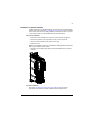
Removing the cover assembly . . . . . . . . . . . . . . . . . . . . . . . . . . . . . . . . . . . . . . . . . . . . . . . . . . . . 53
Checking the insulation of the assembly . . . . . . . . . . . . . . . . . . . . . . . . . . . . . . . . . . . . . . . . . . . . . 55
Drive . . . . . . . . . . . . . . . . . . . . . . . . . . . . . . . . . . . . . . . . . . . . . . . . . . . . . . . . . . . . . . . . . . . . 55
Supply cable . . . . . . . . . . . . . . . . . . . . . . . . . . . . . . . . . . . . . . . . . . . . . . . . . . . . . . . . . . . . . 55
Motor and motor cable . . . . . . . . . . . . . . . . . . . . . . . . . . . . . . . . . . . . . . . . . . . . . . . . . . . . . . 55
Brake resistor assembly . . . . . . . . . . . . . . . . . . . . . . . . . . . . . . . . . . . . . . . . . . . . . . . . . . . . . 55
Power cable connection . . . . . . . . . . . . . . . . . . . . . . . . . . . . . . . . . . . . . . . . . . . . . . . . . . . . . . . . . 56
Power cable connection diagram . . . . . . . . . . . . . . . . . . . . . . . . . . . . . . . . . . . . . . . . . . . . . . 56
Procedure . . . . . . . . . . . . . . . . . . . . . . . . . . . . . . . . . . . . . . . . . . . . . . . . . . . . . . . . . . . . . . . 57
Grounding the motor cable shield at the motor end . . . . . . . . . . . . . . . . . . . . . . . . . . . 58
Installation of power cable clamp plates . . . . . . . . . . . . . . . . . . . . . . . . . . . . . . . . . . . . 59
Power cable connection – frame size A . . . . . . . . . . . . . . . . . . . . . . . . . . . . . . . . . . . . 60
Power cable connection – frame size B . . . . . . . . . . . . . . . . . . . . . . . . . . . . . . . . . . . . 61
Power cable connection – frame sizes C and D (connector covers removed) . . . . . . . 62
DC connection . . . . . . . . . . . . . . . . . . . . . . . . . . . . . . . . . . . . . . . . . . . . . . . . . . . . . . . . . . . . 63
Installation of optional modules . . . . . . . . . . . . . . . . . . . . . . . . . . . . . . . . . . . . . . . . . . . . . . . . . . . . 65
Mechanical installation . . . . . . . . . . . . . . . . . . . . . . . . . . . . . . . . . . . . . . . . . . . . . . . . . . . . . . 65
Electrical installation . . . . . . . . . . . . . . . . . . . . . . . . . . . . . . . . . . . . . . . . . . . . . . . . . . . . . . . 65
Connecting the control cables . . . . . . . . . . . . . . . . . . . . . . . . . . . . . . . . . . . . . . . . . . . . . . . . . . . . . 66
Control connections to the JCU control unit . . . . . . . . . . . . . . . . . . . . . . . . . . . . . . . . . . . . . . 66
Jumpers . . . . . . . . . . . . . . . . . . . . . . . . . . . . . . . . . . . . . . . . . . . . . . . . . . . . . . . . . . . . 67
External power supply for the control unit (XPOW) . . . . . . . . . . . . . . . . . . . . . . . . . . . 67
DI6 (XDI:6) as a thermistor input . . . . . . . . . . . . . . . . . . . . . . . . . . . . . . . . . . . . . . . . . 68
Drive-to-drive link (XD2D) . . . . . . . . . . . . . . . . . . . . . . . . . . . . . . . . . . . . . . . . . . . . . . . 69
Safe torque off (XSTO) . . . . . . . . . . . . . . . . . . . . . . . . . . . . . . . . . . . . . . . . . . . . . . . . . 70
Grounding and routing the control cables . . . . . . . . . . . . . . . . . . . . . . . . . . . . . . . . . . . . . . . 70
Installation checklist
What this chapter contains . . . . . . . . . . . . . . . . . . . . . . . . . . . . . . . . . . . . . . . . . . . . . . . . . . . . . . . 73
Checklist . . . . . . . . . . . . . . . . . . . . . . . . . . . . . . . . . . . . . . . . . . . . . . . . . . . . . . . . . . . . . . . . . . . . . 73
Start-up
What this chapter contains . . . . . . . . . . . . . . . . . . . . . . . . . . . . . . . . . . . . . . . . . . . . . . . . . . . . . . . 75
Start-up procedure . . . . . . . . . . . . . . . . . . . . . . . . . . . . . . . . . . . . . . . . . . . . . . . . . . . . . . . . . . . . . 75
Maintenance
What this chapter contains . . . . . . . . . . . . . . . . . . . . . . . . . . . . . . . . . . . . . . . . . . . . . . . . . . . . . . . 77
Safety . . . . . . . . . . . . . . . . . . . . . . . . . . . . . . . . . . . . . . . . . . . . . . . . . . . . . . . . . . . . . . . . . . . . . . . 77
Maintenance intervals . . . . . . . . . . . . . . . . . . . . . . . . . . . . . . . . . . . . . . . . . . . . . . . . . . . . . . . . . . . 77
Heatsink . . . . . . . . . . . . . . . . . . . . . . . . . . . . . . . . . . . . . . . . . . . . . . . . . . . . . . . . . . . . . . . . . . . . . 78
Cooling fan . . . . . . . . . . . . . . . . . . . . . . . . . . . . . . . . . . . . . . . . . . . . . . . . . . . . . . . . . . . . . . . . . . . 79
Fan replacement (Frames A and B) . . . . . . . . . . . . . . . . . . . . . . . . . . . . . . . . . . . . . . . . . . . . 79
Fan replacement (Frames C and D) . . . . . . . . . . . . . . . . . . . . . . . . . . . . . . . . . . . . . . . . . . . 80
Reforming the capacitors . . . . . . . . . . . . . . . . . . . . . . . . . . . . . . . . . . . . . . . . . . . . . . . . . . . . . . . . 81

Table of contents
12
Other maintenance actions . . . . . . . . . . . . . . . . . . . . . . . . . . . . . . . . . . . . . . . . . . . . . . . . . . . . . . .81
Transferring the memory unit to a new drive module . . . . . . . . . . . . . . . . . . . . . . . . . . . . . . .81
Technical data
What this chapter contains . . . . . . . . . . . . . . . . . . . . . . . . . . . . . . . . . . . . . . . . . . . . . . . . . . . . . . . .83
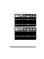
Ratings . . . . . . . . . . . . . . . . . . . . . . . . . . . . . . . . . . . . . . . . . . . . . . . . . . . . . . . . . . . . . . . . . . . . . . .83
Nominal ratings with 230 V AC supply . . . . . . . . . . . . . . . . . . . . . . . . . . . . . . . . . . . . . . . . . .83
Nominal ratings with 400 V AC supply . . . . . . . . . . . . . . . . . . . . . . . . . . . . . . . . . . . . . . . . . .84
Nominal ratings with 460 V AC supply . . . . . . . . . . . . . . . . . . . . . . . . . . . . . . . . . . . . . . . . . .84
Nominal ratings with 500 V AC supply . . . . . . . . . . . . . . . . . . . . . . . . . . . . . . . . . . . . . . . . . .85
Symbols . . . . . . . . . . . . . . . . . . . . . . . . . . . . . . . . . . . . . . . . . . . . . . . . . . . . . . . . . . . . . . . . .85
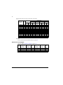
Derating . . . . . . . . . . . . . . . . . . . . . . . . . . . . . . . . . . . . . . . . . . . . . . . . . . . . . . . . . . . . . . . . . . . . . .85
Ambient temperature derating . . . . . . . . . . . . . . . . . . . . . . . . . . . . . . . . . . . . . . . . . . . . . . . . .86
Altitude derating . . . . . . . . . . . . . . . . . . . . . . . . . . . . . . . . . . . . . . . . . . . . . . . . . . . . . . . . . . .86
Low motor noise derating . . . . . . . . . . . . . . . . . . . . . . . . . . . . . . . . . . . . . . . . . . . . . . . . . . . .86
Deratings with 230 V AC supply in low motor noise mode . . . . . . . . . . . . . . . . . . . . . .86
Deratings with 400 V AC supply in low motor noise mode . . . . . . . . . . . . . . . . . . . . . .87
Deratings with 460 V AC supply in low motor noise mode . . . . . . . . . . . . . . . . . . . . . .87
Deratings with 500 V AC supply in low motor noise mode . . . . . . . . . . . . . . . . . . . . . .88
Symbols . . . . . . . . . . . . . . . . . . . . . . . . . . . . . . . . . . . . . . . . . . . . . . . . . . . . . . . . . . . . .88
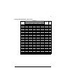
Dimensions and weights . . . . . . . . . . . . . . . . . . . . . . . . . . . . . . . . . . . . . . . . . . . . . . . . . . . . . . . . .88
Cooling characteristics, noise levels . . . . . . . . . . . . . . . . . . . . . . . . . . . . . . . . . . . . . . . . . . . . . . . .89
Supply cable fuses . . . . . . . . . . . . . . . . . . . . . . . . . . . . . . . . . . . . . . . . . . . . . . . . . . . . . . . . . . . . . .90
AC input (supply) connection . . . . . . . . . . . . . . . . . . . . . . . . . . . . . . . . . . . . . . . . . . . . . . . . . . . . . .91
DC connection . . . . . . . . . . . . . . . . . . . . . . . . . . . . . . . . . . . . . . . . . . . . . . . . . . . . . . . . . . . . . . . . .91
Motor connection . . . . . . . . . . . . . . . . . . . . . . . . . . . . . . . . . . . . . . . . . . . . . . . . . . . . . . . . . . . . . . .92
JCU control unit . . . . . . . . . . . . . . . . . . . . . . . . . . . . . . . . . . . . . . . . . . . . . . . . . . . . . . . . . . . . . . . .92
Efficiency . . . . . . . . . . . . . . . . . . . . . . . . . . . . . . . . . . . . . . . . . . . . . . . . . . . . . . . . . . . . . . . . . . . . .94
Cooling . . . . . . . . . . . . . . . . . . . . . . . . . . . . . . . . . . . . . . . . . . . . . . . . . . . . . . . . . . . . . . . . . . . . . . .94
Degree of protection . . . . . . . . . . . . . . . . . . . . . . . . . . . . . . . . . . . . . . . . . . . . . . . . . . . . . . . . . . . . .94
Ambient conditions . . . . . . . . . . . . . . . . . . . . . . . . . . . . . . . . . . . . . . . . . . . . . . . . . . . . . . . . . . . . . .95
Materials . . . . . . . . . . . . . . . . . . . . . . . . . . . . . . . . . . . . . . . . . . . . . . . . . . . . . . . . . . . . . . . . . . . . . .95
Applicable standards . . . . . . . . . . . . . . . . . . . . . . . . . . . . . . . . . . . . . . . . . . . . . . . . . . . . . . . . . . . .96
CE marking . . . . . . . . . . . . . . . . . . . . . . . . . . . . . . . . . . . . . . . . . . . . . . . . . . . . . . . . . . . . . . . . . . . .97
Compliance with the European Low Voltage Directive . . . . . . . . . . . . . . . . . . . . . . . . . . . . . .97
Compliance with the European EMC Directive . . . . . . . . . . . . . . . . . . . . . . . . . . . . . . . . . . . .97
Compliance with the Machinery Directive . . . . . . . . . . . . . . . . . . . . . . . . . . . . . . . . . . . . . . . .97
Compliance with EN 61800-3:2004 . . . . . . . . . . . . . . . . . . . . . . . . . . . . . . . . . . . . . . . . . . . . . . . . .98
Definitions . . . . . . . . . . . . . . . . . . . . . . . . . . . . . . . . . . . . . . . . . . . . . . . . . . . . . . . . . . . . . . . .98
First environment (drive of category C2) . . . . . . . . . . . . . . . . . . . . . . . . . . . . . . . . . . . . . . . . .98
Second environment (drive of category C3) . . . . . . . . . . . . . . . . . . . . . . . . . . . . . . . . . . . . . .99
Second environment (drive of category C4) . . . . . . . . . . . . . . . . . . . . . . . . . . . . . . . . . . . . . .99
C-Tick marking . . . . . . . . . . . . . . . . . . . . . . . . . . . . . . . . . . . . . . . . . . . . . . . . . . . . . . . . . . . . . . . . .99
UL marking . . . . . . . . . . . . . . . . . . . . . . . . . . . . . . . . . . . . . . . . . . . . . . . . . . . . . . . . . . . . . . . . . . .100
UL checklist . . . . . . . . . . . . . . . . . . . . . . . . . . . . . . . . . . . . . . . . . . . . . . . . . . . . . . . . . . . . . .100
Mains chokes
What this chapter contains . . . . . . . . . . . . . . . . . . . . . . . . . . . . . . . . . . . . . . . . . . . . . . . . . . . . . . .101

Table of contents
13
When is a mains choke required? . . . . . . . . . . . . . . . . . . . . . . . . . . . . . . . . . . . . . . . . . . . . . . . . . 101
Selection table . . . . . . . . . . . . . . . . . . . . . . . . . . . . . . . . . . . . . . . . . . . . . . . . . . . . . . . . . . . . . . . . 101
Installation guidelines . . . . . . . . . . . . . . . . . . . . . . . . . . . . . . . . . . . . . . . . . . . . . . . . . . . . . . . . . . 102
Connection diagram . . . . . . . . . . . . . . . . . . . . . . . . . . . . . . . . . . . . . . . . . . . . . . . . . . . . . . . 102
EMC filters
What this chapter contains . . . . . . . . . . . . . . . . . . . . . . . . . . . . . . . . . . . . . . . . . . . . . . . . . . . . . . 103
When is an EMC filter required? . . . . . . . . . . . . . . . . . . . . . . . . . . . . . . . . . . . . . . . . . . . . . . . . . . 103
Selection table . . . . . . . . . . . . . . . . . . . . . . . . . . . . . . . . . . . . . . . . . . . . . . . . . . . . . . . . . . . . . . . . 104
JFI-A1/JFI-B1 (Frame A/B, category C3) installation . . . . . . . . . . . . . . . . . . . . . . . . . . . . . . . . . . 105
Installation guidelines . . . . . . . . . . . . . . . . . . . . . . . . . . . . . . . . . . . . . . . . . . . . . . . . . . . . . . 105
Connection diagram . . . . . . . . . . . . . . . . . . . . . . . . . . . . . . . . . . . . . . . . . . . . . . . . . . . . . . . 105
Mounting procedures . . . . . . . . . . . . . . . . . . . . . . . . . . . . . . . . . . . . . . . . . . . . . . . . . . . . . . 106
JFI-A1 . . . . . . . . . . . . . . . . . . . . . . . . . . . . . . . . . . . . . . . . . . . . . . . . . . . . . . . . . . . . . 106
JFI-B1 . . . . . . . . . . . . . . . . . . . . . . . . . . . . . . . . . . . . . . . . . . . . . . . . . . . . . . . . . . . . . 107
JFI-0x (Frames A…D, category C2) installation . . . . . . . . . . . . . . . . . . . . . . . . . . . . . . . . . . . . . . 108
Installation guidelines . . . . . . . . . . . . . . . . . . . . . . . . . . . . . . . . . . . . . . . . . . . . . . . . . . . . . . 108
Connection diagram . . . . . . . . . . . . . . . . . . . . . . . . . . . . . . . . . . . . . . . . . . . . . . . . . . . . . . . 108
du/dt and common mode filtering
What this chapter contains . . . . . . . . . . . . . . . . . . . . . . . . . . . . . . . . . . . . . . . . . . . . . . . . . . . . . . 109
When is du/dt or common mode filtering required? . . . . . . . . . . . . . . . . . . . . . . . . . . . . . . . . . . . . 109
Additional requirements for ABB motors of types other than M2_, M3_, M4_, HX_
and AM_ . . . . . . . . . . . . . . . . . . . . . . . . . . . . . . . . . . . . . . . . . . . . . . . . . . . . . . . . . . . . . . . . 111
Additional requirements for the braking applications . . . . . . . . . . . . . . . . . . . . . . . . . . . . . . 111
Filter types . . . . . . . . . . . . . . . . . . . . . . . . . . . . . . . . . . . . . . . . . . . . . . . . . . . . . . . . . . . . . . . . . . . 111
du/dt filters . . . . . . . . . . . . . . . . . . . . . . . . . . . . . . . . . . . . . . . . . . . . . . . . . . . . . . . . . . . . . . 111
Common mode filters . . . . . . . . . . . . . . . . . . . . . . . . . . . . . . . . . . . . . . . . . . . . . . . . . . . . . . 111
Technical data . . . . . . . . . . . . . . . . . . . . . . . . . . . . . . . . . . . . . . . . . . . . . . . . . . . . . . . . . . . . . . . . 112
du/dt filters . . . . . . . . . . . . . . . . . . . . . . . . . . . . . . . . . . . . . . . . . . . . . . . . . . . . . . . . . . . . . . 112
Dimensions and weights . . . . . . . . . . . . . . . . . . . . . . . . . . . . . . . . . . . . . . . . . . . . . . . 112
Degree of protection . . . . . . . . . . . . . . . . . . . . . . . . . . . . . . . . . . . . . . . . . . . . . . . . . . 112
Common mode filters . . . . . . . . . . . . . . . . . . . . . . . . . . . . . . . . . . . . . . . . . . . . . . . . . . . . . . 112
Installation . . . . . . . . . . . . . . . . . . . . . . . . . . . . . . . . . . . . . . . . . . . . . . . . . . . . . . . . . . . . . . . . . . . 112
Resistor braking
What this chapter contains . . . . . . . . . . . . . . . . . . . . . . . . . . . . . . . . . . . . . . . . . . . . . . . . . . . . . . 113
Brake choppers and resistors with the ACS850-04 . . . . . . . . . . . . . . . . . . . . . . . . . . . . . . . . . . . . 113
Brake choppers . . . . . . . . . . . . . . . . . . . . . . . . . . . . . . . . . . . . . . . . . . . . . . . . . . . . . . . . . . 113
Brake resistor selection . . . . . . . . . . . . . . . . . . . . . . . . . . . . . . . . . . . . . . . . . . . . . . . . . . . . 113
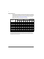
Chopper data table . . . . . . . . . . . . . . . . . . . . . . . . . . . . . . . . . . . . . . . . . . . . . . . . . . . . . . . 114
Resistor selection table . . . . . . . . . . . . . . . . . . . . . . . . . . . . . . . . . . . . . . . . . . . . . . . . . . . . 115
Resistor installation and wiring . . . . . . . . . . . . . . . . . . . . . . . . . . . . . . . . . . . . . . . . . . . . . . . . . . . 116
Contactor protection of drive . . . . . . . . . . . . . . . . . . . . . . . . . . . . . . . . . . . . . . . . . . . . . . . . 116
Braking circuit commissioning . . . . . . . . . . . . . . . . . . . . . . . . . . . . . . . . . . . . . . . . . . . . . . . . . . . . 116

Table of contents
14
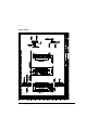
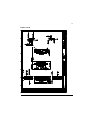
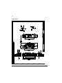
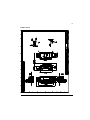
Dimension drawings
What this chapter contains . . . . . . . . . . . . . . . . . . . . . . . . . . . . . . . . . . . . . . . . . . . . . . . . . . . . . . .119
Frame size A . . . . . . . . . . . . . . . . . . . . . . . . . . . . . . . . . . . . . . . . . . . . . . . . . . . . . . . . . . . . . . . . .120
Frame size B . . . . . . . . . . . . . . . . . . . . . . . . . . . . . . . . . . . . . . . . . . . . . . . . . . . . . . . . . . . . . . . . .121
Frame size C . . . . . . . . . . . . . . . . . . . . . . . . . . . . . . . . . . . . . . . . . . . . . . . . . . . . . . . . . . . . . . . . .122
Frame size D . . . . . . . . . . . . . . . . . . . . . . . . . . . . . . . . . . . . . . . . . . . . . . . . . . . . . . . . . . . . . . . . .123
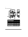
Mains chokes (type CHK-0x) . . . . . . . . . . . . . . . . . . . . . . . . . . . . . . . . . . . . . . . . . . . . . . . . . . . . .124
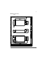
EMC filters (type JFI-x1) . . . . . . . . . . . . . . . . . . . . . . . . . . . . . . . . . . . . . . . . . . . . . . . . . . . . . . . . .125
JFI-A1 . . . . . . . . . . . . . . . . . . . . . . . . . . . . . . . . . . . . . . . . . . . . . . . . . . . . . . . . . . . . . . . . . .125
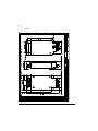
JFI-B1 . . . . . . . . . . . . . . . . . . . . . . . . . . . . . . . . . . . . . . . . . . . . . . . . . . . . . . . . . . . . . . . . . .126
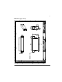
EMC filters (type JFI-0x) . . . . . . . . . . . . . . . . . . . . . . . . . . . . . . . . . . . . . . . . . . . . . . . . . . . . . . . . .127
Brake resistors (type JBR-xx) . . . . . . . . . . . . . . . . . . . . . . . . . . . . . . . . . . . . . . . . . . . . . . . . . . . . .129
Further information
Product and service inquiries . . . . . . . . . . . . . . . . . . . . . . . . . . . . . . . . . . . . . . . . . . . . . . . . . . . . .131
Product training . . . . . . . . . . . . . . . . . . . . . . . . . . . . . . . . . . . . . . . . . . . . . . . . . . . . . . . . . . . . . . .131
Providing feedback on ABB Drives manuals . . . . . . . . . . . . . . . . . . . . . . . . . . . . . . . . . . . . . . . . .131
Document library on the Internet . . . . . . . . . . . . . . . . . . . . . . . . . . . . . . . . . . . . . . . . . . . . . . . . . .131

Introduction to this manual
15
Introduction to this manual
What this chapter contains
This chapter describes the intended audience and contents of this manual. It
contains a flowchart of steps in checking the delivery, installing and commissioning
the drive. The flowchart refers to chapters/sections in this manual and other
manuals.
Compatibility
The manual is compatible with the ACS850-04 drive modules of frame sizes A to D.
Intended audience
This manual is intended for people who plan the installation, install, commission, use
and service the drive. Read the manual before working on the drive. The reader is
expected to know the fundamentals of electricity, wiring, electrical components and
electrical schematic symbols.
This manual is written for readers worldwide. Both SI and imperial units are shown
wherever appropriate.
Categorization according to the frame size
Some instructions, technical data and dimensional drawings which concern only
certain frame sizes are marked with the symbol of the frame size A, B, C or D. The
frame size is marked on the drive designation label. The frame size of each drive
type is also indicated in the rating tables in chapter Technical data.
Categorization according to the + code
The instructions, technical data and dimensional drawings which concern only
certain optional selections are marked with + codes, e.g. +L500. The options
included in the drive can be identified from the + codes visible on the type
designation label of the drive. The + code selections are listed in chapter Operation
principle and hardware description under Type designation key.
Contents
The chapters of this manual are briefly described below.
Safety instructions give safety instructions for the installation, commissioning,
operation and maintenance of the drive.
Introduction to this manual lists the steps in checking the delivery and installing and
commissioning the drive and refers to chapters/sections in this manual and other
manuals for particular tasks.

Introduction to this manual
16
Operation principle and hardware description describes the drive module.
Planning the cabinet assembly guides in planning the installation of the drive module
into a user-defined cabinet.
Mechanical installation instructs how to place and mount the drive.
Planning the electrical installation instructs on the motor and cable selection, the
protections and the cable routing.
Electrical installation instructs on how to wire the drive.
Installation checklist contains a list for checking the mechanical and electrical
installation of the drive.
Start-up refers to the start-up instructions of the drive.
Maintenance lists periodic maintenance actions along with work instructions.
Technical data contains the technical specifications of the drive, e.g. the ratings,
sizes and technical requirements and provisions for fulfilling the requirements for CE
and other markings.
Mains chokes details the optional mains chokes available for the drive.
EMC filters details the EMC filtering options available for the drive.
du/dt and common mode filtering lists the du/dt and common mode filtering options
available for the drive.
Resistor braking describes how to select, protect and wire brake resistors.
Dimension drawings contains the dimensional drawings of the drive and connected
equipment.

Introduction to this manual
17
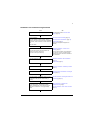
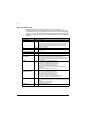
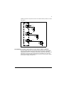
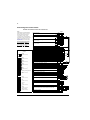
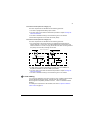
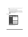
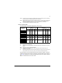
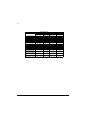
Installation and commissioning flowchart
Task See
Identify the frame size of your drive: A, B, C or D. Drive designation label or Technical data:
Ratings (page 83)
Plan the installation.
Check the ambient conditions, ratings, required
cooling air flow, input power connection, compatibility
of the motor, motor connection, and other technical
data.
Select the cables.
Planning the cabinet assembly (page 29)
Planning the electrical installation (page 43)
Technical data (page 83)
Option manual (if optional equipment is
included)
Unpack and check the units.
Check that all necessary optional modules and
equipment are present and correct.
Only intact units may be started up.
Mechanical installation: Contents of the
package (page 37)
If the converter has been non-operational for
more than one year, the converter DC link
capacitors need to be reformed. Ask ABB for
more information.
Check the installation site. Mechanical installation: Before installation
(page 39)
Technical data (page 83)
Install the drive in a cabinet. Mechanical installation: Installation procedure
(page 40)
Route the cables. Planning the electrical installation: Routing the
cables (page 50)
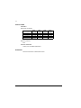
Check the insulation of the supply cable, the motor
and the motor cable, and the resistor cable (if
present).
Electrical installation: Checking the insulation of
the assembly (page 55)
If the drive is about to be connected to an IT
(ungrounded) system, disconnect the internal
varistors and EMC filters. Also note that using an
EMC filter is not allowed in an IT (ungrounded)
system.
Safety instructions: Installation and
maintenance work (page 6)
Electrical installation: Power cable connection
(page 56)

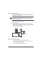
Introduction to this manual
18
Connect the power cables.
Connect the control and the auxiliary control cables.
Electrical installation: Power cable connection
(page 56) and Connecting the control cables
(page 66)
For optional equipment:
Mains chokes (page 101)
EMC filters (page 103)
Resistor braking (page 113)
Manuals for any optional equipment
Check the installation. Installation checklist (page 73)
Commission the drive. Start-up (page 75)
Appropriate firmware manual
Commission the brake chopper if required. Resistor braking (page 113)
Operating of the drive: start, stop, speed control etc. Appropriate firmware manual
Task See

Introduction to this manual
19
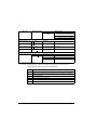
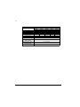
Terms and abbreviations
Term/Abbreviation Explanation
CHK-xx Series of optional mains chokes
EFB Embedded fieldbus
EMC Electromagnetic compatibility
FIO-01 Optional digital I/O extension module
FIO-11 Optional analog I/O extension module
FIO-21 Optional analog/digital I/O extension module
FEN-01 Optional TTL encoder interface module
FEN-11 Optional absolute encoder interface module
FEN-21 Optional resolver interface module
FEN-31 Optional HTL encoder interface module
FCAN-01 Optional CANopen adapter module
FDNA-01 Optional DeviceNet adapter module
FECA-01 Optional EtherCAT
®
adapter module
FENA-11 Optional Ethernet adapter module. Supports the Ethernet/IP, Modbus/TCP
and PROFINET IO protocols
FLON-01 Optional L
ONWORKS
®
adapter module
FPBA-01 Optional PROFIBUS DP adapter module
Frame (size) Size of the drive module. This manual deals with frames A, B, C and D. To
determine the frame size of a drive module, refer to the drive designation
label attached to the drive, or the rating tables in chapter Technical data.
FSCA-0x Optional Modbus/RTU adapter module
IGBT Insulated Gate Bipolar Transistor; a voltage-controlled semiconductor type
widely used in inverters due to their easy controllability and high switching
frequency.
I/O Input/Output
JBR-xx Series of optional brake resistors
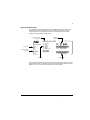
JCU The control unit of the drive module. The JCU is installed on top of the
power unit. The external I/O control signals are connected to the JCU, or
optional I/O extensions mounted on it.
JFI-xx Series of optional EMC filters
JMU The memory unit attached to the control unit of the drive.
JPU Power unit; see the definition below.
Power unit Contains the power electronics and connections of the drive module. The
JCU is connected to the power unit.
RFI Radio-frequency interference

Introduction to this manual
20
Page is loading ...
Page is loading ...
Page is loading ...
Page is loading ...
Page is loading ...
Page is loading ...
Page is loading ...
Page is loading ...
Page is loading ...
Page is loading ...
Page is loading ...
Page is loading ...
Page is loading ...
Page is loading ...
Page is loading ...
Page is loading ...
Page is loading ...
Page is loading ...
Page is loading ...
Page is loading ...
Page is loading ...
Page is loading ...
Page is loading ...
Page is loading ...
Page is loading ...
Page is loading ...
Page is loading ...
Page is loading ...
Page is loading ...
Page is loading ...
Page is loading ...
Page is loading ...
Page is loading ...
Page is loading ...
Page is loading ...
Page is loading ...
Page is loading ...
Page is loading ...
Page is loading ...
Page is loading ...
Page is loading ...
Page is loading ...
Page is loading ...
Page is loading ...
Page is loading ...
Page is loading ...
Page is loading ...
Page is loading ...
Page is loading ...
Page is loading ...
Page is loading ...
Page is loading ...
Page is loading ...
Page is loading ...
Page is loading ...
Page is loading ...
Page is loading ...
Page is loading ...
Page is loading ...
Page is loading ...
Page is loading ...
Page is loading ...
Page is loading ...
Page is loading ...
Page is loading ...
Page is loading ...
Page is loading ...
Page is loading ...
Page is loading ...
Page is loading ...
Page is loading ...
Page is loading ...
Page is loading ...
Page is loading ...
Page is loading ...
Page is loading ...
Page is loading ...
Page is loading ...
Page is loading ...
Page is loading ...
Page is loading ...
Page is loading ...
Page is loading ...
Page is loading ...
Page is loading ...
Page is loading ...
Page is loading ...
Page is loading ...
Page is loading ...
Page is loading ...
Page is loading ...
Page is loading ...
Page is loading ...
Page is loading ...
Page is loading ...
Page is loading ...
Page is loading ...
Page is loading ...
Page is loading ...
Page is loading ...
Page is loading ...
Page is loading ...
Page is loading ...
Page is loading ...
Page is loading ...
Page is loading ...
Page is loading ...
Page is loading ...
Page is loading ...
Page is loading ...
Page is loading ...
Page is loading ...
-
 1
1
-
 2
2
-
 3
3
-
 4
4
-
 5
5
-
 6
6
-
 7
7
-
 8
8
-
 9
9
-
 10
10
-
 11
11
-
 12
12
-
 13
13
-
 14
14
-
 15
15
-
 16
16
-
 17
17
-
 18
18
-
 19
19
-
 20
20
-
 21
21
-
 22
22
-
 23
23
-
 24
24
-
 25
25
-
 26
26
-
 27
27
-
 28
28
-
 29
29
-
 30
30
-
 31
31
-
 32
32
-
 33
33
-
 34
34
-
 35
35
-
 36
36
-
 37
37
-
 38
38
-
 39
39
-
 40
40
-
 41
41
-
 42
42
-
 43
43
-
 44
44
-
 45
45
-
 46
46
-
 47
47
-
 48
48
-
 49
49
-
 50
50
-
 51
51
-
 52
52
-
 53
53
-
 54
54
-
 55
55
-
 56
56
-
 57
57
-
 58
58
-
 59
59
-
 60
60
-
 61
61
-
 62
62
-
 63
63
-
 64
64
-
 65
65
-
 66
66
-
 67
67
-
 68
68
-
 69
69
-
 70
70
-
 71
71
-
 72
72
-
 73
73
-
 74
74
-
 75
75
-
 76
76
-
 77
77
-
 78
78
-
 79
79
-
 80
80
-
 81
81
-
 82
82
-
 83
83
-
 84
84
-
 85
85
-
 86
86
-
 87
87
-
 88
88
-
 89
89
-
 90
90
-
 91
91
-
 92
92
-
 93
93
-
 94
94
-
 95
95
-
 96
96
-
 97
97
-
 98
98
-
 99
99
-
 100
100
-
 101
101
-
 102
102
-
 103
103
-
 104
104
-
 105
105
-
 106
106
-
 107
107
-
 108
108
-
 109
109
-
 110
110
-
 111
111
-
 112
112
-
 113
113
-
 114
114
-
 115
115
-
 116
116
-
 117
117
-
 118
118
-
 119
119
-
 120
120
-
 121
121
-
 122
122
-
 123
123
-
 124
124
-
 125
125
-
 126
126
-
 127
127
-
 128
128
-
 129
129
-
 130
130
-
 131
131
-
 132
132


Ask a question and I''ll find the answer in the document
Finding information in a document is now easier with AI
Related papers
-
ABB ACS850 series User manual
-
-
ABB ACS850-04 series Quick Installation Manual
-
-
-
-
-
-
-
Other documents
-
 Zambelis LIGHTS 180031-D Installation guide
-
Duracell 675 User manual
-
Igloo In-Home Display User manual
-
Aztech In-Home Display (IHD) Installation guide
-
Lenze m550-H Mounting Instruction
-
FLIR M-Series Installation guide
-
Oriental motor MBS12-EC Operating instructions
-
LG HOME8SAC Installation guide
-
 MFJ 701 User manual
-

