Page is loading ...

P/N 466-5418 • REV A • 7MAR18 © 2018 United Technologies Corporation. All rights reserved
TX-E121 Command Button – Installation Instructions
PLEASE SEE REVERSE SIDE FOR IMPORTANT PRODUCT WARNINGS
AND DISCLAIMER INFORMATION.
Description (See reverse side for product warnings and disclaimers)
The TX-E121 Command Button allows for up to 3 different commands, scenes, and/or automations to be
triggered through three different button pressing sequences. To the security panel, the button appears as
3 door/window sensor zones, each with their own unique TX-ID (located on the printed card included in
the box). Depending on the security panel’s capability and/or the capability of the interactive services
utilized with the panel, triggering any of the Command Button’s 3 zones can be set up as the initiating
action to then trigger a pre-configured automation or rule.
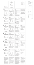
Figure 1: TX-E121 Command Button
Enrolling
Keep in mind that to the panel, each command appears as a door/window sensor open, followed by an
automatic restoral. When enrolling the device, it is recommended to name each zone accordingly so they
can easily be assigned to the scene of your choice. For instance, zone #1 = “CB1 ST” (command button
single tap), zone #2 = “CB1 DT” (for double tap), and zone #3 = “CB1 PH” (for press and hold).
To enroll the command-button into the panel utilizing the panel’s “Learn Mode” procedure, the sensor
needs to be placed into enrollment mode. To enter enrollment mode on the button, follow these steps:
1) Press and hold the button for approximately 10 seconds. During this 10 second time frame, the
LED will blink three times, then remain on for 3 more seconds. Continue holding down the button and after
a total of approximately 10 seconds, the LED will quickly flash 5 times indicating that enrollment mode has
been enabled.
2) With the panel in learn mode, briefly tap the button once to trigger a tamper transmission for zone
#1. This should successfully learn it into the panel. If the panel does not respond, wait for the LED to shut
off and try pressing the button again, until successful enrollment occurs.
3) After the panel has recognized the first zone, be sure to assign it to a zone type that is “chime
only”. Because each zone transmits as a door/window sensor, a chime-only zone type is necessary to
ensure that the panel does not go into alarm if the system is armed and the end user wishes to activate a
particular scene or automation.
For Simon, Concord, and NetworX control panels, zone type 25 is recommended.
For Ultrasync control panels, set the sensor type to “Event Only”
4) Take note that the command button automatically ends the enrollment mode after 15 seconds of
not sending any commands (i.e. after pressing and holding for 10 seconds and verifying enrollment is
enabled with the 5 LED flashes, if the button isn’t pressed for 15 seconds immediately after the enrollment
mode activation, it will revert back to its normal operation of sending open + automatic restorals on button
presses vs sending tampers). Depending on how long it takes to set up each zone on the panel after a
zone is learned in, you may need to re-enter enrollment mode again (holding down for 10 seconds) when
ready to enroll zones 2 and 3.
Operating Instructions
Each of the Command Button’s three different command configurations (Single tap, double tap, & press
and hold) can be used as the initiating action to trigger a pre-configured scene, automation, or other smart
device(s). To learn how to set up scenes/automations, refer to the instructions provided by the panel’s
interactive services provider.
Briefly tap the button once to trigger an “OPEN” transmission for zone #1. The red LED will flash
once, and then re-illuminate, staying illuminated for approximately 3 seconds. During this continual
illumination period, the sensor is sending an automatic restoral transmission. Wait until the LED light is no
longer illuminated to send another command.
Double tapping the button will trigger an “OPEN” transmission for zone #2. The red LED will flash
twice, and then re--illuminate, staying illuminated for approximately 3 seconds. During this continual
illumination period, the sensor is sending an automatic restoral transmission. Wait until the LED light is no
longer illuminated to send another command.
Press and hold the button for approximately 3 seconds to trigger an “OPEN” transmission for
zone #3. The red LED will flash three times, and then re-illuminate, staying illuminated for approximately 3
seconds. During this continual illumination period, the sensor is sending an automatic restoral
transmission. Wait until the LED light is no longer illuminated to send another command.
Mounting
Included with this device is one piece of double sided tape for permanently securing the Command Button
in a desired location. Choose a suitable location for the sensor by following the procedure in section
“Testing the Sensor” ensuring desired signal strength is achieved.
Where possible, install sensors within 100 ft. (30 m) of the panel. While a transmitter may have an open-
air range of 500 ft. (150 m) or more, the environment at the installation site may have a significant effect
on operational range. Changing a sensor location may improve wireless communication.
For reliable bonding, ensure the surface is clean and dry. Apply the tape to the backside of the sensor,
and then to the desired location. Apply firm pressure for several seconds. When mounting with double
sided tape, ensure temperatures are above 50°F and will remain above 50°F for at least 24 hours to
ensure proper bond. After 24 hours, the bond will hold at lower temperatures.
Sensor Testing (Test before permanently mounting, as well as weekly)
The sensor test verifies proper communication between the sensor and the panel/receiver. To test the
sensor, refer to the specific panel/receiver documentation and do the following:
1) Put the panel/receiver into sensor test mode
2) Press the Command Button once – the sensor will then transmit a signal
3) Listen for the siren beeps to determine the number of packets received (Each beep indicates
one packet received, out of 8 total). It is recommended that the panel receives at least 5 out
of 8 packets from the desired sensor location. If the panel is consistently receiving less than
5 out of 8 packets from a certain location, try rotating the sensor and/or relocating the sensor
to an area where it can achieve better communication.
4) Exit sensor test mode when proper communication between the sensor and panel/receiver
has been verified.
Replacing the Battery
The Command Button comes pre-installed with a single Panasonic CR2032 Lithium coin-cell battery that
provides 5 years of battery life under normal usage conditions. When the battery is low, a signal will be
sent to the control panel. To replace the battery, do the following:
1) Insert a small coin (such as a dime) into one of the corner notches of the Command Button
and twist to release the top cover from the bottom cover.
2) Set the top cover aside, and gently remove the circuit board from the bottom case
3) Flip the circuit board over, revealing the Panasonic CR2032 coin cell battery. Remove the
battery and insert a new Panasonic CR2032 battery, ensuring that the positive side (+) of
the battery is facing towards the (+) sign indicated on the battery holder
4) Place the circuit board back into the bottom case with the battery side facing down. Take
note that the board will only fit properly into the bottom case in one direction. On one side of
the middle of the circuit board is a small notch. This notch should align with a small piece of
plastic extending out from the inside edge of the circuit board. When properly inserted, the
circuit board will fit snugly and securely inside the bottom case.
5) Replace the front cover back onto the bottom case.

P/N 466-5418 • REV A • 7MAR18 © 2018 United Technologies Corporation. All rights reserved
Specifications
TX-E121
RF Frequency
319.5 MHz – (Crystal Based)
Compatibility
Interlogix 319.5 MHz control panels/receivers
Battery Type
CR2032 (Panasonic)
Typical Battery Life
Up to 5 years at 68° F (20° C)
Operating Temperature
Range
32° to 110°F (0° to 43°C)
Supervisory Interval
64 Minutes
Storage Temperature Range
-30 to 140°F (-34 to 60°C)
Dimensions
(L x W x H)
1.2 in x 1.2 in x 0.4 in
FCC Compliance Statement
This equipment has been tested and found to comply with the limits for a Class B digital device, pursuant to Part 15 of the FCC
Rules. These limits are designed to provide reasonable protection against harmful interference in a residential installation.
This equipment generates, uses, and can radiate radio frequency energy and, if not installed and used in accordance with the
instructions, may cause harmful interference to radio communications. However, there is no guarantee that interference will not
occur in a particular installation.
If this equipment does cause harmful interference to radio or television reception, which can be determined by turning the
equipment off and on, the user is encouraged to try to correct the interference by one or more of the following measures:
• Reorient or relocate the receiving antenna.
• Increase the separation between the equipment and receiver.
• Connect the equipment into an outlet on a circuit different from that to which the receiver is connected.
• Consult the dealer or an experienced radio/TV technician for help.
Changes or modifications not expressly approved by UTC Fire and Security could void the user’s authority to operate the
equipment.
This device complies with Industry Canada license-exempt RSS standard(s). Operation is subject to the following two
conditions: (1) this device may not cause interference, and (2) this device must accept any interference, including
interference that may cause undesired operation of the device.
Cet appareil est conforme avec Industrie Canada exempts de licence standard RSS (s). Son fonctionnement est soumis aux
deux conditions suivantes: (1) cet appareil ne doit pas provoquer d'interférences et (2) cet appareil doit accepter toute
interférence, y compris celles pouvant causer un mauvais fonctionnement de l'appareil.
In accordance with FCC requirements of human exposure to radiofrequency fields, the radiating element shall be installed
such that a minimum separation distance of 20 cm is maintained from the general population.
Conformément aux exigences d'Industrie Canada en matière d'exposition humaine aux champs de radiofréquences,
l'élément rayonnant doit être installé de telle sorte qu'une distance minimale de 20 cm soit maintenue par rapport à la
population générale.
FCC: XQC-TXE121
IC: 9863B-TXE121
This Class B digital apparatus complies with Canadian ICES-3B.
Cet appareil numérique de la classe B est conforme à la norme NMB-003 du Canada.
Contact information
For contact information, visit us online at www.interlogix.com.
For technical support, see www.interlogix.com/support
Copyright
Copyright © 2018 United Technologies Corporation. All rights reserved.
Trademarks
Interlogix is a registered trademark of United Technologies Corporation. Interlogix is part of UTC Climate, Controls & Security, a
unit of United Technologies Corporation.
Product Warnings and Disclaimers
WARNING: CHOKING HAZARD - Small parts. Keep away from children.
THESE PRODUCTS ARE INTENDED FOR SALE TO, AND INSTALLATION BY, AN EXPERIENCED SECURITY
PROFESSIONAL. UTC FIRE & SECURITY CANNOT PROVIDE ANY ASSURANCE THAT ANY PERSON OR ENTITY
BUYING ITS PRODUCTS, INCLUDING ANY “AUTHORIZED DEALER”, IS PROPERLY TRAINED OR EXPERIENCED TO
CORRECTLY INSTALL SECURITY RELATED PRODUCTS.
For more information on warranty disclaimers and product safety information, please check
https://firesecurityproducts.com/policy/product-warning or scan the following code:
/