Miller KH387456, your new air plasma cutting system, is a high-performance tool designed to deliver precise and efficient cutting results. With a rated output of 26 amps at 115 volts and 3.1 kVA input power, it offers ample power for various cutting applications. The system utilizes air or nitrogen as the plasma gas, ensuring a clean and precise cut. The cutting capacity extends up to 1/4 inch (6 mm) at 60 PSI (414 kPa), making it suitable for a range of materials.
May
1997
Form:
OM-181
460B
Effective
With
Serial
No.
KH387456
OWNERS
MANUAL
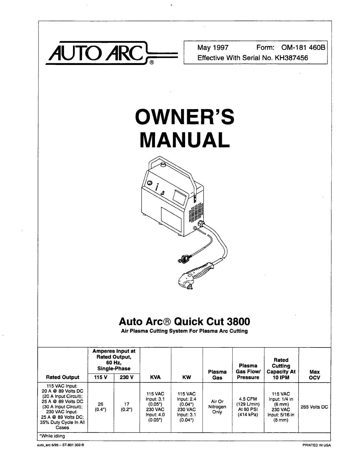
Auto
Arcfi
Quick
Cut
3800
Air
Plasma
Cutting
System
For
Plasma
Arc
Cutting
Rated
Output
Amperes
Input
at
Rated
Output,
60
Hz,
Single-Phase
KVA
KW
Plasma
Gas
Plasma
Gas
Flow/
Pressure
Rated
Cutting
Capacity
At
10
1PM
Max
OCV
115
V
230
V
115
VAC
Input:
20
A
'
89
Volts
DC
(20
A
Input
Circuit);
25
A
'
89
Volts
DC
(30
A
Input
Circuit);
230
VAC
Input:
25
A
'
89
Volts
DC;
35%
Duty
Cycle
In
All
Cases
26
(0.4*)
17
(0.2*)
115
VAC
Input:
3.1
(0.05*)
230
VAC
Input.
4.0
(0.05*)
115
VAC
Input:
2.4
(O.04~)
230
VAC
Input:
3.1
(0.04*)
Air
Or
Nitrogen
Only
4.5
CFM
(129
Umin)
At
60
PSI
(414
kPa)
115
VAC
Input:
1/4
in
(6
mm)
230
VAC
Input:
5/16
in
(8
mm)
265
Volts
DC
While
idling
auto_arc
6/95
ST-801
302-B
PRINTED
IN
USA
ax
N~t
LIMITED
WARRANTY
Effective
January
1,
1997
(Equipment
with
a
serial
number
preface
of
KU
or
newer)
This
limited
werrenty
supersedes
all
previous
msnufscturers
wsrrenties
snd
is
exclusive
with
no
other
gusrentses
or
wsrrsnties
expressed
or
implied.
LIMITED
WARRANTY
Subject
to
the
terms
snd
conditions
below,
wsrrsnts
to
its
originsl
retell
purcheserthet
new
equipment
sold
efter
the
effective
dste
of
this
lim
ited
werrerrty
is
free
of
defects
in
msterlsl
end
worirmenship
et
the
time
it
is
shipped
from
fectory.
THIS
WARRANTY
IS
EXPRESSLY
IN
LIEU
OF
ALL
OThER
WAR
RANTIES,
EXPRESS
OR
IMPLIED,
INCLUDING
THE
WARRANTiES
OF
MER
CHANTABILITY
AND
FITNESS.
Within
the
warrentyperiods
listed
below,
manufecturerwilt
repeiror
replece
snywer
rented
pelts
or
components
that
fell
due
to
such
defects
in
meterial
orworkmanehip.
Menufecturer
must
be
notified
in
writing
within
thirty
(30)
days
of
such
defect
or
fell
ure,
et
which
time
menufecturer
will
provide
instructions
on
the
werrenty
cleim
pro
cedures
to
be
followed.
Menufecturer
shell
honor
warrenfy
claims.
on
werrented
equipment
listed
below
in
the
event
of
such
e
feilure
within
the
warrenty
time
periods.
All
werrenty
time
periods
etsi
on
the
dete
thst
the
equipment
wex
delivered
to
the
originel
rebel
purcheser,
or
one
yeer
eher
the
equipment
is
sent
to
e
North
Americen
distributor
or
eighteen
months
efter
the
equipment
is
sent
to
en
Intemetionel
distributor.
1.
5YeamPerts3YeersLebor
Originel
msin
power
rectifiers
*
Invertem
(input
end
output
rectifiers
onily)
2.
3
Yeera
Pens
and
Lsbor
Trensformer/Rectifier
Power
Sources
Pleems
Arc
Cutting
Power
Sources
Semi-Automatic
end
Autometrc
Wire
Feeders
*
Inverter
Power
Supplies
Inteltitig
Robots
Engine
Driven
Welding
Generetom
(NOTE:
Engines
ere
werrented
eeperetely
by
the
engine
menufecturer.)
3.
1
Yeer
Pens
end
Lsbor
Motor
Driven
Gune
(w/exception
of
Spoolmete
185)
Process
Controllers
*
Poeitioners
end
Controllers
*
Autometic Motion
Devices
Orbitsl
Weld
Heede
IHPS
Power
Sources
*
Weter
Coolent
Systems
*
HFUnits
Grids
*
Spot
Welders
Loed
Benks
SoXTrensformere
Running
Geer/Treilers
Pleeme
Cuthng
Torches
(except
APT,
ZIPCUT
&
PLAZCUT
Models)
Deutz
Engines
(outside
North
Americe)
Field
Options
(NOTE:
Field
options
ere
covered
under
the
limited
werrenty
for
the
re
meining
werrenty
period
of
the
product
they
ere
inetelled
in,
or
fore
mini
mum
of
one
yeer
whichever
is
greeter.)
4.
6
Months
Bettenee
5.
gO
Deye
Pens
end
Labor
I
*
MIG
Guns/hG
Torches
APT,
ZIPCUT
&
PLAZCUT
Model
Plesme
Cutting
Torches
*
Remote
Controls
Accessory
lOts
Replacement
Pens
(No
lebor)
*
Spoolmete
185
Limited
Werrenty
ehsll
not
epply
to:
1.
Items
fumished
bymenufecturer,
but
msnufsctured
by
others,
such
es
engines
ortrsde
accessonee.
These
items
ere
covered
bythe
menufecturerewerrenty,
if
any.
2.
Consumeble
components;
such
as
contect
tips,
cutting
nozzles,
contectors,
reteye,
brushes,
slip
rings,
or
pens
thet
fell
due
to
normel
weer.
3.
Equipment
thet
hes
been
modified
by
eny
party
other
then
menufecturer,
or
equipment
thet
hex
been
improperiy
inetelled,
improperfy
opersted
or
misused
bsssd
upon
industry
atenderds,
or
equipment
which
has
not
hed
reexoneble
end
necexeery
meintenence,
or
equipment
which
hex
been
used
for
operstion
outside
of
the
specificetions
for
the
equipment.
MANUFACTURERS
PRODUCTS
ARE
INTENDED
FOR
PURCHASE
AND
USE
BY
COMMERCIALI1NDUSTRIAL
USERS
AND
PERSONS
TRAINED
AND
EXPE
RIENCED
IN
ThE
USE
AND
MAINTENANCE
OF
WELDING
EOUIPMENT
In
the
event
of
5
werrenty
claim
covered
by
this
werrenry,
the
exclusive
remedies
shell
be,
xl
menufecturers
option:
(1)
repeir
or(2(
replacement;
or,
where
authorized
in
writing
by
manufacturer
in
eppropriete
cexex,
(3)
the
reeeoneble
cost
of
repeir
or
reptecement
et
en
euthorized
service
ststion;
or
(4)
payment
of
orcredit
for
the
pur
chese
price
(less
reesoneble
deprecietion
bxsed
upon
ectuel
use)
upon
retum
of
the
goods
et
customers
risk
end
expense.
Mxnufecturere
option
of
repeir
or
replece
ment
wilt
be
FOB.,
Fectory
at
Appleton,
Wisconsin,
or
FOB.
et
en
euthorized
ser
vice
facility
as
determined
by
menufecturer.
Therefore
no
compensation
or
reim
bursement
for
trensportation
costs
of
eny
kind
will
be
allowed,
TO
THE
EXTENT
PERMITTED
BY
LAW,
THE
REMEDIES
PROVIDED
HEREIN
ARE
THE
SOLE
AND
EXCLUSIVE
REMEDIES.
IN
NO
EVENTSHALL
MANUFAC
TURER
BE
UABLE
FOR
DIRECT,
INDIRECT,
SPECIAL,
INCIDENTAL
OR
CON
SEQUENT1AL
DAMAGES
(INCLUDING
LOSS
OF
PROFIT),
WHETHER
BASED
ON
CONTRACT,
TORT
OR
ANY
OTHER
LEGAL
THEORY.
ANY
EXPRESS
WARRANTY
NOT
PROVIDED
HEREIN
AND
ANY
IMPLIED
WAR
RANTY,
GUARANTY
OR
REPRESENTA11ON
ASTO
PERFORMANCE,
AND
ANY
REMEDY
FOR
BREACH
OF
CONTRACT
TORT
OR
ANY
OTHER
LEGAL
THEORY
WHICH,
BUT
FOR
THIS
PROVISION,
MIGHTARISE
BY
IMPLICATiON,
OPERA11ON
OF
LAW,
CUSTOM
OF
TRADE
OR
COURSE
OF
DEALING,
IN
CLUDING
ANY
IMPLIED
WARRANTY
OF
MERCHANTABILITY
OR
FITNESS
FOR
PARTICULAR
PURPOSE,
WiTH
RESPECT
TO
ANY
AND
ALL
EOUIPMENT
FURNISHED
BY
MANUFACTURER
IS
EXCLUDED
AND
DISCLAIMED
BY
MAN
UFACTURER.
Some
etetes
in
the
U.S.A.
do
not
ellow
limitations
of
how
long
en
implied
werrerrty
lasts,
or
the
exclusion
of
incidental,
indirect,
special
or
consequentiel
dameges,
so
the
above
limitetlon
or
exclusion
mey
not
epply
to
you.
This
warrenty
provides
spe
cific
legal
rights,
end
other
rights
may
be
eveileble,
but
mey
vary
from
state
to
stete.
In
Ceneda,
legislation
in
some
provinces
provides
for
certein
additionel
warranties
or
remedies
other
then
as
stated
herein,
end
to
the
exrent
that
they
mey
not
be
weived,
the
limitations
end
exclusions
set
out
above
mey
not
epply.
This
Limited
Werranty
provides
specific
legsl
rights,
end
other
rights
mey
be
evaileble,
but
mey
very
from
province
to
province.
:i~U
J
L
If
__~1
RECEIVING-HANDLING
Before
Unpacking
eqUjpment,
check
carton
for
any
damage
that
may
have
occurred
during
shipment,
File
any
claims
for
(oss
or
damaga
with
the
delivering
carrier.
AssiStance
for
filing
or
sett(ing
claims
may
be
obtained
from
distributor
and/or
eqUjpment
manufacturers
Transportation
Department.
When
requesting
information
about
thjs
equipment,
always
provide
Model
Designation
and
Serial
or
Style
Number,
Use
the
following
spaces
to
record
Model
Designation
and
Serial
or
Style
Number
of
your
unit.
The
information
is
loca(ed
on
the
rating
label
or
nameplate.
Model
_________
Serial
or
Style
No.
Date
of
Purchase
brand_wer
~
SECTION
1
-
SAFETY
FOR
PLASMA
ARC
CUTTING
OM-181
460B
5/9~
8afety._poml
4195
1-1.
Symbol
Usage
4A
Means
Warning!
Watch
Out!
There
are
possible
hazards
with
this
A
Marks
a
special
safety
message.
procedure!
The
possible
hazards
are
shown
in
the
adjoining
symbols.
~
Means
NOTE;
not
safety
related.
I
~
This
group
of
symbols
means
Warning!
Watch
Out!
possible
ELECTRIC
SHOCK,
MOVING
PARTS,
and
HOT
PARTS
hazards.
Consult
symbols
and
re!ated
instructions
be!ow
for
necessary
I
________________________________
actions
to
avoid
the
hazards.
1-2.
Plasma
Arc
Cutting
Hazards
CUTTING
can
cause
fire
or
explosion.
Hot
metal
and
sparks
blow
out
from
the
cuthng
arc.
The
flying
sparks
and
hot
metal,
hot
workpiece,
and
hot
equipment
can
cause
fires
and
bums.
Check
and
be
sure
the
area
is
safe
before
doing
any
cutting.
1.
Protect
yourself
and
others
from
flying
sparks
and
hot
metal.
2.
Do
not
cut
where
flying
sparks
can
strike
flammable
matenal.
3.
Remove
all
flammables
within
35
ft
(10.7
m)
of
the
cutting
arc.
If
this
is
not
possible,
tightly
cover
them
with
approved
covers.
4.
Be
alert
that
sparks
and
hot
materials
from
cutting
can
easily
go
through
small
cracks
and
openings
to
adjacent
areas.
5.
Watch
for
fire,
and
keep
a
fire
extinguisher
nearby.
6.
Be
aware
that
cutting
on a
ceiling,
floor,
bulkhead,
or
partition
can
cause
fire
on
the
hidden
side.
7.
Do
not
cut
on
closed
containers
such
as
tanks
or
drums.
8.
Connect
work
cable
to
the
work
as
close
to
the
cutting
area
as
practical
to
prevent
cutting
current
from
traveling
long,
possibly
unknown
paths
and
causing
electric
shock
and
fire
hazards.
9.
Never
cut
containers
with
potentially
flammable
materials
inside
they
must
be
emptied
and
properly
cleaned
first.
10.
Do
not
cut
in
atmospheres
containing
explosive
dust
or
vapors.
11.
Do
not
cut
pressurized
cylinders,
pipes,
or
vessels.
12.
Do
not
cut
containers
that
have
held
combustibles.
13.
Wear
oil-free
protective
garments
such
as
leather
gloves,
heavy
shirt,
cuff
less
trousers,
high
shoes,
and
a
cap.
14.
Do
not
locate
unit
on
or
over
combustible
surfaces.
15.
Remove
any
combustibles,
such
as
a
butane
lighteror
matches,
from
your
person
before
doing
any
cutting.
8.
Check
and
be
sure
that
input
power
cord
ground
wire
is
properly
connected
to
ground
terminal
in
disconnect
box
orthat
cord
plug
is
connected
to
a
properly
grounded
receptacle
outlet
always
verify
the
supply
ground.
9.
When
making
input
connections,
attach
proper
grounding
conductor
first.
10.
Frequently
inspect
input
power
cord
for
damage
or
bare
wiring
replace
cord
immediately
if
damaged
bare
wiring
can
kill.
11.
Turn
offal!
equipment
when
not
in
use.
12.
Inspect
and
replace
any
worn
or
damaged
torch
cable
leads.
13.
Do
not
wrap
torch
cable
around
your
body.
14.
Ground
the
workpiece
to
a
good
electrical
(earth)
ground
if
required
by
codes.
15.
Use
only
well-maintained
equipment.
Repair
or
replace
damaged
parts
at
once.
16.
Wear
a
safety
harness
if
working
above
floor
level.
17.
Keep
all
panels
and
covers
securely
in
place.
18.
Do
not
bypass
or
try
to
defeat
the
safety
interlock
systems.
19.
Use
only
torch(es)
specified
in
Owners
Manual.
20.
Keep
away
from
torch
tip
and
pilot
arc
when
trigger
is
pressed.
21.
Clamp
work
cable
with
good
metal-to-metal
contact
to
workpiece
(not
piece
that
will
fall
away)
or
worktable
as
near
the
cut
as
practical.
1.
Wear
approved
face
shield
or
safety
goggles
with
side
shields.
2.
Wear
proper
body
protection
to
protect
skin.
3.
Wear
flame-resistant
ear
plugs
or
ear
muffs
to
prevent
sparks
from
entering
ears.
a
WARNING
The
symbols
shown
below
are
used
throughout
this
manual
to
call
attention
to
and
identify
possible
hazards.
When
you
see
the
symbol,
watch
out,
and
follow
the
related
instructions
to
avoid
the
hazard.
The
safety
information
given
below
is
only
a
summary
of
the
more
complete
safety
information
found
in
the
Safety
Standards
listed
in
Section
1-4.
Read
and
follow
all
Safety
Standards.
Only
qualified
persons
should
install,
operate,
maintain,
and
repair
this
unit.
During
operation,
keep
everybody,
especially
children,
away.
ELECTRIC
SHOCK
can
kill.
Touching
live
electrical
parts
can
cause
fatal
shocks
or
severe
bums.
The
torch
and
work
circuit
is
electrically
live
whenever
the
output
is
on.
The
input
power
circuit
and
machine
internal
circuits
are
also
live
when
power
is
on.
Plasma
arc
cutting
requires
higher
voltages
than
welding
to
start
and
maintain
the
arc
(200
to
400
volts
dc
are
common),
but
also
uses
torches
designed
with
safety
interlock
systems
which
turn
off
the
machine
when
the
shield
cup
is
loosened
or
if
tip
touches
electrode
inside
the
nozzle.
Incorrectly
installed
or
improperly
grounded
equipment
is
a
hazard.
1.
Do
not
touch
live
electrical
parts.
2.
Wear
dry,
hole-free
insulating
gloves
and
body
protection.
3.
Insulate
yourself
from
work
and
ground
using
dry
insulating
mats
or
covers
big
enough
to
prevent
any
physical
contact
with
the
work
or
ground.
4.
Do
not
touch
torch
parts
if
in
contact
with
the
work
or
ground.
5.
Turn
off
power
before
checking,
cleaning,
or
changing
torch
parts.
6.
Disconnect
input
power
before
installing
or
servicing
this
equipment.
Lockout/tagout
input
power
according
to
OSHA
CFR
191
0.147
(see
Safety
Standards).
7.
Properly
install
and
ground
this
equipment
according
to
its
Owners
Manual
and
national,
state,
and
local
codes.
FLYING
SPARKS
AND
HOT
METAL
can
cause
injury.
Sparks
and
hot
metal
blow
out
from
the
cutting
arc.
Chipping
and
grinding
cause
flying
metal.
OM-181
460
Page
1
ARC
RAYS
can
burn
eyes
and
skin.
,~
Arc
rays
from
the
cutting
process
produce
intense
visible
and
invisible
(ultraviolet
and
infrared)
rays
-
that
can
bum
eyes
and
skin.
1.
Wear
face
protection
(helmet
or
shield)
with
correct
shade
of
filter
to
protect
your
face
and
eyes
when
cutting
or
watching.
ANSI
Z49.i
(see
Safety
Standards)
suggests
a
No.
9
shade
(with
No.
8
as
minimum)
for
all
cutting
currents
less
than
300
amperes.
Z49.i
adds
that
lighter
filter
shades
may
be
used
when
the
arc
is
hidden
by
the
workpiece.
As
this
is
normally
the
case
with
low
current
cutting,
the
shades
suggested
in
Table
1
are
provided
for
the
operators
convenience.
2.
Wear
approved
safety
glasses
with
side
shields.
3.
Use
protective
screens
or
barriers
to
protect
others
from
flash
and
glare;
warn
others
not
to
watch
the
arc.
4.
Wear
protective
clothing
made
from
durable,
flame-resistant
material
(wool
and
leather)
and
foot
protection.
NOISE
can
damage
hearing.
Prolonged
noise
from
some
cutting
applications
can
damage
hearing
if
levels
exceed
limits
specified
by
OSHA
(see
Safety
Standards).
5.
Use
approved
ear
plugs
or
ear
muffs
if
noise
level
is
high.
6.
Wam
others
nearby
about
noise
hazard.
FUMES
AND
GASES
can
hazardous
to
your
health.
be
Cutting
produces
fumes
and
gases.
Breathing
these
fumes
and
gases
can
be
hazardous
to
your
health.
Keep
your
head
out
of
the
fumes.
Do
not
breathe
the
fumes.
If
inside,
ventilate
the
area
and/or
use
exhaust
at
the
arc
to
remove
cutting
fumes
and
gases.
3.
If
ventilation
is
poor,
use
an
approved
air-supplied
respirator.
4.
Read
the
Material
Safety
Data
Sheets
(MSDSs)
and
the
manufacturers
instruction
for
metals
to
be
cut,
coatings,
and
cleaners.
5.
Work
in
a
confined
space
only
if
it
is
well
ventilated,
or
while
wearing
an
air-supplied
respirator.
Fumes
from
cutting~
and
oxygen
depletion
can
alter
air
quality
causing
injury
or
death.
Be
sure
the
breathing
air
is
safe.
6.
Do
not
cut
in
locations
near
degreasing,
cleaning,
or
spraying
operations.
The
heat
and
rays
of
the
arc
can
react
with
vapors
to
form
highly
toxic
and
irritating
gases.
7.
Do
not
cut
on
coated
metals,
such
as
galvanized,
lead,
or
cadmium
plated
steel,
unless
the
coating
is
removed
from
the
cutting
area,
the
area
is
well
ventilated,
and
if
necessary,
while
wearing
an
air-supplied
respirator.
The
coatings
and
any
metals
containing
these
elements
can
give
off
toxic
fumes
when
cut.
8.
Do
not
cut
containers
with
toxic
or
reactive
materials
inside
or
containers
that
have
held
toxic
or
reactive
materials
they
must
be
emptied
and
properly
cleaned
first.
CYLINDERS
can
explode
if
damaged.
Gas
cylinders
contain
gas
under
high
pressure.
If
damaged,
a
cylinder
can
explode.
Since
gas
cylinders
are
normally
part
of
metalworking
processes,
be
sure
to
treat
them
carefully.
Protect
compressed
gas
cylinders
from
excessive
heat,
mechanical
shocks,
slag,
open
flame,
sparks,
and
arcs.
Install
and
secure
cylinders
in
an
upright
position
by
chaining
them
to
a
stationary
support
or
equipment
cylinder
rack
to
prevent
falling
or
tipping.
3.
Keep
cylinders
away
from
any
cutting
or
other
electrical
circuits.
HOT
PARTS
can
cause
severe
burns.
1.
Do
not
touch
hot
parts
bare
handed.
2.
Allow
cooling
period
before
working
on
torch.
4.
Never
allow
electrical
contact
between
a
plasma
arc
torch
and
a
cylinder.
5.
Never
cut
on
a
pressurized
cylinder
explosion
will
result.
6.
Use
only
correct
gas
cylinders,
regulators,
hoses,
and
fittings
designed
for
the
specific
application;
maintain
them
and
associated
parts
in
good
condition.
Turn
face
away
from
valve
outlet
when
opening
cylinder
valve.
Keep
protective
cap
in
place
over
valve
except
when
cylinder
is
in
use
or
connected
for
use.
9.
Read
and
follow
instructions
on
compressed
gas
cylinders,
associated
equipment,
and
CGA
publication
P-i
listed
in
Safety
Standards.
FALLING
EQUIPMENT
can
cause
serious
personal
injury
and
equipment
damage.
1.
Use
lifting
eye
tci
lift
unit
only,
NOT
running
gear,
gas
cylinders,
or
any
other
accessories.
2.
Use
equipment
of
adequate
capacity
to
lift
unit.
3.
If
using
lift
forks
to
move
unit,
be
sure
forks
are
long
enough
to
extend
beyond
opposite
side
of
unit.
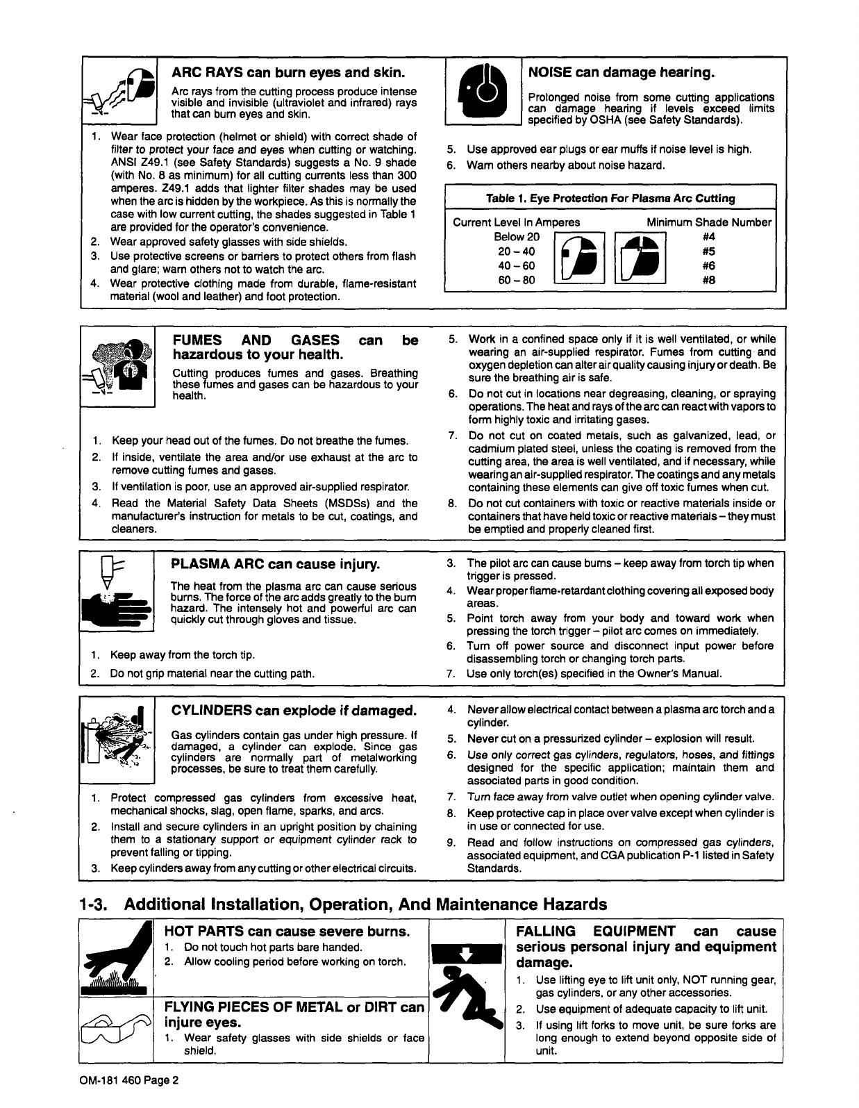
Table
1.
Eye
Protection
For
Plasma
Arc
Cutting
Current
Level
In
Amperes
Minimum
Shade
Number
Below
20
I
#4
2040
I
#5
4060
I
#6
6080
I
_______
_________
_________
#8
1.
2.
PLASMA
ARC
can
cause
injury.
The
heat
from
the
plasma
arc
can
cause
serious
hazard.
The
intensely
hot
and
powerful
arc
can
burns.
The
force
of
the
arc
adds
greatly
to
the
bum
quickly
cut
through
gloves
and
tissue.
1.
Keep
away
from
the
torch
tip.
2.
Do
not
grip
material
near
the
cutting
path.
3.
4
~
5.
6.
7.
The
pilot
arc
can
cause
bums
keep
away
from
torch
tip
when
trigger
is
pressed.
Wear
properflame-retardantclothing
covering
all
exposed
body
areas.
Point
torch
away
from
your
body
and
toward
work
when
pressing
the
torch
trigger
pilot
arc
comes
on
immediately.
Turn
off
power
source
and
disconnect
input
power
before
disassembling
torch
or
changing
torch
parts.
Use
only
torch(es)
specified
in
the
Owners
Manual.
1.
2.
7.
8.
1-3.
Additional
Installation,
Operation,
And
Maintenance
Hazards
FLYING
PIECES
OF
METAL
or
DIRT
can
injure
eyes.
1.
Wear
safety
glasses
with
side
shields
or
face
shield.
OM-181
460
Page
2

FIRE
OR
EXPLOSION
can
result
from
placing
unit
on,
over,
or
near
combustible
surfaces.
1.
Do
not
locate
unit
on,
over,
or
near
combustible
surfaces.
2.
Do
not
install
unit
near
flammables.
MOVING
PARTS
can
cause
injury.
1.
Keep
away
from
moving
parts
such
as
fans.
2.
Keep
all
doors,
panels,
covers,
and
guards
closed
and
securely
in
place.
STATIC
ELECTRICITY
can
damage
parts
on
circuit
boards.
1.
Put
on
grounded
wrist
strap
BEFORE
handling
boards
or
parts.
2.
Use
proper
static-proof
bags
and
boxes
to
store,
move,
or
ship
PC
boards.
OVERUSE
can
cause
OVERHEATED
EQUIPMENT.
Allow
cooling
period.
Reduce
amperage
(thickness)
or
reduce
duty
cycle
before
starting
to
cut
again.
Follow
rated
duty
cycle.
HIGH-FREQUENCY
RADIATION
interfere
with
radio
navigation,
services,
computers,
communications
equipment.
1.
Have
only
qualified
persons
familiar
with
electronic
equipment
perform
this
installation.
2.
The
user
is
responsible
for
having
a
qualified
electrician
promptly
correct
any
interference
problem
resulting
from
the
installation.
3.
If
notified
by
the
FCC
about
interference,
stop
using
the
equipment
at
once.
4.
Have
the
installation
regularly
checked
and
maintained.
5.
Keep
high.frequency
source
doors
and
panels
tighfly
shut,
keep
spark
gaps
at
correct
setting,
and
use
grounding
and
shielding
to
minimize
the
possibility
of
interference.
MAGNETIC
FIELDS
FROM
HIGH
CURRENTS
can
affect
pacemaker
operation.
1.
Pacemaker
wearers
keep
away.
2.
Wearers
should
consult
their
doctor
before
going
near
plasma
arc
cutting
operations.
SIGNIFICANT
DC
VOLTAGE
exists
after
removal
of
input
power
on
inverters.
1.
Turn
Oft
inverter,
disconnect
input
power,
and
discharge
input
capacitors
according
to
instructions
in
Maintenance
Section
before
touching
any
parts.
1-4.
Principal
Safety
Standards
1-5.
EMF
Information
A
can
safety
and
=4
Safety
in
Welding
and
Cutting,
ANSI
Standard
Z49.
1,
from
Ameri
can
Welding
Society,
550
N.W.
LeJeune
Rd,
Miami
FL
33126
Safety
and
Health
Standards,
OSHA
29
CFR
1910,
from
Superin
tendent
of
Documents,
U.S.
Government
Printing
Office,
Washing
ton,
D.C.
20402.
Recommended
Practices
for
Plasma
Arc
Cutting,
American
Weld
ing
Society
Standard
AWS
C5.2,
from
American
Welding
Society,
550
N.W.
LeJeune
Rd,
Miami,
FL
33126
Recommended
Safe
Practices
for
the
Preparation
for
Welding
and
Cutting
of
Containers
That
Have
Held
Hazardous
Substances,
American
Welding
Society
Standard
AWS
F4.1,
from
American
Welding
Society,
550
N.W.
LeJeune
Rd, Miami,
FL
33126
National
Electrical
Code,
NFPA
Standard
70,
from
National
Fire
Protection
Association,
Batterymarch
Park,
Quincy,
MA
02269.
Safe
Handling
of
Compressed
Gases
in
Cylinders,
CGA
Pamphlet
P-i,
from
Compressed
Gas
Association,
1235
Jefferson
Davis
Highway,
Suite
501,
Arlington,
VA
22202.
Code
for
Safety
in
Welding
and
Cutting,
CSA
Standard
Wi
17.2,
from
Canadian
Standards
Association,
Standards
Sales,
178
Rex-
dale
Boulevard,
Rexdale,
Ontario,
Canada
M9W
1
R3.
Safe
Practices
For
Occupation
And
Educational
Eye
And
Face
Pro
tection,
ANSI
Standard
Z87.i,
from
American
National
Standards
Institute,
1430
Broadway,
New
York,
NY
10018.
CuttingAnd
Welding
Processes,
NFPA
Standard
51
B,
from
Nation
al
Fire
Protection
Association,
Batterymarch
Park,
Quincy,
MA
02269.
Considerations
About
Welding
And
The
Effects
Of
Low
Frequency
Electric
And
Magnetic
Fields
The
following
is
a
quotation
from
the
General
Conclusions
Section
of
the
U.S.
Congress,
Office
of
Technology
Assessment,
Biological
Effects
of
Power
Frequency
Electric
&
Magnetic
Fields
Background
Paper,
OTA-BP-E-53
(Washington,
DC:
U.S.
Government
Printing
Office,
May
1989):
.
.
.
there
is
now
a
very
large
volume
of
scientific
findings
based
on
experiments
at
the
cellular
level
and
from
studies
with
animals
and
people
which
clearly
establish
that
low
frequency
magnetic
fields
can
interact
with,
and
produce
changes
in,
biological
systems.
While
most
of
this
work
is
of
very
high
quality,
the
results
are
complex.
Current
scientific
understanding
does
not
yet
allow
us
to
interpret
the
evidence
in
a
single
coherent
framework.
Even
more
frustrating,
it
does
not
yet
allow
us
to
draw
definite
conclusions
about
questions
of
possible
risk
or
to
offer
clear
science-based
advice
on
strategies
to
minimize
or
avoid
potential
risks.
To
reduce
magnetic
fields
in
the
workplace,
use
the
following
procedures:
1.
Keep
cables
close
together
by
twisting
or
taping
them.
2.
Arrange
cables
to
one
side
and
away
from
the
operator.
3.
Do
not
coil
or
drape
cables
around
the
body.
4.
Keep
welding
power
source
and
cables
as
far
away
as
practical.
5.
Connect
work
clamp
to
workpiece
as
close
to
the
weld
as
possible.
About
Pacemakers:
The
above
procedures
are
also
recommended
for
pacemaker
wearers.
Consult
your
doctor
for
complete
information.
OM-181
460
Page
3
2-1.
Selecting
A
Location
SECTION
2-
iNSTALLATION
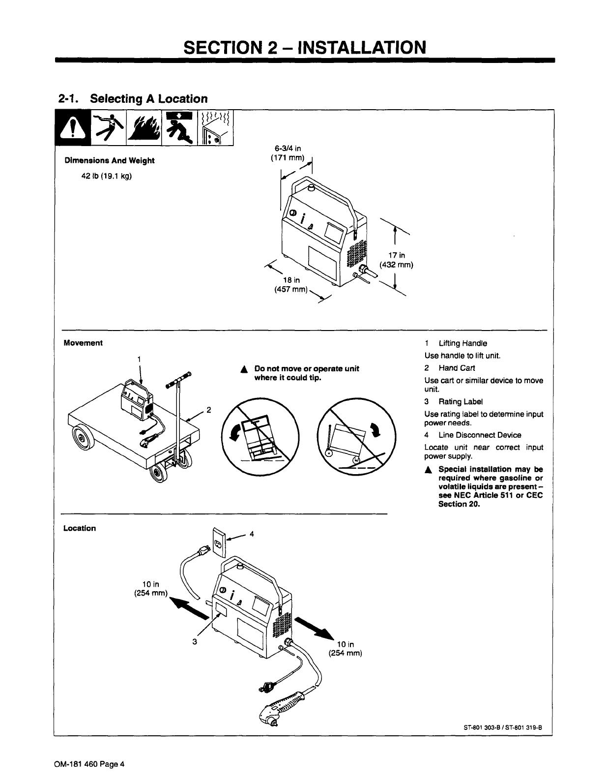
Dimensions
And
Weight
42
lb
(19.1
kg)
17
in
(432
mm)
A
Do
not
move
or
operate
unit
where
it
could
tip.
lOin
(254
mm)
1
Lifting
Handle
Use
handle
to
lift
unit.
2
Hand
Cart
Use
cart
or
similar
device
to
move
unit.
3
Rating
Label
Use
rating
label
to
determine
input
power
needs.
4
Line
Disconnect
Device
Locate
unit
near
correct
input
power
supply.
A
Special
installation
may
be
required
where
gasoline
or
volatile
liquids
are
present
see
NEC
Article
511
or
CEC
Section
20.
ST-801
303-B
/
ST-801
319-B
Movement
18
in
(457
mm)
Location
OM-181
460
Page
4
2-2.
Connecting
Work
Clamp
And
Gas/Air
Supply
2-3.
Installing
Alternative
Plug
Use
only
clean
and
dry
gas/air
with
70
to
150
psi
(483
to
1034
kPa)
pressure.
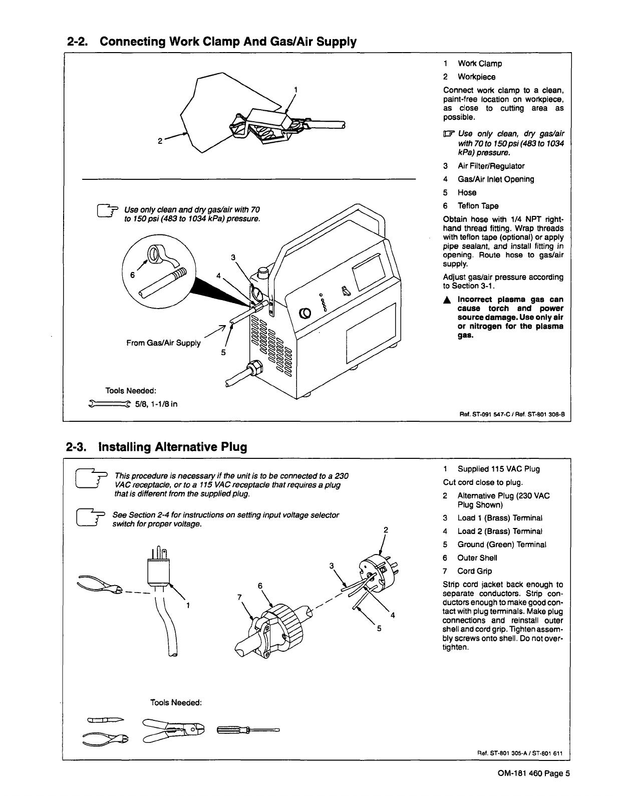
1
Work
Clamp
2
Workpieco
Connect
work
clamp
to
a
clean,
paint-free
location
on
workpiece,
as
close
to
cutting
area
as
possible.
~
Use
only
clean,
diy
gas/air
with
70
to
150
psi
(483
to
1034
kPa)
pressure.
3
Air
Filter/Regulator
4
Gas/Air
Inlet
Opening
5
Hose
6
Teflon
Tape
Obtain
hose
with
1/4
NPT
right-
hand
thread
fitting.
Wrap
threads
with
teflon
tape
(optional)
or
apply
pipe
sealant,
and
install
fitting
in
opening.
Route
hose
to
gas/air
supply.
Adjust
gas/air
pressure
according
to
Section
3-1.
A
Incorrect
plasma
gas
can
cause
torch
and
power
source
damage.
Use
only
air
or
nitrogen
for
the
plasma
gas.
Ref.
51-091
547-C
I
Ref.
ST-SQl
306-6
From
Gas/Air
Supply
Tools
Needed:
_
5/8,1-1/8in
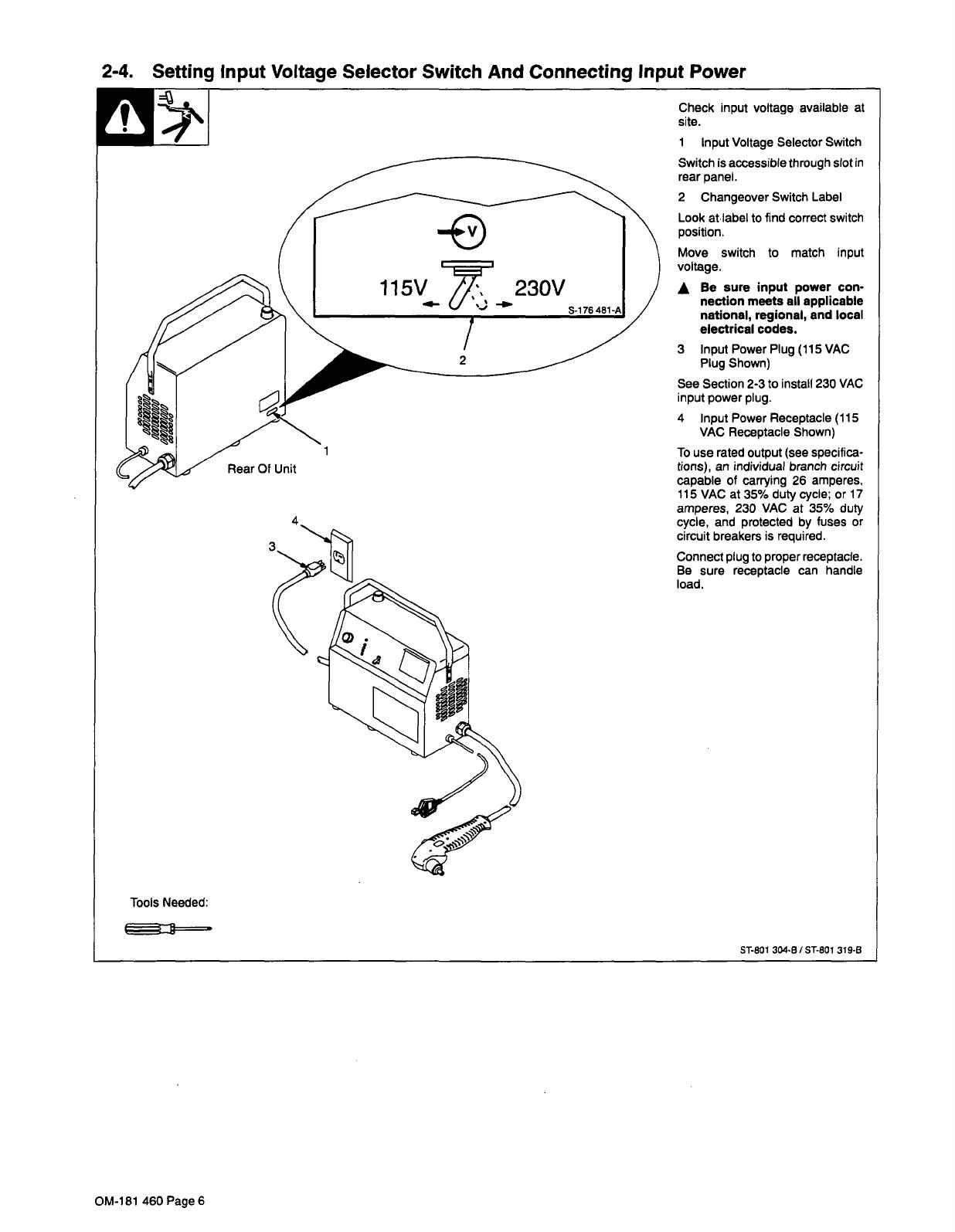
This
procedure
is
necessary
if
the
unit
is
to
be
connected
to
a
230
VAC
receptacle,
or
to
a
115
VAC
receptacle
that
requires
a
plug
that
is
different
from
the
supplied
plug.
See
Section
2-4
for
instructions
on
setting
input
voltage
selector
switch
for
proper
voltage.
1
Supplied
115
VAC
Plug
Cut
cord
close
to
plug.
2
Alternative
Plug
(230
VAC
Plug
Shown)
3
Load
1
(Brass)
Terminal
3
6
4
Load
2
(Brass)
Terminal
7
5
Ground
(Green)
Terminal
6
Outer
Shell
7
Cord
Gnp
4
5
Strip
cord
jacket
back
enough
to
separate
conductors.
Strip
con
ductors
enough
to
make
good
con
tact
with
plug
terminals.
Make
plug
connections
and
reinstall
outer
shell
and
cord
grip.
Tighten
assem
bly
screws
onto
shell.
Do
not
over-
tighten.
Tools
Needed:
~ef.
ST-801
305-A
I
ST-801
611
OM-181
460
Page
5
2-4.
Setting
Input
Voltage
Selector
Switch
And
Connecting
Input
Power
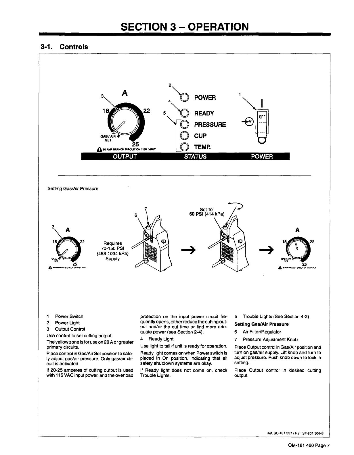
Connect
plug
to
proper
receptacle.
Be
sure
receptacle
can
handle
site.
Check
input
voltage
available
at
1
Input
Voltage
Selector
Switch
Switch
is
accessible
through
slot
in
rear
panel.
-
115V~.
2
Changeover
Switch
Label
Look
at
label
to
find
correct
switch
position.
Move
switch
to
match
input
voltage.
A
Be
sure
input
power
con
nection
meets
all
applicable
national,
regional,
and
local
electrical
codes.
Rear
Of
Unit
3
Input
Power
Plug
(115
VAC
Plug
Shown)
See
Section
2-3
to
install
230
VAC
input
power
plug.
4
Input
Power
Receptacle
(115
VAC
Receptacle
Shown)
To
use
rated
output
(see
specifica
tions),
an
individual
branch
circuit
capable
of
carrying
26
amperes.
115
VAC
at
35%
duty
cycle;
or
17
amperes,
230
VAC
at
35%
duty
cycle,
and
protected
by
fuses
or
circuit
breakers
is
required.
load.
Tools
Needed:
51-801
304.B/S1-801
319-6
OM-181
460
Page
6
3-1.
Controls
SECTION
3-
OPERATION
POWER
~
READY
~ro
PRESSURE
CUP
LO
Requires
70-1
50
PSI
(483-1034
kPa)
Supply
1
Power
Switch
2
Power
Light
3
Output
Control
Use
control
to
set
cutting
output.
The
yellow
zone
is
for
use
on
20
A
orgreater
primary
circuits.
Place
control
in
Gas/Air
Set
position
to
safe
ly
adjust
gas/air
pressure.
Only
gas/air
cir
cuit
is
activated.
If
20-25
amperes
of
cutting
output
is
used
with
115
VAC
input
power,
and
the
overload
protection
on
the
input
power
circuit
fre
quently
opens,
either
reduce
the
cutting
out
put
and/or
the
cut
time
or
find
more
ade
quate
power
(see
Section
2-4).
4
Ready
Light
Use
light
to
tell
if
unit
is
ready
for
operation.
Ready
light
comes
on
when
Power
switch
is
placed
in
On
position,
indicating
that
all
safety
shutdown
systems
are
okay.
If
Ready
light
does
not
come
on,
check
Trouble
Lights.
5
Trouble
Lights
(See
Section
4-2)
Setting
Gas/Air
Pressure
6
Air
Filter/Regulator
7
Pressure
Adjustment
Knob
Place
Output
control
in
Gas/Air
position
and
turn
on
gas/air
supply.
Lift
knob
and
turn
to
adjust
pressure.
Push knob
down
to
lock
in
setting.
Place
Output
control
in
desired
cutting
output.
Ref.
SC~1
81
337/Ref.
ST-801
306-B
A
1
82
Ak~
BRANOI
0IRWTC~
1I~
t*VT
-e
OUTPUT
STATUS
POWER
Setting
Gas/Air
Pressure
7
60
A
-4
a
~
l~ara~
OM-181
460
Page
7

3-2.
Duty
Cycle
And
Overheating
3-3.
Cutting
Speed
~s
~s
~s
~
MAX
OUTPUT
SETTN
P~iI~I
20
AMP
OUTPUT
SETTING
~-.
G
~
~
E
T
~-..
EE
E
GUN
35%
Duty
Cycle
At
25
Amperes
Duty
Cycle
is
percentage
of
10
minutes
that
unit
can
cut
at
rated
load
without
overheating.
3-1/2
Minutes
Cutting
If
unit
overheats,
thermostat(s)
opens,
output
stops,
Temperature
trouble
light
goes
On,
and
cooling
fan
runs.
Wait
fifteen
minutes
for
unit
to
cool
or
temperature
light
to
go
off.
Reduce
amperage
or
duty
cycle
before
cutting
or
gouging.
6-1/2
Minutes
Resting
UNIT
A
Exceeding
duty
cycle
can
damage
unit
and
void
warranty.
115
VAC
Input
Power:
35%
Duty
Cycle
At
20
Amperes,
20
Ampere
Input
Circuit
115
VAC
Input
Power:
35%
Duty
Cycle
At
25
Amperes,
30
Ampere
Input
Circuit
230
VAC
Input
Power:
35%
Duty
Cycle
At
25
Amperes
Overheating
3-1/2
Minutes
Cutting
6-1/2
Minutes
Resting
A
sdutyl
5/95
Recommended
production
cutting
speed
vs.
material
thickness
is
approximately
10
ipm
at
5/16
in
mild
steel
thickness
at
max
setting.
70
The
cutting
speed
curves
show
the
recommended
maximum
cutting
speed
capabilities
of
the
power
source
and
torch
for
mild
steel
of
various
thickness.
40
z
z
a
UJ
uJ
0~
LI)
I
U
30
Cut
at
speeds
below
the
lines
shown
to
avoid
poor
cuts
and
torch
wear.
20
10
0
005
0.1
0.15
02
0.25
0.3
035
0.4
MATERIAL
THICKNESS
IN.
ST.179
507
OM-181
460
Page
8
SECTION
4-
MAINTENANCE
&
TROUBLESHOOTING
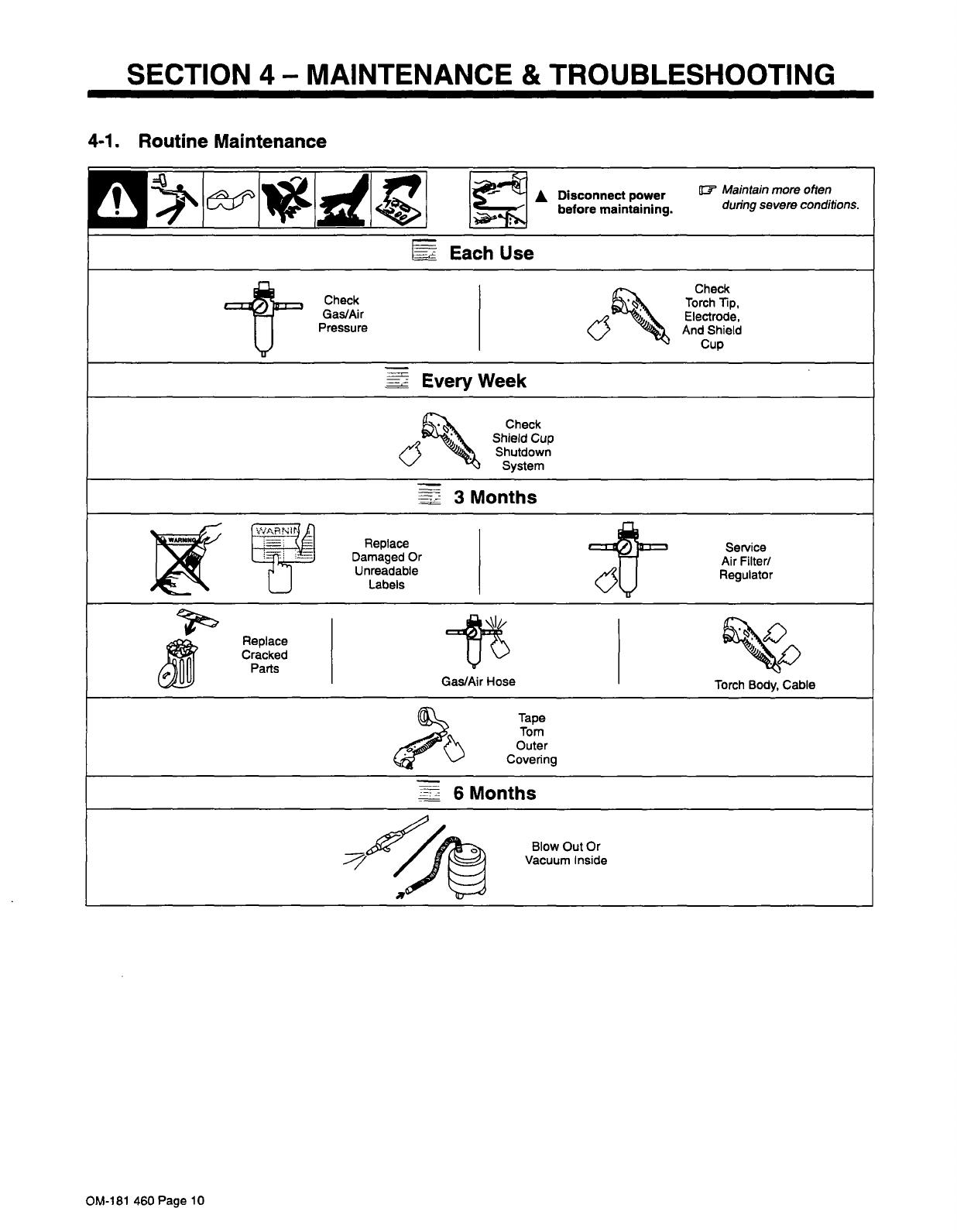
4-1.
Routine
Maintenance
OM-181
460
Page
10
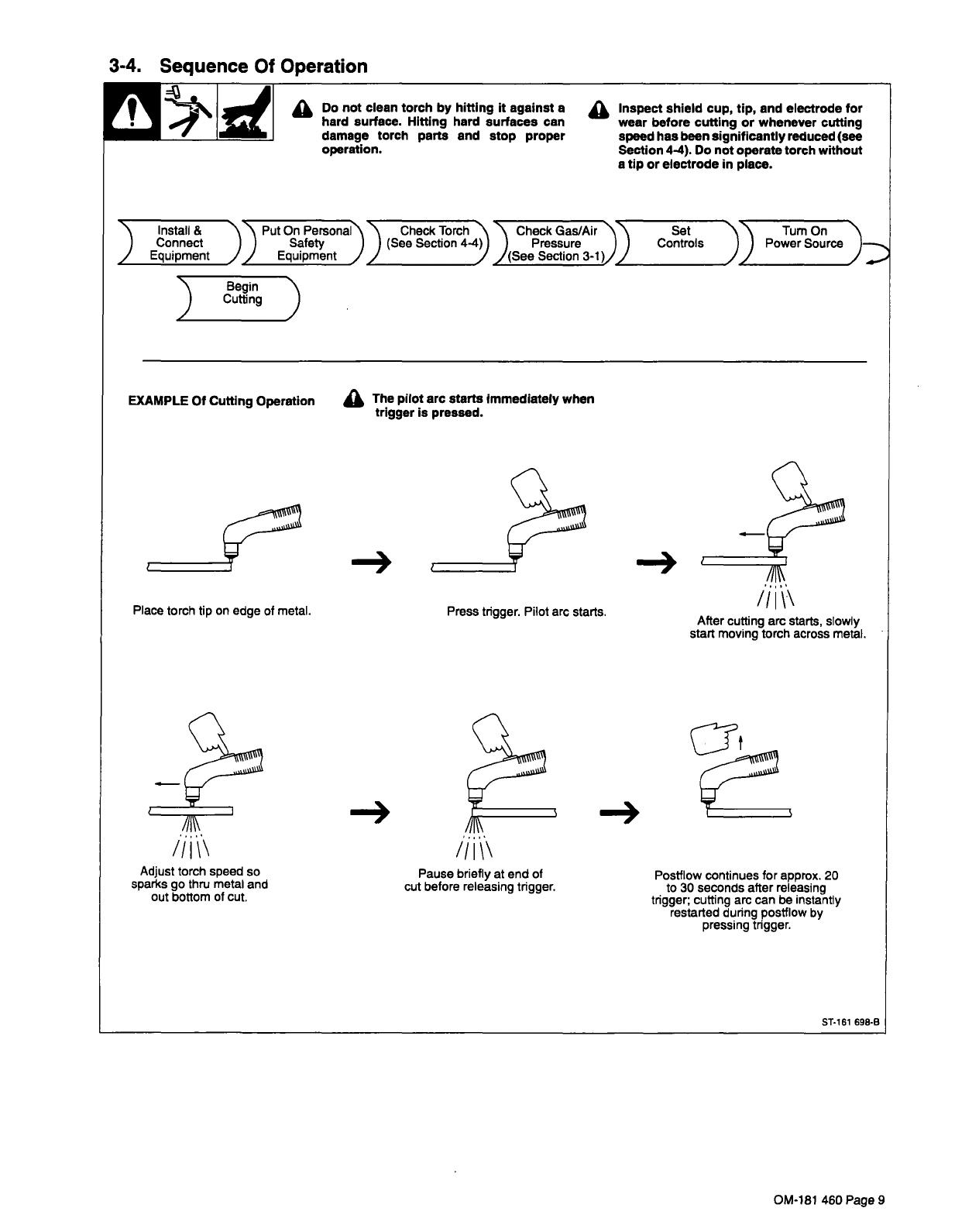
3-4.
Sequence
Of
Operation
Do
not
clean
torch
by
hitting
it
against
a
~
Inspect
shield
cup,
tip,
and
electrode
for
!
4~\
1d~
hard
surface.
Hitting
hard
surfaces
can
wear
before
cutting
or
whenever
cutting
damage
torch
parts
and
stop
proper
speed
has
been
significantly
reduced
(see
operation.
Section
4.4).
Do
not
operate
torch
without
a
tip
or
electrode
in
place.
Turn
On
Connect
)
)
Safety
)
)
(See
Section
4-4)
Install
&
~\
\
Put
On
Per~~\\
Check
Torch
)
~\
Check
Gas/Air
Set
)
Power
So~~~)
J
Equipment
JJ
Equipment
~
,
Pressure
I
Controls
_______________
_______________
_______________
J(See
Section
3-1)
_______________
Begin
~\
)
Cutting
)
EXAMPLE
Of
Cutting
Operation
~
The
pilot
arc
starts
immediately
when
trigger
is
pressed.
I
Place
torch
tip
on
edge
of
metal.
Press
trigger.
Pilot
arc
starts.
After
cutting
arc
starts,
slowly
start
moving
torch
across
metal.
~
/1
/1
Adjust
torch
speed
so
Pause
briefly
at
end
of
Postf
low
continues
for
approx.
20
sparks
go
thru
metal
and
cut
before
releasing
trigger,
to
30
seconds
after
releasing
out
bottom
of
cut.
tngger;
cutting
arc
can
be
instantly
restarted
during
postflow
by
pressing
trigger.
ST-161
698-B
OM-181
460
Page
9
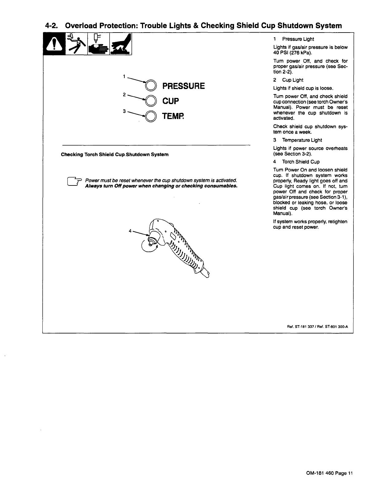
4-2.
Overload
Protection:
Trouble
Lights
&
Checking
Shield
Cup
Shutdown
System
PRESSURE
~
CUP
~T~O
TEMR
1
Pressure
Light
Lights
if
gas/air
pressure
is
below
40
PSI
(276
kPa).
Turn
power
Off,
and
check
for
proper
gas/air
pressure
(see
Sec
tion
2-2).
2
Cup
Light
Lights
if
shield
cup
is
loose.
Turn
power
Off,
and
check
shield
cup
connection
(see
torch
Owners
Manual).
Power
must
be
reset
whenever
the
cup
shutdown
is
activated.
Check
shield
cup
shutdown
sys
tem
once
a
week.
3
Temperature
Light
Checking
Torch
Shield
Cup.Shutdown
System
Power
must
be
reset
whenever
the
cup
shutdown
system
is
activated.
Always
turn
Off
power
when
changing
or
checking
consumables.
4
Lights
if
power
source
overheats
(see
Section
3-2).
4
Torch
Shield
Cup
Turn
Power
On
and
loosen
shield
cup.
If
shutdown
system
works
properly,
Ready
light
goes
oft
and
Cup
light
comes
on.
If
not,
turn
power
Off
and
check
for
proper
gas/airpressure
(see
Section
3-1),
blocked
or
leaking
hose,
or
loose
shield
cup
(see
torch
Owners
Manual).
If
system
works
properly,
retighten
cup
and
reset
power.
Ref.
ST-181
337/Ref.
ST-801
300-A
OM-181
460
Page
11
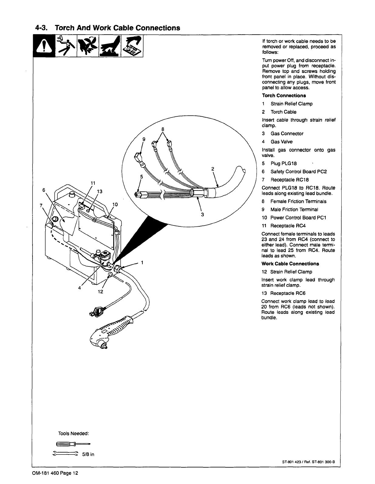
4-3.
Torch
And
Work
Cable
Connections
Tools
Needed:
5/8in
If
torch
or
work
cable
needs
to
be
removed
or
replaced,
proceed
as
follows:
Turn
power
Off,
and
disconnect
in
put
power
plug
from
receptacle.
Remove
top
and
screws
holding
front
panel
in
place.
Without
dis
connecting
any
plugs,
move
front
panel
to
allow
access.
Torch
Connections
1
Strain
Relief
Clamp
2
Torch
Cable
Insert
cable
through
strain
relief
clamp.
3
Gas
Connector
4
Gas
Valve
Install
gas
connector
onto
gas
valve.
5
Plug
PLG18
6
Safety
Control
Board
PC2
7
Receptacle
RC1
8
Connect
PLG18
to
RC18.
Route
leads
along
existing
lead
bundle.
8
Female
Friction
Terminals
9
Male
Friction
Terminal
10
Power
Control
Board
PCi
11
Receptacle
RC4
Connect
female
terminals
to
leads
23
and
24
from
RC4
(connect
to
either
lead).
Connect
male
termi
nal
to
lead
25
from
RC4.
Route
leads
as
shown.
Work
Cable
Connections
12
Strain
Relief
Clamp
Insert
work
clamp
lead
through
strain
relief
clamp.
13
Receptacle
RC6
Connect
work
clamp
lead
to
lead
20
from
RC6
(leads
not
shown).
Route
leads
along
existing
lead
bundle.
ST-801
423
I
Ref.
ST-801
300-B
OM-181
460
Page
12

4-4.
Checking/Replacing
Retaining
Cup,
Tip,
And
Electrode
~
Overtightening
will
strip
threads.
Do
not
overtighten
electrode,
tip,
and
retaining
cup
during
as
sembly.
Do
not
cross-thread
parts
causing
stripping.
Use
care
during
torch
assembly
and
parts
replacement.
Inspect
shield
cup,
tip,
and
electrode
for
wear
before
cutting
or
whenever
cutting
speed
has
been
significantly
reduced.
Do
not
operate
torch
without
a
tip
or
electrode
In
place.
Be
sure
to
use
genuine
replacement
parts.
A
good
practice
is
to
replace
both
the
tip
and
electrode
at
the
same
time.
2
Tip
3
Opening
Turn
Off
power
source,
and
remove
input
power
plug
from
receptacle
before
checking
torch
parts.
The
word
~fivnr
on
swirl
ring
must
face
away
from
torch
body.
Make
sure
swirl
ring
is
clean
of
any
debris
and
no
holes
are
ob
structed.
Remove
tip.
Check
tip,
and
replace
if
opening
is
deformed
or
50%
oversize.
If
inside
of
tip
is
not
clean
and
bright,
clean
with
steel
wool.
Be
sure
to
remove
any
pieces
of
steel
wool
afterwards.
4
Electrode
Check
electrode.
If
center
has
a
pit
more
than
a
1/16
in
(2
mm)
deep,
remove
and
replace
electrode
us
ing
supplied
wrench.
Do
not
overtighten.
7
Plunger
Area
Check
this
area
for
any
debris
or
foreign
material.
Clean
out
if
nec
essary.
Carefully
reassemble
parts
in
re
verse
order.
Swirl
ring
must
be
in
stalled
with
word
front
facing
away
from
torch
body.
Turn
Off
power
source.
1
Retaining
Cup
Remove
retaining
cup.
Check
re
taining
cup
for
cracks,
and
replace
if
necessary.
Make
sure
this
area
is
clean
of
any
debris.
5
Swirl
Ring
Remove
swirl
ring.
Check
nng,
and
replace
if
side
holes
are
plugged.
6
0-Ring
Check
0-rings
on
torch.
If
needed,
coat
with
thin
film
of
supplied
lubri
cant.
Replace
if
damaged.
Tools
Needed:
(Supplied)
ST-801
301
/ST~801
139
OM-181
460
Page
13
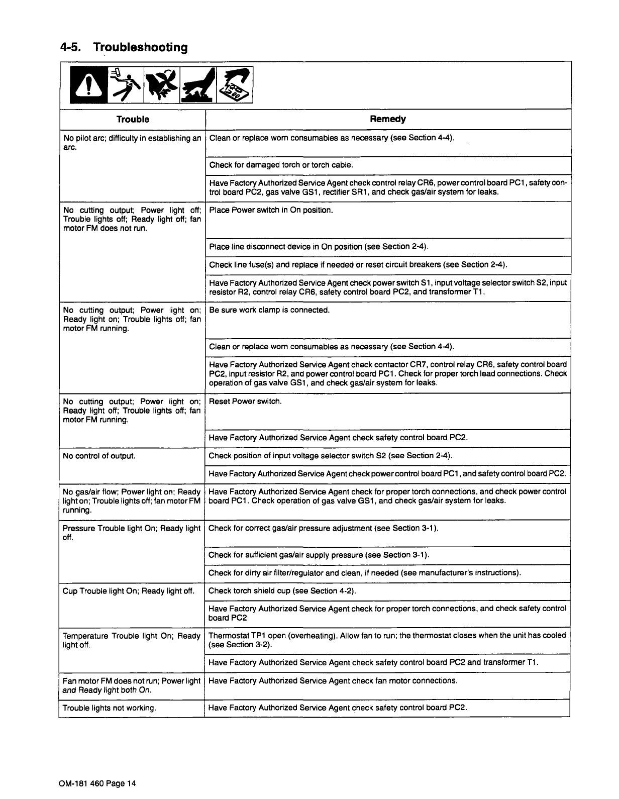
4-5.
Troubleshooting
Trouble
Remedy
No
pilot
arc;
difficulty
in
establishing
an
arc.
Clean
or
replace
worn
consumables
as
necessary
(see
Section
4-4).
Check
for
damaged
torch
or
torch
cable.
Have
Factory
Authorized
Service
Agent
check
control
relay
CR6,
power
control
board
PCi
,
safety
con
trol
board
PC2,
gas
valve
GS1
rectifier
SRi,
and
check
gas/air
system
for
leaks.
No
cutting
output;
Power
light
off;
Trouble
lights
off;
Ready
light
oft;
fan
motor
FM
does
not
run.
Place
Power
switch
in
On
position.
Place
line
disconnect
device
in
On
position
(see
Section
2-4).
Check
line
fuse(s)
and
replace
if
needed
or
reset
circuit
breakers
(see
Section
2-4).
Have
Factory
Authorized
Service
Agent
check
power
switch
Si,
input
voltage
selector
switch
S2,
input
resistor
R2,
control
relay
CR6,
safety
control
board
PC2,
and
transformer
Ti.
No
cutting
output;
Power
light
on;
Ready
light
on;
Trouble
lights
off;
fan
motor
FM
running.
Be
sure
work
clamp
is
connected.
Clean
or
replace
worn
consumables
as
necessary
(see
Section
4-4).
Have
Factory
Authorized
Service
Agent
check
contactor
CR7,
control
relay
CR6,
safety
control
board
PC2,
input
resistor
R2,
and
power
control
board
PCi.
Check
for
proper
torch
lead
connections.
Check
operation
of
gas
valve
GS1,
and
check
gas/air
system
for
leaks.
No
cutting
output;
Power
light
on;
Ready
light
off;
Trouble
lights
oft;
fan
motor
FM
running.
Reset
Power
switch.
Have
Factory
Authorized
Service
Agent
check
safety
control
board
PC2.
No
control
of
output.
Check
position
of
input
voltage
selector
switch
S2
(see
Section
2-4).
Have
Factory
Authorized
Service
Agent
check
power
control
board
PCi
,and
safety
control
board
PC2.
No
gas/air
flow;
Power
light
on;
Ready
light
on;
Trouble
lights
off;
fan
motor
FM
running.
Have
Factory
Authorized
Service
Agent
check
for
proper
torch
connections,
and
check
power
control
board
PCi.
Check
operation
of
gas
valve
GS1,
and
check
gas/air
system
for
leaks.
Pressure
Trouble
light
On;
Ready
light
off.
Check
for
correct
gas/air
pressure
adjustment
(see
Section
3-i).
Check
for sufficient
gas/air
supply
pressure
(see
Section
3-i).
Check
for
dirty
air
filter/regulator
and
clean,
if
needed
(see
manufacturers
instructions).
Cup
Trouble
light
On;
Ready
light
off.
Check
torch
shield
cup
(see
Section
4-2).
Have
Factory
Authorized
Service
Agent
check
for
proper
torch
connections,
and
check
safety
control
board
PC2
Temperature
Trouble
light
On;
Ready
light
off.
Thermostat
TP1
open
(overheating).
Allow
fan
to
run;
the
thermostat
closes
when
the
unit
has
cooled
(see
Section
3-2).
Have
Factory
Authorized
Service
Agent
check
safety
control
board
PC2
and
transformer
Ti.
Fan
motor
FM
does
not
run;
Power
light
and
Ready
light
both
On.
Have
Factory
Authorized
Service
Agent
check
fan
motor
connections.
Trouble
lights
not
working.
Have
Factory
Authorized
Service
Agent
check
safety
control
board
PC2.
OM-18i
460
Page
14
cJ
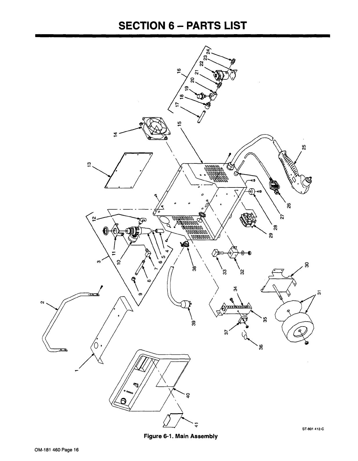
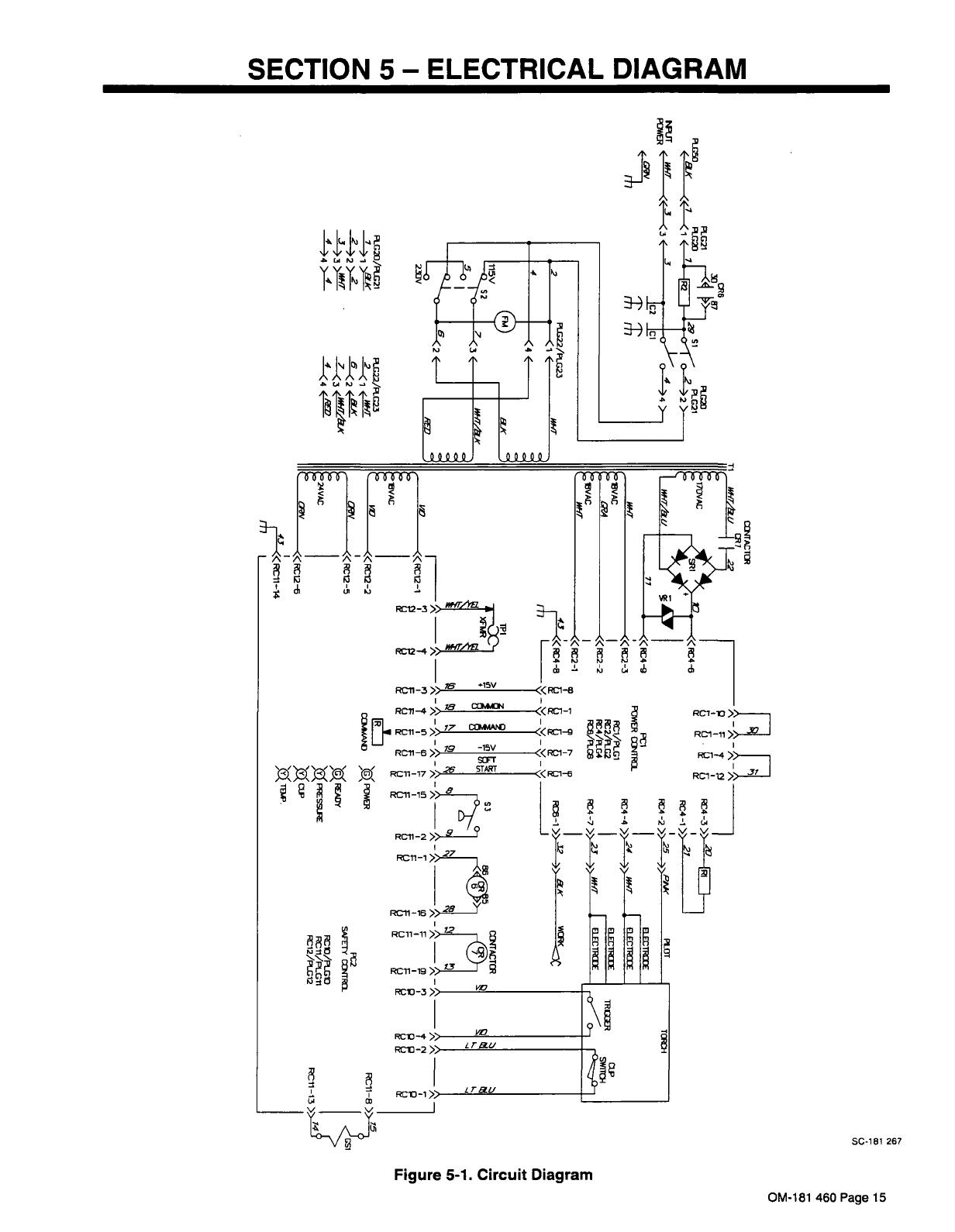
SECTION
6-
PARTS
LIST
Co
0
Figure
6-1.
Main
Assembly
Co
cJ
0)
cJ
0
C,)
ST-aol
412-C
OM-181
460
Page
16
6
-J
C-)
I
C)
w
-J
U
U)
z
0
p
C.)
w
C/)
~jr
~
3
POWER
CD
CJ
CD
o
Pci
POWER
~
Rci/r&Gl
r~2/nr~2
IW~4/P~G4
F~/ft~
PLG2O/P1621
-~-~3>~
R022/RG23
-~-<24~
~
(0
N
In
c~u
E
1~
a)
a
U
I
0
a)
L1~
PF~S9J~
PC2
ERFETY
O~1
POIJ/P(~G1O
Rcii/PLG1I
PO12/F~G12
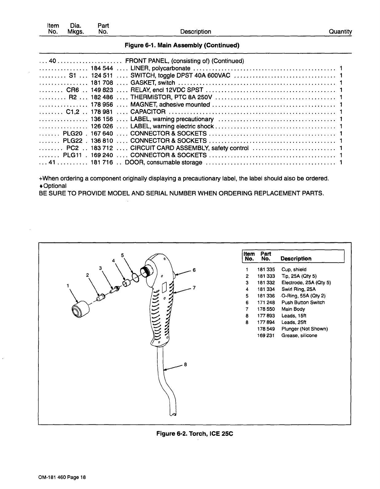
Item
Dia.
Part
No.
Mkgs.
No.
Si...
CR6..
R2...
C1,2..
PLG2O
PLG22
PC2..
PLG11
124
511
181
708
149
823
182
486
178
956
178
981
136 156
126
026
167
640
136
810
183
712
169240
181
716
+When
ordering
a
component
originally
displaying
a
precautionary
label,
the
label
should
also
be
ordered.
Optional
BE
SURE
TO
PROVIDE
MODEL
AND
SERIAL
NUMBER
WHEN
ORDERING
REPLACEMENT
PARTS.
Item
Part
No.
No.
Description
Figure
6-2.
Torch,
ICE
25C
Description
Figure
6-1.
Main
Assembly
(Continued)
Quantity
40
FRONT
PANEL,
(consisting
of)
(Continued)
184
544
....
LINER,
polycarbonate
1
SWITCH,
toggle
DPST
40A
600VAC
1
GASKET
switch
1
RELAY,
end
12VDC
SPST
1
THERMISTOR,
PTC
8A
250V
1
MAGNET,
adhesive
mounted
1
CAPACITOR
1
LABEL,
warning
precautionary
1
LABEL,
warning
electric
shock
1
CONNECTOR
&
SOCKETS
1
CONNECTOR
&
SOCKETS
1
CIRCUIT
CARD
ASSEMBLY,
safety
control
1
CONNECTOR
&
SOCKETS
1
DOOR,
consumable
storage
1
5
3
6
1
181
335
Cup,
shield
2
181
333
Tip,
25A(Qty
5)
3
181
332
Electrode,
25A
(Qty
5)
7
4
181
334
Swirl
Ring,
25A
5
181
336
0-Ring,
55A
(Qty
2)
6
171
248
Push
Button
Switch
7
178550
Main
Body
8
177893
Leads,l5tt
8
177894
Leads,25ft
178
549
Plunger
(Not
Shown)
169
231
Grease,
silicone
8
OM-181
460
Page
18

Item
Dia.
Part
No.
Mkgs.
No.
Description
Quantity
Figure
6-1.
Main
Assembly
COVER,
top
1
HANDLE,
lifting
1
REGULATOR
ASSEMBLY,
(consisting
of)
1
HOSE,
SAE
.187
ID
x
.410
OD
x
6.500
1
FITTING,
brs
barbed
fern
3/i6tbg
x
1/8NPT
1
REGULATOR/FILTER,
250
PSIG
in
100
PSIG
rnax
out
1
FITTING,
pipe
brs
elbow
st
i/4NPT
1
FITTING,
pipe
brs
nipple
L
1/4NPT
x
2.500
1
FITTING,
pipe
brs
coupling
1/4NPT
1
FITTING,
pipe
brs
plug
shhd
1/4NPT
1
GAUGE,
pressure
air
0-160
PSI
1/8NPT
1
BRACKET,
rntg
air
filter/regulator
1
FITTING,
plstc
Qdisc
elbow
1/4NPT
x
1/4
OD
tubing
1
CIRCUIT
CARD
ASSEMBLY,
power
control
1
CONNECTOR&
SOCKETS
1
CONNECTOR&SOCKETS
1
CONNECTOR,
rect
1
row
plug
1
CONNECTOR,
rect
skt
20-i4ga
1
STAND-OFF
SUPPORT,
PC
card
3
STAND-OFF,
6-32
x
.437
Ig
4
MOTOR
FAN,
115V
50/60
Hz
31
00RPM
1
CASE,
base/back/sides
1
AIR
VALVE
ASSEMBLY,
(consisting
of)
1
TUBING,
pneurnatic
.250
OD
x
.170
ID
x
13.500
1
FITTING,
plstc
Qdisc
straight
1/8NPT
x
1/4
OD
1
SWITCH,
pressure
air
4OPSI
fixed
1
FITTING,
pipe
brs
tee
1/8NPT
1
FITTING,
pipe
brs
nipple
hex
1/8NPT
1
VALVE,
24VAC
3
way
1/8NPT
5/32
ort
100PSI
1
BRACKET,
valve
1
FITTING,
pipe
brs
adaptor
1/8NPT/.375-24
LH
1
ICE-25C
PLASMA
ARC
CUTTING
TORCH,
15ft
(Fig
6-2)
1
ICE-25C
PLASMA
ARC
CUTTING
TORCH,
25ft
(Fig
6-2)
1
BUSHING,
strain
relief
.455/.629
ID
x
1.ll5mtg
1
CABLE,
work
15ft
(consisting
of)
1
CLAMP,
univ
50A
1
WIRE,
strd
i2ga600V(orderbyft)
l5ft
TUBING,
plstc
PVC
blk
.250
ID
x
.375
OD
x
9.000
1
BUSHING,
strain
relief
.500
ID
x
.465mtg
hole
1
MOUNT,
nprn
6
CONTACTOR,
def
prp
25A
1
P
24VAC
1
BRACKET,
transformer
1
TRANSFORMER,
main
power
115/230
1
BRACKET,
switch
1
SWITCH,
toggle
DPDT
15A
125VAC
1
CONNECTOR&
SOCKETS
1
RESISTOR,
WW
fxd
338W
1.5
ohm
1
BRACKET,
resistor
1
VARISTOR
1
RECTIFIER,
integ
40A
800V
1
CONNECTOR,
clamp
cable
1
CABLE,
poweriofti4ga3/C
1
FRONT
PANEL,
(consisting
of)
1
PANEL,
front
1
KNOB,
pointer
1
NAMEPLATE,
(order
by
model
and
serial
number)
1
OM-181
460
Page
17
1
183161
2
175145
3
175366
4
177347
5
175999
6
174668
7
176518
8
176517
9
602963
118134
10
174783
11
174562
12
176123
13..
PCi
..
184973
PLG1
..
158720
PLG4..
168071
PLG6..
176121
114066
134201
070026
...14...
FM...
088566
15
183162
16
175365
..17
177346
18
176122
19
174670
602965
073655
...22
GSi
..
175827
23
157057
24
175998
25
176499
25
,176822
139041
26
176071
601
222
600
848
176089
27
020577
28
019663
29..
CR7
..
175828
30
175144
.31...
Ti
176500
32
175056
...33...
S2...
011611
PLG21
.
136810
34...
Ri
...
176505
175058
...36
VR1
..
178393
..37
SRi
..
179682
38
010916
..39.
PLG5O
.
181
269
.40
+181
717
174991


 1
1
 2
2
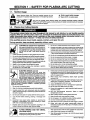 3
3
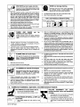 4
4
 5
5
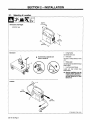 6
6
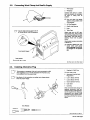 7
7
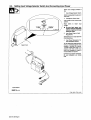 8
8
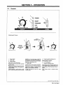 9
9
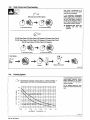 10
10
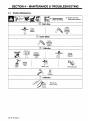 11
11
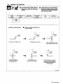 12
12
 13
13
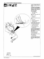 14
14
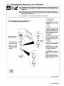 15
15
 16
16
 17
17
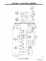 18
18
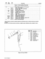 19
19
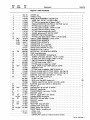 20
20
 21
21
 22
22
 23
23
 24
24


Miller QUICK CUT 3800 Owner's manual
Miller GA-16C1 Owner's manual
Miller I-22A Owner's manual
ESAB Remote Hand Switch Installation guide
Lincoln Electric K2820-1 Installation guide
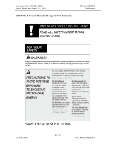 LG Electronics USA BEJV204NTA User manual
Samsung RT2ASKSW User manual
APsystems 25A AC Connector User guide
 Deye SUN Series User manual
GCE 6-PORT CYLINDER REGULATOR Operating instructions
 OQTIQ MagGripCD User manual
HobartWelders AIRFORCE 400 & ICE-27C TORCH Owner's manual
Hobart Welding Products CYBERCUT 1025 User manual


