Drg No. KSRFR350EM-51EM-IS-H
Installation Sheet
Important Information
It is recommended that these luminaires are installed and fitted by a qualified electrician ensuring the
installation complies with current IEE wiring regulations & local building control. These products are designed
for connection to a 240V~50Hz supply.
Any faulty, broken or damaged luminaires should be replaced immediately.
KSR will not accept responsibility for any claims arising from a poor installation.
Please Note: The limited warranty shall be deemed null and void in the following circumstances: Failure by
the installer, end user or any third party to exercise caution to protect any covered product or part from
outside damage, adverse temperature (normal operating ambient temperature 0°C - +35°C), humidity
conditions, fluctuations in the electrical system or physical abuse as well as failure related to workmanship in
the installation of the products or parts.
Installation Procedure
KSR recommends that a sample hole is cut in some scrap material to familiarise yourself with the
installation. Once you are completely satisfied:
Locate the area's suitable to install these luminaires.
Cut a 72mm round hole in the ceiling and ensure sufficient ceiling void without
infringing on joists, water pipes or electrical cables.
Connect the mains supply to the emergency pack/LED Driver as below. Earth terminals are provided for
earth continuity only. The LED driver allows for mains loop in/loop out connections, if not looping through
either of the L,E & N inputs can be used.
Press springs back and push luminaire body into aperture.
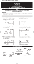
This luminaire is suitable for installations where vapor permeable membranes are installed. Fit this product
as per illustration shown in Fig.1
If you are installing one of the KSR detachable rims remove the standard white rim by pulling the trim off of
the main fitting, do not twist the trim and attach new trim by pushing and clicking it into place. Ensure there
is adequate free air ventilation around the driver and emergency control pack. the head unit can be covered
in mineral wool insulation.
Turn on the mains supply to test the luminaire.
*This downlight is designed with a Isolator switch (Fig.2) to allow for High voltage insulation resistance
testing, without having to remove the luminaire/driver from the circuit just switch all isolation switches to off,
test then switch back to on for normal operation.
An initial 24 hour charge period will be required prior to conducting any emergency lighting tests, thereafter
periodic testing should be carried out in line with current regulations.
*Please note: Depending on the amount of Qr10 fittings on a circuit you may have to upgrade the breaker to
a 'C' or 'D' type due to the way electronic LED drivers start up with higher inrush currents compared to
halogen lighting.
Available Rim Finishes: White, Chrome, Satin Chrome, Brass
Antique Brass, Copper, Black or Stainless Steel
IP65 240VAC~50Hz 8.8W
KSRFRD350EM/351EM 3 Hour Emergency Downlight Qr10 COB
8.8W - 3000K (825 lumens)
LED Wattage/ Colour/Lumens
72mm
85mm 90mm
ØCut outØRim Size Void Depth
Req'd
KSRFRD350EM
8.8W - 4000K (855 lumens)
72mm
85mm 90mm
KSRFRD351EM
Fig. I
90mm min. void depth
Part "B"
BS476
Part 21
Part "E"
(Acoustics)
Part "C"
Compliant
Stops moisture &
air flow through
the luminaire
19.10.2022-PJL
KSR Lighting Aftersales: 023 92 674343
Read these instructions before commencing installation. Please give these instructions to the
owner/occupier after installation to retain for future reference/maintainence.
Important User Advice
Always switch off mains supply before installing/servicing.
*Due to the components used in the driver these are not compatible with earlier versions of the Qr10
downlights and should not be mixed on the same circuit.
This luminaire is suitable for indoor use only and should not be fitted to damp or wet surfaces such as freshly
plastered or painted ceilings.To prevent damage to the driver, do not mix with conventional magnetic ballasts
on the same electrical circuit. At the end of life the luminaire is classed as WEEE under directive 2014/30/EU
and should be disposed of in accordance with local legislation
45mm
124mm
85mm
54mm
27mm
Isolator Switch
Isolates device
from Circuit
Fig. 2
On
Off
Please Note: The isolation switch needs to be in
the On ( I ) position during normal operation
KSR Lighting Ltd, Optimum House, Beeding Close, Southern Cross Trading Estate,
Bognor Regis, West Sussex, PO22 9TS.


