Page is loading ...

Drg No. KSR98123-IS-C
KSR Lighting Ltd, Unit E Hazleton Interchange, Lakesmere Road, Horndean, Hampshire, PO8 9JU
24.01.2022RTG
Installation Sheet KSR98123
Read these instructions before commencing installation. Please give these instructions to the owner/occupier after
installation to retain for future reference/maintainence.
Navara HB
Available finish: Black
IP65 Dimming Microwave Sensor
IP65 220-240VAC~50/60Hz
KSR Lighting Aftersales: 023 92 674343
E-mail: aftersales@ksrlighting.com
These fittings are Class II and do not require to be Earthed
Important Information
It is recommended that these controls are installed and fitted by a qualified electrician
ensuring the installation complies with current IEE wiring regulations & local building
control. These products are designed for connection to a 220-240V~50/60Hz supply.
Any faulty, broken or damaged sensors should be replaced immediately.
KSR will not accept responsibility for any claims arising from a poor installation.
Please Note: The limited warranty shall be deemed null and void in the following circumstances: Failure by the installer, end user or any third
party to exercise caution to protect any covered product or part from outside damage, adverse temperature, humidity conditions, fluctuations in
the electrical system or physical abuse as well as failure related to workmanship in the installation of the products or parts.
Important User Advice
Always switch off mains supply before fitting or servicing.
Do not use Megger or similar high voltage instruments. Due to the fact this control contains electronic components that maybe damaged by
high test voltages, they must be disconnected from the circuit before testing.
To prevent damage to the control, do not mix with conventional magnetic ballasts on the same electrical circuit.
At the end of life the luminaire is classed as WEEE under directive 2014/30/EU and should be disposed of in accordance with local legislation.
Installation Procedure
KSR recommends that you familiarise yourself with the installation. Once you are completely satisfied:
Safely isolate the mains supply.
Locate the area's suitable to install this control on the luminaire (See KSR98120, KSR98121 or KSR98122 for further information).
Avoid the following situations:
Avoid pointing the detector towards objects with highly reflective surfaces, such as mirrors etc.
Avoid metal objects in the line of sight.
Avoid pointing the detector towards objects that may move in the wind, such as curtains, tall plants etc
Install the sensor on to the luminaire.
Connect the wiring as per the instructions supplied with the highbay. If you do not have these please contact KSR for a copy or download from
www.ksrlighting.com
See overleaf for setting options, never remove the cover or adjust the dip switches without safely isolating the mains supply.
Switch on the power and test.
Sensor Specification:
Mains Input - 220~240VAC 50/60Hz
Lux Control - 2, 10, 50 or 2000 Lux
Hold Time - 5s, 30s, 90s, 3min, 5min, 10min, 20min
or 30min
Rated Load - LED 1000W
Halogen 2000W
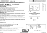
Detection Area - 360°
Detection Range - 50% or 100%
Detection Radius - 10m Max (<24°C)
Stand-by Period - 0s, 10s, 1min, 5min, 10min, 30min,
60min or ∞
Stand-by Dimming Level - 10%, 20%, 30% or 50%
Parasitic Power - 0.5W
Installation Height - 4m~15m
Detection Speed: 0.6~1.5m/s
Working Temperature: -20~+40°C
4-15m
10m10m
59mm
72mm
78mm
700mm

Installation Sheet KSR98123 Wiring
Read these instructions before commencing installation. Please give these instructions to the owner/occupier after
installation to retain for future reference/maintainence.
Drg No. KSR98123-IS-B
KSR Lighting Ltd, Unit E Hazleton Interchange, Lakesmere Road, Horndean, Hampshire, PO8 9JU
KSR Lighting Aftersales: 023 92 674343
E-mail: aftersales@ksrlighting.com
24.01.2022RTG
Navara HB
Available finish: Black
IP65 Dimming Microwave Sensor
220-240V~50/60Hz
IP65
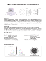
KSR98123 Sensor Mains Wiring box
Driver
Sensor Wiring Box
L (in)
1-10V -
1-10V +
N (in)
N (in)
1-10V -
1-10V +
L (in)
L (out)
L (out)
1-10V -
1-10V +
L (in)
N (in)
L (in)
1-10V -
1-10V +
L (out)
N (out)
From Mains Supply
Note
When Sensor is being used as on/off only ensure the
1-10v dimming pair (red and white) are terminated
seperately as to avoid control issues.
These fittings are Class II and do not require to be Earthed
Important Information
It is recommended that these controls are installed and fitted by a qualified electrician
ensuring the installation complies with current IEE wiring regulations & local building
control. These products are designed for connection to a 220-240V~50/60Hz supply.
Any faulty, broken or damaged sensors should be replaced immediately.
KSR will not accept responsibility for any claims arising from a poor installation.
Please Note: The limited warranty shall be deemed null and void in the following circumstances:
Failure by the installer, end user or any third party to exercise caution to protect any covered
product or part from outside damage, adverse temperature, humidity conditions, fluctuations in
the electrical system or physical abuse as well as failure related to workmanship in the installation
of the products or parts.

Installation Sheet KSR98123 Sensor Set Up Guide
Read these instructions before commencing installation. Please give these instructions to the owner/occupier after
installation to retain for future reference/maintainence.
Drg No. KSR98123-IS-C
KSR Lighting Ltd, Unit E Hazleton Interchange, Lakesmere Road, Horndean, Hampshire, PO8 9JU
KSR Lighting Aftersales: 023 92 674343
E-mail: aftersales@ksrlighting.com
24.01.2022RTG
Instructions
Please note mains must be isolated before sensor is opened and set, this is due to the
dipswitches being in close proximity of a high voltage circuit
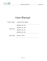
1. To access Dip Switches remove cap by releasing screw on top of Sensor casing (screw driver required)
2. With fixing screw removed twist cover anti-clockwise until the cover is free from the main body
3. referring to dipswitch table label on sensor housing and shown below set dip switches to desired setting and test
4. Once you are satisfied with your settings screw cover clockwise onto main sensor body and fix in place with screw to
secure.
Twist
Anti-clockwise
1 - Detection Range
Detection area can be reduced by selecting
the combination on the Dip Switches,
following the guide as shown here.
2 - Hold Time
Hold time means the time period you would
like the light to remain 'on' once the sensor
has detected movement.
3 - Standby Period
The standby period is the time the sensor
stays on for when the initial hold time has
lapsed, this is used when the user wants
the fitting to dim down to a reduced level
for a set period of time after the initial hold
time. If this is not required set dipswitches
to 0s and the sensor will turn off after the
hold time has lapsed
4 - Standby Dim Level
This is the level the sensor will dim down to
after the initial hold time has lapsed. This is
set in conjunction with switches 5,6 and 7.
5 - Daylight Sensor
The daylight sensor can be set to bring
the light 'on' at specific daylight levels.
To have the sensor function in daylight
set the Dip Switches to 2000lux.
Microwave sensors will detect movement through certain materials, if this
occurs reduce the detection area until any nuisance triggering stops.
Navara HB
Available finish: Black
IP65 Dimming Microwave Sensor
220-240V~50/60Hz
IP65
/