Page is loading ...

This product must be installed by a licensed electrician.
Instruction Manual
PIR Movement Sensors
Cat. No. 630S01WE, 630S01BL, 630SM01WE, 630SM01BL
1. Specifications
Cat. No. 630S01WE 630S01BL 630SM01WE 630SM01BL
Detection Method Passive Infrared (PIR)
Supply Voltage 230-240V a.c. 50Hz
Terminal Wiring Size 1 x 2.5mm2 to 2 x 1.5mm2
Standby Power < 1.0W
Detection / View Angle 180°
Detection Range / Distance 12m max (at ≤ 24°C)
Recommended Mounting Height 1.8m to 2.5m
Lux Adjustment Range 3 lux to 2000 lux
Time Adjustment Range (approx) 10 ± 3 sec to 15 ± 2 min
Switching Function Auto Mode only Auto Mode / Manual Override
IP Rating IP44
Weight 160g
Colour White Black White Black
Maximum Lighting Load 630S01WE 630S01BL 630SM01WE 630SM01BL
Incandescent 1200W
Fluorescent 400VA
Compact Fluorescent Lamp (CFL) 300VA
LED 300VA
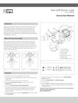
1.8-2.5m
12m
180˚
Max: 12m
(Fig. 1)

2. Sensor locations to be avoided
1. Near water features such as swimming pools or ponds. The movement and reflections are likely to create nuisance switching.
2. Near heat sources such as air conditioners, dryers, heaters or barbecues.
3. Locations which are subject to drastic changes in temperature.
4. Locations which are subject to bright light such as direct sunlight.
5. Locations frequented by animals such as pets or birds.
3. Where to mount your movement sensor
Before selecting a place to install your movement sensor, you should
note that movement across the scan area is more effective than
movement directly toward or away from the sensor (refer to Fig. 2). If
movement is made walking directly towards or away from the sensor and
not across, the apparent detection range will be substantially reduced.
Always mount the sensor in a sheltered position, i.e. under the eaves of
the house.
Ideally, the sensor should be mounted 1.8m to 2.5m above the area to be
scanned (refer to Fig. 1). Good Sensitivity Poor Sensitivity
4. Installation
Switch off power source before installation.
Ensure the power supply wiring comes from a circuit protected by a
suitable fuse or circuit breaker.
We recommend installing a wall switch for electrical isolation of the
sensor.
1. Remove the mounting bracket from the unit by loosening the screw on
the bottom (Fig. 3).
2. Use the mounting bracket as a template to mark the screw positions
onto the wall / ceiling. Ensure that the orientation of the mounting
bracket is such that the TIME & LUX controls are at the bottom of the
unit (Fig 4).
3. Insert the supply & load cables through the grommets on the
mounting bracket.
4. Install the mounting bracket onto the wall / ceiling.
5. Connect the supply & load cables to the terminal block as shown
in (Fig. 5). Ensure that the wires are secure and no bare wires are
exposed. This is a class II item, ensure this is maintained during
installation.
6. Install the unit back onto the mounting bracket and tighten the screw
on the bottom.
7. Adjust the sensor head to the desired position.
TIME & LUX controls
at the bottom
For wall mouting,
grommets to be
at the bottom
Forwallmoun+ng,grommets
tobeatthebo3om
TIME&LUXcontrols
atthebo3om
(RED)
LOAD
N L
IN~
(Neutral) (Active)
ON/OFF
switch
L' N L
(BLUE) (BROWN)
(Fig. 3)
(Fig. 2)
(Fig. 4)
(Fig. 5)

5. Setting the Controls
With the Sensor fully installed by an electrician and power on
1. Turn the TIME knob to minimum and turn the LUX knob to maximum
as shown in (Fig. 6).
2. Turn the wall switch on. The light/s should turn on immediately and
will remain on while the sensor warms up, for approximately
30 seconds. It will then turn off.
3. Walk through the coverage area and the light should turn on. This
confirms that the wiring is correct and that the light is operational.
4. Adjust the TIME knob to your desired setting.
5. To set the ambient light level at which the sensor will switch on, turn
the LUX knob to its fully anti-clockwise position. Wait for the desired
ambient light level, then turn the LUX knob clockwise while someone
walks through the coverage area. When the light switches on, release
the LUX knob.
(Fig. 6)
6. Time Adjustment
The TIME knob controls how long the light/s will stay on after movement is detected. Rotating the TIME knob clockwise increases the duration time. The
duration time varies between approximately 10 seconds (minimum) to approximately 15 minutes (maximum).
Note: Once the light has been triggered by the PIR sensor, any subsequent detection will start the timed period again from the beginning.
7. Lux Adjustment
The LUX knob controls the ambient light level at which the sensor will switch on. At the fully clockwise position, the sensor will operate 24 hours a day. At the
fully anti-clockwise position, the sensor will only operate at night. You can set the sensor to operate at the desired lux level by adjusting the LUX knob.
8. Manual Override (for 630SM01WE & 630SM01BL only)
1. When power is first switched on, the unit enters into the WARM UP
period for about 30 seconds, then automatically changes into
AUTO MODE.
2. During AUTO MODE, by switching the ON/OFF main switch off &
on twice in about 3 seconds, the unit will automatically change into
MANUAL MODE. In MANUAL MODE, the unit will remain ON and it
will not be affected by the TIME and LUX control levels. The unit will
remain in MANUAL MODE until the ambient light level reaches 100
lux (daylight), at which point it will change back to AUTO MODE.
3. During MANUAL MODE, by switching the ON/OFF main switch off
& on twice in about 3 seconds, the PIR detector will automatically
change into AUTO MODE.
4. During AUTO MODE or MANUAL MODE, by switching off the ON/OFF
main switch over 10 seconds and then on again, the PIR detector will
reset to WARM-UP period.
POWER ON AUTO MODE
MANUAL MODE
3 2
1
9. Maintenance / Cleaning
This product should only be cleaned with a damp cloth. Cleaning agents and solvents should not be used.

Warranty
HPM Legrand warrants this product for a period of 3 years from the
date of purchase.
These goods come with guarantees that cannot be excluded under
the Australian and New Zealand Consumer Laws. You are entitled to
a replacement or a refund for a major failure and for compensation
for any other reasonably foreseeable loss or damage. You are also
entitled to have the goods repaired if the goods fail to be acceptable
quality and the failure does not amount to a major failure.
See the Warranty card enclosed with this product for further details.
Customer Service
For all Customer Service and Technical Support
please call Monday to Friday during business hours.
HPM Legrand Australia
1300 369 777
www.hpm.com.au
HPM Legrand New Zealand
0800 476 009
www.hpm.co.nz
ABN: 31 000 102 661
LE09423AEA
10. Troubleshooting
PROBLEM POSSIBLE CAUSE POSSIBLE SOLUTION
Light does not switch on when there is
movement in the coverage area.
1. Power not available Check connections, switches and fuse.
2. Faulty light/globe. Replace light/globe.
3. Incorrect wiring. Recheck all wiring.
4. Controls set incorrectly. Change light adjustment (LUX knob).
5. Nearby lighting is too bright. Relocate the unit.
Light switches on for no apparent
reason.
(False triggering)
1. Heat sources (such as air conditioner, heater,
dryer or barbecue) are activating the sensor. Relocate the unit.
2. Animals (birds, pets etc) Possibly unavoidable.
3. Interference on the same circuit from on/off
switching of other electrical devices.
a. Check/Replace faulty switches.
b. Replace noisy fluoro tubes/starters.
c. Connect the unit to a different circuit.
4. Reflective objects (such as swimming pool) in the
coverage area. Relocate the unit.
Light does not switch off after set time
has elapsed.
1. Time is set for too long. Reduce time (TIME knob).
2. Wiring is incorrect. Recheck all wiring.
3. Unit damaged due to maximum load exceeded or
incompatible load type or failure of the load (such
as short circuit).
Identify and fix the cause of the failure.
Replace the unit with a new one.
4. Unit is in MANUAL MODE. Change to AUTO MODE.
Light switches on during daylight. 1. LUX knob is set to daylight position. Turn the LUX knob anti-clockwise to suit desired
light setting.
When setting the controls in daylight
the detection distance becomes shorter. 1. Interference by sunlight. Re-set controls at night.
9. Disclaimers
1. This product must be installed and used as per these instructions.
2. An IP rating of IP44 is generally considered suitable for external walls with supplementary protection such as overhanging eaves.
3. The IP rating of this product is only valid when installed on a flat and non-porous surface. Additional sealing may be required for irregular surfaces.
4. This product must be used with the loads specified only. Other load types should be used only when written confirmation is given by HPM Legrand.
5. This product contains no serviceable parts and no attempt should be made to repair this product. If the product is faulty it should be discarded.
6. This product is not suitable for installation in hazardous and/or corrosive areas.
7. Electrical installations periodically receive transient over voltages. This product has been designed to minimise the effect of such voltages on
connected equipment. It may not give full protection for extreme over-voltage transients such as those resulting from a close lighting strike.
8. This product utilises intellectual property in the form of registered designs, trademarks, and/or patents. Such intellectual property remains the
property of HPM Legrand in all cases.
9. This product has been designed to operate in ambient temperatures -10°C to 40°C.
10. Extended exposure to UV rays (such as exposure to direct sunlight) may cause discolouration of this product.
11. The material in this product may vary in colour from batch to batch. Colour matching from one batch to another cannot be guaranteed.
12. HPM Legrand reserves the right to modify the specification of this product at any time.
/