
Page 1
PM-11
Single Phase Power Analyser
Input Signal
PF
1Ø 2 Wire
5A/1Amp Selectable
45.0 to 65.0 Hz
0.100 - 1.000
UP to 9999A (Programm.)
INPUT
TECHNICAL SPECIFICATION
Set , Inc ,Dec
100 to 270V AC,50/60Hz
3VA
4 Digit , 3 Line 7 Seg.
0.56”Red LED
Display
Key
Power Supply
Burden
ACCURACY
DIMENSION
Size (mm)
Panel Cutout
96 (H) x 96 (W) x 54 (D) mm
92 (H) x 92 (W) mm
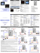
TERMINAL CONNECTION
DISPLAY, KEY & LED
CT Primary
AUXILIARY POWER SUPPLY
CT Secondary
Frequency
Class 0.5 (Standard)
ENVIRONMENTAL CONDITION
Working Temperature
Storage Temperature
Relative Humidity
0 to 55°C
0 to 55°C
95 % RH Non-
Condensing
IP-65 (Front side As per
IS/IEC 60529 : 2001)
Protection Level
( As per Request )
96 54
92
92
3
96
Outline Dimension (mm) Panel Cutout
Dimension (mm)
MECHANICAL INSTALLATION
KW
KVA
1. Prepare the panel cutout with proper dimensions as shown
above.
2. Fit the unit into the panel with the help of clamp given.
3. The equipment in its installed state must not come in close
proximity to any heating source, caustic vapors, oil steam,
or other unwanted process byproducts.
4. Use the specified size of crimp terminal (M3.5 screws) to
wire the terminal block. Tightening the screws on the
terminal block using the tightening torque of the range of
1.2 N.m.
5. Do not connect anything to unused terminals.
1. This equipment, being built-in-type, normally becomes a
part of main control panel and in such case the terminals
do not remain accessible to the end user after installation
and internal wiring.
INSTALLATION GUIDELINES
2. Do not allow pieces of metal, wire clippings, or fine metallic
fillings from installation to enter the product or else it may
lead to a safety hazard that may in turn endanger life or
cause electrical shock to the operator.
3. Circuit breaker or mains switch must be installed between
power source and supply terminal to facilitate power ‘ON’
or ‘OFF’ function. However this mains switch or circuit
breaker must be installed at convenient place normally
accessible to the operator.
4. Use and store the instrument within the specified ambient
temperature and humidity ranges as mentioned in this
manual.
MECHANICAL INSTALLATION
RESOLUTION
CT PRIMARY ENERGY RATE
PULSE OUTPUT
0.01 Kwh
5 to 75
0.1 Kwh
76 to 750
1 Kwh
751 to 7500
10 Kwh
7501 to 9999
1 2 3 4 78910
56
L N
Made in India
S1 S2
V2
V1
Range:
Voltage: 30V To 300V AC
Current:0.010A To 5 Amp
CT
www.multispanindia.com
System: 1Ph-2W
Primary CT Selectable: 5A To 9999A
Secondary CT Selectable:5A/1A
100
270V AC
~
50/60 Hz
3VA
+
PULSE
O/P
-
PM 11-A2-00

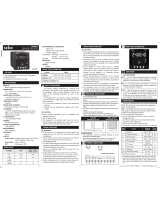
p a s S Enter Password 10
PARAMETER SETTING
1 0
Press key For 3 Second.
SET
Press + key
C T
5
p R I M
CT Primary
5A/9999Amp Selectable
C T
5
s e C
CT Secondary
5A/1Amp Selectable
p L S E
A U T O
M O D E
Pulse Mode
Auto / Manual
p L S E
0 0 1
O U T
Pulse Out
0.01, 0.1, 1 ,10
p L S E
1 0
t I m e
Pulse On Time
10ms to 500ms
If Auto
Press key to save & exit
SET
Press key
SET
Press key
SET
Press key
SET
p a s S Enter Password 15
1 5
Press key For 3 Second.
SET
Press + key
R S T
n O
Reset kwh
No/Yes
Press key
SET
Press key to save & exit
SET
Enter Password 15
Enter Password 10
1. The equipment should be cleaned regularly to avoid
blockage of ventilating parts.
2. Clean the equipment with a clean soft cloth. Do not use
isopropyl alcohol or any other cleaning agent.
3. Fusible resistor must not be replaced by operator.
Read complete instructions prior to installation
and operation of the unit.
WARNING : Risk of electric shock.
All safety related codifications, symbols and instructions
that appear in this operating manual or on the equipment must
be strictly followed to ensure the safety of the operating
personnel as well as the instrument.
If all the equipment is not handled in a manner specified
by the manufacturer, it might impair the protection provided
by the equipment.
WARNING : Risk of electric shock.
MAINTENANCE
SAFETY PRECAUTION
!
WARNING GUIDELINES
1. To prevent the risk of electric shock, power supply to the
equipment must be kept OFF while doing the wiring
arrangement. Do not touch the terminals while power is
being supplied.
2. To reduce electro magnetic interference, use wire with
adequate rating and twists of the same of equal size shall
be made with shortest connection.
3. Cable used for connection to power source, must have a
cross section of 1mm or greater. These wires should have
insulations capacity made of at least 1.5kV.
4. A better anti-noise effect can be expected by using
standard power supply cable for the instrument.
Reset Energy
Page 2
-
 1
1
-
 2
2


Ask a question and I''ll find the answer in the document
Finding information in a document is now easier with AI
Related papers
-
MULTISPAN AMP-23 Owner's manual
-
-
-
-
-
-
-
-
-
Other documents
-
 Masibus Multifunction Power & Energy Meter 2160-A User guide
-
 Masibus PM2160-A User manual
-
BLUE JAY BJ-195-3PS User manual
-
 Hoyt Electrical Instrument Works, Inc. Alpha 41A Plus Operating instructions
-
 Mikro RX380 User manual
-
 Rishabh Instruments RISH Master 3480 Operating instructions
-
 Selec EM306A Operating instructions
-
BLUE JAY BJ195-X Series User manual
-
Lumel RE11 Owner's manual


