Newport 710 Laser Diode User manual
- Category
- Laser levels
- Type
- User manual

Model 710
TO-CAN Laser Diode Mount
User’s Manual

ii Preface
Warranty
Newport Corporation warrants that this product will be free from defects in
material and workmanship and will comply with Newport’s published
specifications at the time of sale for a period of one year from date of
shipment. If found to be defective during the warranty period, the product
will either be repaired or replaced at Newport's option.
To exercise this warranty, write or call your local Newport office or
representative, or contact Newport headquarters in Irvine, California. You
will be given prompt assistance and return instructions. Send the product,
freight prepaid, to the indicated service facility. Repairs will be made and the
instrument returned freight prepaid. Repaired products are warranted for the
remainder of the original warranty period or 90 days, whichever first occurs.
Limitation of Warranty
The above warranties do not apply to products which have been repaired or
modified without Newport’s written approval, or products subjected to
unusual physical, thermal or electrical stress, improper installation, misuse,
abuse, accident or negligence in use, storage, transportation or handling. This
warranty also does not apply to fuses, batteries, or damage from battery
leakage.
THIS WARRANTY IS IN LIEU OF ALL OTHER WARRANTIES,
EXPRESSED OR IMPLIED, INCLUDING ANY IMPLIED WARRANTY
OF MERCHANTABILITY OR FITNESS FOR A PARTICULAR USE.
NEWPORT CORPORATION SHALL NOT BE LIABLE FOR ANY
INDIRECT, SPECIAL, OR CONSEQUENTIAL DAMAGES RESULTING
FROM THE PURCHASE OR USE OF ITS PRODUCTS.
First printing 2009
© 2009 by Newport Corporation, Irvine, CA. All rights reserved. No part of
this manual may be reproduced or copied without the prior written approval
of Newport Corporation.
This manual has been provided for information only and product
specifications are subject to change without notice. Any change will be
reflected in future printings.
Newport Corporation
1791 Deere Avenue
Irvine, CA, 92606
USA
Part No.
90029196
rev D

Preface iii
Confidentiality & Proprietary Rights
Reservation of Title:
The Newport programs and all materials furnished or produced in connection
with them ("Related Materials") contain trade secrets of Newport and are for
use only in the manner expressly permitted. Newport claims and reserves all
rights and benefits afforded under law in the Programs provided by Newport
Corporation.
Newport shall retain full ownership of Intellectual Property Rights in and to
all development, process, align or assembly technologies developed and other
derivative work that may be developed by Newport. Customer shall not
challenge, or cause any third party to challenge the rights of Newport.
Preservation of Secrecy and Confidentiality and Restrictions to Access:
Customer shall protect the Newport Programs and Related Materials as trade
secrets of Newport, and shall devote its best efforts to ensure that all its
personnel protect the Newport Programs as trade secrets of Newport
Corporation. Customer shall not at any time disclose Newport's trade secrets
to any other person, firm, organization, or employee that does not need
(consistent with Customer's right of use hereunder) to obtain access to the
Newport Programs and Related Materials. These restrictions shall not apply
to information (1) generally known to the public or obtainable from public
sources; (2) readily apparent from the keyboard operations, visual display, or
output reports of the Programs; 3) previously in the possession of Customer
or subsequently developed or acquired without reliance on the Newport
Programs; or (4) approved by Newport for release without restriction.
Trademarks
The Newport logo is a registered trademark of Newport Corporation in
Austria, Barbados, Benelux, Canada, the People’s Republic of China,
Denmark, France, Germany, Great Britain, Ireland, Japan, the Republic of
Korea, Spain, Sweden, and the United States.
Service Information
This section contains information regarding factory service for the source.
The user should not attempt any maintenance or service of the system or
optional equipment beyond the procedures outlined in this manual. Any
problem that cannot be resolved should be referred to Newport Corporation.

iv Preface
Technical Support Contacts
North America & Asia Europe
Newport Corporation Service Dept.
1791 Deere Ave. Irvine, CA 92606
Telephone: (949) 253-1694
Telephone: (800) 222-6440 x31694
Newport/MICRO-CONTROLE S.A.
Zone Industrielle
45340 Beaune la Rolande, FRANCE
Telephone: (33) 02 38 40 51 56
Asia
Newport Opto-Electronics
Technologies
253 Aidu Road, Bld #3, Flr 3, Sec C,
Shanghai 200131, China
Telephone: +86-21-5046 2300
Fax: +86-21-5046 2323
Newport Corporation Calling Procedure
If there are any defects in material or workmanship or a failure to meet
specifications, promptly notify Newport's Returns Department by calling 1-800-222-
6440 or by visiting our website at www.newport.com/returns within the warranty
period to obtain a Return Material Authorization Number (RMA#). Return the
product to Newport Corporation, freight prepaid, clearly marked with the RMA# and
we will either repair or replace it at our discretion. Newport is not responsible for
damage occurring in transit and is not obligated to accept products returned without
an RMA#.
E-mail: [email protected]
When calling Newport Corporation, please provide the customer care representative
with the following information:
•
••
•
Your Contact Information
•
••
•
Serial number or original order number
•
••
•
Description of problem (i.e., hardware or software)
To help our Technical Support Representatives diagnose your problem,
please note the following conditions:
•
••
•
Is the system used for manufacturing or research and development?
•
••
•
What was the state of the system right before the problem?
•
••
•
Have you seen this problem before? If so, how often?
•
••
•
Can the system continue to operate with this problem? Or is the system
non-operational?
•
••
•
Can you identify anything that was different before this problem
occurred?

Preface v
Table of Contents
Warranty................................................................................................. ii
Technical Support Contacts .................................................................. iv
Table of Contents ................................................................................... v
List of Figures ...................................................................................... vii
List of Tables........................................................................................ vii
1 Safety Precautions 1
1.1 Definitions and Symbols .............................................................. 1
1.1.1 General Warning or Caution .............................................1
1.1.2 Waste Electrical and Electronic Equipment (WEEE) .......1
1.2 Warnings and Cautions................................................................. 2
1.2.1 General Warnings..............................................................2
1.2.2 General Cautions ...............................................................2
1.2.3 Summary of Warnings and Cautions.................................4
2 General Information 5
2.1 Introduction .................................................................................. 5
2.2 Specifications ............................................................................... 5
3 Getting Started 7
3.1 Unpacking and Handling .............................................................. 7
3.2 Inspection for Damage ................................................................. 7
3.3 Parts List....................................................................................... 8
3.4 Choosing and Preparing a Suitable Work Surface ....................... 8
4 System Operation 9
4.1 Temperature Controlled Laser Diode Mount Anatomy ............... 9
4.2 Laser Diode Handling Precautions............................................. 10
4.3 Laser Diode Mounting................................................................ 11
4.3.1 Laser Diode Orientation ..................................................12
4.3.2 Wiring Diagram...............................................................12
4.3.3 Terminal Block Connections ...........................................14
4.3.4 Example...........................................................................16
4.4 Collimation Lens (Optional)....................................................... 17
4.5 Thermoelectric (TE) Modules .................................................... 17
4.6 Electrical Connections Overview ............................................... 17
4.6.1 Temperature Controller Connection................................18
4.6.2 Laser Diode Driver Connection.......................................18

vi Preface
4.7 Modulation Input Connection..................................................... 19
4.8 Purge Nipple............................................................................... 19
4.9 General Operating Procedures.................................................... 19
5 Disassembly Instructions 21
Disassembly instructions...................................................................... 21
6 Maintenance and Service 23
6.1 Obtaining Service ....................................................................... 23
6.2 Service Form .............................................................................. 24

Preface vii
List of Figures
Figure 1 General Warning or Caution Symbol............................................ 1
Figure 2 WEEE Directive Symbol................................................................. 1
Figure 3 Model 710 internal view .................................................................. 9
Figure 4 Model 710 rear view ..................................................................... 10
Figure 5 Three popular laser diode configurations ................................... 12
Figure 6 Cold plate socket connections....................................................... 13
Figure 7 Terminal block connections.......................................................... 15
Figure 8 Disassembly Diagram.................................................................... 22
List of Tables
Table 1 General Specifications..................................................................... 5
Table 2 Environmental Specifications......................................................... 6
Table 3 Terminal Block Connections ........................................................ 14

viii Preface
This page intentionally left blank

1 Safety Precautions
1.1 Definitions and Symbols
The following terms and symbols are used in this documentation where
safety-related issues occur.
1.1.1 General Warning or Caution
Figure 1 General Warning or Caution Symbol
The Exclamation Symbol in the figure above appears on the product and in
Warning and Caution tables throughout this document. This symbol
designates that documentation needs to be consulted to determine the nature
of a potential hazard, and any actions that have to be taken.
1.1.2 Waste Electrical and Electronic Equipment (WEEE)
Figure 2 WEEE Directive Symbol
This symbol on the product or on its packaging indicates that this product
must not be disposed of with regular waste. Instead, it is the user
responsibility to dispose of waste equipment according to the local laws. The
separate collection and recycling of the waste equipment at the time of
disposal will help to conserve natural resources and ensure that it is recycled
in a manner that protects human health and the environment. For information
about where the user can drop off the waste equipment for recycling, please
contact your local Newport Corporation representative. See Section 5 for
instructions on how to disassemble the equipment for recycling purposes.

2 Safety Precautions
1.2 Warnings and Cautions
The following are definitions of the Warnings, Cautions and Notes that are
used throughout this manual to call your attention to important information
regarding your safety, the safety and preservation of your equipment or an
important tip.
WARNING
Situation has the potential to cause bodily harm or death.
CAUTION
Situation has the potential to cause damage to property or
equipment.
NOTE
Additional information the user or operator should consider.
1.2.1 General Warnings
Observe these general warnings when operating or servicing this equipment:
•
••
•
Heed all warnings on the unit and in the operating instructions.
•
••
•
Do not use this equipment in or near water.
•
••
•
This equipment is grounded through the connections to the laser diode
driver and TE controller.
•
••
•
Route connecting cables so that they are not likely to be damaged.
•
••
•
Disconnect power before cleaning the equipment. Do not use liquid or
aerosol cleaners; use only a damp lint-free cloth.
1.2.2 General Cautions
Observe these cautions when operating this equipment:
•
••
•
If this equipment is used in a manner not specified in this manual, the
protection provided by this equipment may be impaired.
•
••
•
Follow precautions for static sensitive devices when handling this
equipment.
•
••
•
This product should only be powered as described in the manual.

Safety Precautions 3
•
••
•
There are no user-serviceable parts inside the Model 710 Laser Diode
Mount.
•
••
•
Adhere to good laser safety practices when using this equipment.

4 Safety Precautions
1.2.3 Summary of Warnings and Cautions
The following general warning and cautions are applicable to this instrument:
WARNING
Before operating the Models 710 Laser Diode Mount, please read
and understand all of Section 1.
WARNING
Do not attempt to operate this equipment if there is evidence of
shipping damage or you suspect the unit is damaged. Damaged
equipment may present additional hazards to you. Contact
Newport technical support for advice before attempting to plug
in and operate damaged equipment.
CAUTION
There are no user serviceable parts inside the Models 710
Temperature Controlled Laser Diode Mount. Work performed by
persons not authorized by Newport Corporation will void the
warranty. For instructions on obtaining warranty repair or
service, please refer to Section 6.

5
2 General Information
2.1 Introduction
The Model 710 Temperature Controlled Mount is a research quality unit that
provides precise temperature control of laser diodes. The mount includes
thermoelectric coolers and an efficient thermal design for optimum cooling or
heating. A dry nitrogen purge nipple allows the laser diode to be surrounded
in a nitrogen environment preventing condensation at below ambient
temperatures. Connectors on the back side of the Model 710 mount provide a
convenient manner to connect a Model 300B Series Temperature Controller
and a Model 500B Series Laser Diode Driver.
The Model 710 Temperature Controlled Mount has been designed to operate
laser diodes in TO-56 and TO-9 packaging, up to 2 Watts of power. Two 12.5
watt thermo-electric coolers actively cool and heat the laser diode. These
coolers are series connected and handle a maximum of 6.0 Amps at 7.5 volts
when operated at 25°C ambient temperature.
2.2 Specifications
Model 710
Types of Packages
accepted
TO-56 , TO-9, and pigtailed diodes
LD Current Input Range 0 to 3 Amps
Optical Beam Height 2.00 +- 0.02” (from bottom of unit without support)
TE Modules
Two 12.5 Watt, 20mm by 20mm series connected, 7.5V at 6 Amp
max at 25 Deg ambient temp
Connectors
15-pin male D-sub, laser temperature control 9-pin male D-sub,
laser diode current control, isolated chassis mount BNC and solder
post
Other Dry nitrogen purge nipple
Temperature Range -10°C to +80°C
Sensor Type 10 kΩ thermistor and AD592CN (user selectable)
Table 1 General Specifications

6 General Information
Size (H x W x D) [in. (mm)]
4.0 (101.6) x 4.0 (101.6) x 1.95 (49.53) without collimation
4.0 (101.6) x 4.0 (101.6) x 2.9 (7) with LP-05A-XYZ lens mount
Weight [lb (kg)] 1 (0.45)
Operating Temperature
0°C to 30°C
(<90% humidity non-condensing)
Storage Temperature
-30°C to + 60°C
(<90% humidity non-condensing)
Relative Humidity, Storage <90% humidity non-condensing
Use Location Indoor use only
Table 2 Environmental Specifications

7
3 Getting Started
3.1 Unpacking and Handling
The Temperature Controlled Laser Diode Mount is designed for easy setup
and use. To unpack, remove the Mount from its packaging. A post holder
system (not included) will be needed with this unit. The mount
accommodates 8-32 and M-4 threads (e.g. PS-2 post and PS-F clamping
fork).
3.2 Inspection for Damage
The LD Mount is carefully packaged at the factory to minimize the possibility
of damage during shipping. Inspect the box for external signs of damage or
mishandling. Inspect the contents of the box for damage. If there is visible
damage upon receipt, inform the shipping company and Newport Corporation
immediately. You may consider saving the box in case of shipping needs in
the future.
WARNING
Do not attempt to operate this equipment if there is evidence of
shipping damage or you suspect the unit is damaged. Damaged
equipment may present additional hazards to you. Contact
Newport technical support for advice before attempting to plug
in and operate damaged equipment.
CAUTION
The user is advised to save the packaging material in case the
unit has to be shipped to a different location. The packaging
material is specially designed to protect the unit during
shipping.

8 Getting Started
3.3 Parts List
The following is a list of parts included in Model 710:
User manual hardcopy part number 90029196
LD Mount
If parts are missing or there are questions regarding any of the above items,
please contact Newport Corporation technical support at 800-222-6440.
Customer supplied Equipment:
1. Adequate work surface (recommend Newport type breadboard
or optical table)
2. Post and post holder with 8-32 or M4 thread
3. DB-9 and DB-15 cables for LD control and Temperature
Controller (500-04 and 300-04 respectively)
4. LD Driver and Temp Controller (Newport models 500B and
300B series products recommended)
5. Anti-Static mat
6. Anti-static grounding wrist strap
7. Laser diode
8. Laser protective eyewear
3.4 Choosing and Preparing a Suitable Work Surface
The most important consideration while installing the laser diode into the
mount is protection against static discharge. Make sure you have the proper
static protection equipment including the following items:
1. Wrist strap and proper grounding connection
2. Static protective mat
3. Connect the LD mount to LD driver and Temp controller.
Make sure the units are grounded to the same ground as the
static wrist strap before installing the laser diode.
4. Contact Newport Technical support if you have further
questions.

4 System Operation
WARNING
Before operating the Models 710 Temperature Controlled Laser
Diode Mount, please read and understand all of Section 1.
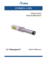
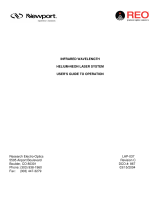
4.1 Temperature Controlled Laser Diode Mount Anatomy
The Laser diode mount has the following components:
Figure 3 Model 710 internal view
Retaining Plate
Cold Plate
Thermistor
AD592CN
Terminal
Blocks
Solder Post
BNC
Main PCBA
TO CAN
TE Coolers
Cold Plate
PCBA

10 Disassembly Instructions
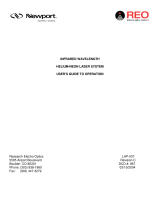
Figure 4 Model 710 rear view
4.2 Laser Diode Handling Precautions
CAUTION
Laser diodes are extremely sensitive to static discharge. The
manufacturer’s guidelines should be followed at all times when
handling laser diodes.
For a safe installation of the laser diode into the mount, please observe the
following:
a. All operators must be properly grounded before handling any laser
diode.
b. All related test and assembly equipment must be properly grounded.
Solder Post
BNC
DB-15
Connector
Temp Controller
DB-9
Connector
LD Driver
Nitrogen
Purge Nipple

Disassembly Instructions 11
Laser Diodes can only withstand a maximum reverse voltage of 2 to 3 volts
across their leads and no more than their maximum rated current in the
forward direction. Always follow the manufacturer’s instructions for
removing and handling laser diodes.
It is recommended that the connection to the laser diode remain floating
relative to Chassis Ground (earth ground). This prevents AC transients or
other voltage potentials due to multiple earth ground loops from damaging
the laser diode. Extreme care must be taken to ensure that all devices
including the Model 500B Series and any devices connected to the laser
diode, such as an external modulations source, are all grounded to the same
earth ground point. It is strongly recommended that this common earth
ground be the chassis ground (pin 3) on the sub-D 9-Pin connector. If you
have any questions on earth grounding a laser diode contact a Newport
Applications Engineer.
4.3 Laser Diode Mounting
The laser diode is mounted to the cold plate built into the Model 710
Temperature Controlled Mount. A combination 9mm/5.6mm retaining plate
holds the laser diode in place with two screws and accommodates both TO-
56 and TO-9 packages. The threaded holes in the cold plate used for the
retaining plate can also accommodate mounting the pigtailed laser diodes
supplied by Newport.
A 4 pin socket on a small PC board (Cold Plate PCBA) is provided in the
cold plate and each connection in the socket has a wire pigtail that will
connect to the terminal block. The wire connections can be changed to
accommodate various pin configurations. Also the polarization plane of the
diode may be changed by rotating the laser diode in 90 Degree increments in
the socket; the wiring connections will have to be changed accordingly.
Use the following steps to install and turn on a laser diode:
1. Determine desired orientation of the diode
2. Determine pin configuration of the diode
3. Connect the wires to the terminal block according the pin
configuration
4. Connect LD Mount to LD driver
5. Install Laser diode
6. Power up

12 Disassembly Instructions
4.3.1 Laser Diode Orientation
First step to mounting the laser diode is to determine the desired orientation
of beam output of the diode (e.g. polarization direction).
The emitting area of most laser diodes is rectangular in shape resulting in the
elliptical beam shape output. The polarization is generally aligned with the
shorter dimension of the rectangle (which is also the semi major axis of the
elliptical beam emitting from the diode).
The documentation provided with the laser diodes should describe or indicate
the orientation with respect to the markings on the TO-CAN.
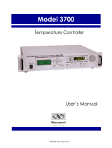
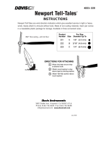
4.3.2 Wiring Diagram
Once the orientation of the TO-CAN is determined, the wiring can be
completed as follows:
1. Determine the pinout (see figure 5 for examples) from the spec sheet
of the laser diode
2. From the cold plate socket connections (see figure 6) the
corresponding wires can be connected to the proper terminal block.
3. For cases where there are common pins (3 pin LD configurations)
between photo diodes and laser diodes internal to the device, the
wiring can be made just as simply. See next section.
Figure 5 Three popular laser diode configurations
4. Make sure the wire connections are completed before inserting the
laser diode.
LD
PD
LD Cathode (-)
PD Anode(-)
LD Anode (+) / PD Cathode (+)
2
1
3
LD Cathode (-) / PD Anode(-)
LD Anode (+) PD Cathode (+)
LD
PD
1
2
3
LD Cathode (-) / PD Cathode(+)
LD Anode (+)
PD Anode(-)
LD PD
2
1
3
Page is loading ...
Page is loading ...
Page is loading ...
Page is loading ...
Page is loading ...
Page is loading ...
Page is loading ...
Page is loading ...
Page is loading ...
Page is loading ...
Page is loading ...
Page is loading ...
-
 1
1
-
 2
2
-
 3
3
-
 4
4
-
 5
5
-
 6
6
-
 7
7
-
 8
8
-
 9
9
-
 10
10
-
 11
11
-
 12
12
-
 13
13
-
 14
14
-
 15
15
-
 16
16
-
 17
17
-
 18
18
-
 19
19
-
 20
20
-
 21
21
-
 22
22
-
 23
23
-
 24
24
-
 25
25
-
 26
26
-
 27
27
-
 28
28
-
 29
29
-
 30
30
-
 31
31
-
 32
32


Newport 710 Laser Diode User manual
- Category
- Laser levels
- Type
- User manual
Ask a question and I''ll find the answer in the document
Finding information in a document is now easier with AI
Related papers
-
 Newport IRV1 Infrared Viewer Operating instructions
-
 Newport 1830-R Optical Meter User manual
-
 Newport 1936 & 2936-R Power Meter User manual
-
 Newport LPM Laser Diode Module User manual
-
 Newport 1936 & 2936-R Power Meter User manual
-
 Newport CONEX-LDS Autocollimator User manual
-
 Newport 3700 Temperature Controller User manual
-
 Newport LDC-3726 User manual
-
 Newport R-40137 Laser System User manual
-
 Newport R-33141 LHIP-0101-152 Laser System User manual


Other documents
-
Omega DP3520-PA Owner's manual
-
SRS LDC502 Owner's manual
-
 Davis Instruments Newport Tell-Tales Operating instructions
-
THORLABS LDM56F User manual
-
 THORLABS LDM56 User manual
-
 HOZAN H-767 Owner's manual
-
 OsTech Laser Lab Source TEC Series Operating instructions
-
omtech MYJG-50W User manual
-
omtech MYJG-80W User manual
-
Genius SP-HF1255A User manual


