Page is loading ...

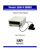
Single and Dual-Channel Optical Meters
User’s Manual
Model 1936-R/2936-R Series

2 Preface

3 Preface 3
EU Declaration of Conformity
We declare that the accompanying product, identified with the mark,
complies with the requirements of the Electromagnetic Compatibility
Directive, 2004/108/EC and the Low Voltage Directive 73/23/EEC.
Model Number: 1936-R, 2936-R
Year mark affixed: 2008
Type of Equipment: Electrical equipment for measurement, control and
laboratory use in industrial locations.
Manufacturer: Newport Corporation
1791 Deere Avenue
Irvine, CA 92606
Standards Applied:
Compliance was demonstrated to the following standards to the extent
applicable:
BS EN61326-1: 2006 “Electrical equipment for measurement, control and
laboratory use – EMC requirements”
This equipment meets the CISPR 11:2006+A2 Class A Group 1 radiated and
conducted emission limits.
BS EN 61010-1:2001, 2
nd
Edition “Safety requirements for electrical
equipment for measurement, control and laboratory use”
Bruno Rety Daniel Cabbell
Group Director of PPT Instrument and Motion Europe Director of Operational Excellence
Zone Industrielle 1791 Deere Avenue
45340 Beaune-la-Rolande, France Irvine, Ca. USA

4 Preface
Manual Updates
Dear Customer,
In an effort to keep the 1936/2936 Series Optical Meters
optimized for your applications, Newport will on occasion
update existing, and add new features to this instrument.
To utilize this new functionality will require an update to the
instrument's firmware, which can be easily accomplished by
the user, as described in this operator manual. As required,
Newport will also generate a new version of this user
manual, reflecting updates to the instrument.
Please check the Newport website (www.Newport.com)
for newer versions of the firmware and the operator manual,
which can be downloaded as a PDF file. Call your local
Newport application specialist if you need support with
locating or downloading these files.
Enjoy your new instrument!

5 Preface 5
Warranty
Newport Corporation warrants that this product will be free from defects in
material and workmanship and will comply with Newport’s published
specifications at the time of sale for a period of one year from date of
shipment. If found to be defective during the warranty period, the product
will either be repaired or replaced at Newport's option.
To exercise this warranty, write or call your local Newport office or
representative, or contact Newport headquarters in Irvine, California. You
will be given prompt assistance and return instructions. Send the product,
freight prepaid, to the indicated service facility. Repairs will be made and the
instrument returned freight prepaid. Repaired products are warranted for the
remainder of the original warranty period or 90 days, whichever first occurs.
Limitation of Warranty
The above warranties do not apply to products which have been repaired or
modified without Newport’s written approval, or products subjected to
unusual physical, thermal or electrical stress, improper installation, misuse,
abuse, accident or negligence in use, storage, transportation or handling. This
warranty also does not apply to fuses, batteries, or damage from battery
leakage.
THIS WARRANTY IS IN LIEU OF ALL OTHER WARRANTIES,
EXPRESSED OR IMPLIED, INCLUDING ANY IMPLIED WARRANTY
OF MERCHANTABILITY OR FITNESS FOR A PARTICULAR USE.
NEWPORT CORPORATION SHALL NOT BE LIABLE FOR ANY
INDIRECT, SPECIAL, OR CONSEQUENTIAL DAMAGES RESULTING
FROM THE PURCHASE OR USE OF ITS PRODUCTS.
First printing 2008
© 2008 by Newport Corporation, Irvine, CA. All rights reserved. No part of
this manual may be reproduced or copied without the prior written approval
of Newport Corporation.
This manual has been provided for information only and product
specifications are subject to change without notice. Any change will be
reflected in future printings.
Newport Corporation
1791 Deere Avenue
Irvine, CA, 92606
USA
Part No. 90039770 rev B

6 Preface
Confidentiality & Proprietary Rights
Reservation of Title:
The Newport programs and all materials furnished or produced in connection
with them ("Related Materials") contain trade secrets of Newport and are for
use only in the manner expressly permitted. Newport claims and reserves all
rights and benefits afforded under law in the Programs provided by Newport
Corporation.
Newport shall retain full ownership of Intellectual Property Rights in and to
all development, process, align or assembly technologies developed and other
derivative work that may be developed by Newport. Customer shall not
challenge, or cause any third party to challenge the rights of Newport.
Preservation of Secrecy and Confidentiality and Restrictions to Access:
Customer shall protect the Newport Programs and Related Materials as trade
secrets of Newport, and shall devote its best efforts to ensure that all its
personnel protect the Newport Programs as trade secrets of Newport
Corporation. Customer shall not at any time disclose Newport's trade secrets
to any other person, firm, organization, or employee that does not need
(consistent with Customer's right of use hereunder) to obtain access to the
Newport Programs and Related Materials. These restrictions shall not apply
to information (1) generally known to the public or obtainable from public
sources; (2) readily apparent from the keyboard operations, visual display, or
output reports of the Programs; 3) previously in the possession of Customer
or subsequently developed or acquired without reliance on the Newport
Programs; or (4) approved by Newport for release without restriction.
Service Information
This section contains information regarding factory service for the source.
The user should not attempt any maintenance or service of the system or
optional equipment beyond the procedures outlined in this manual. Any
problem that cannot be resolved should be referred to Newport Corporation.
Copyright and Trademark Information
WINDOWS
TM
is a registered Trademark of Microsoft Corporation
LabVIEW is a registered Trademark of National Instruments INC.
Visual Basic is a registered Trademark of Microsoft Corporation.
Visual C++ is a registered Trademark of Microsoft Corporation.

7 Preface 7
Technical Support Contacts
North America & Asia
Europe
Newport Corporation Service Dept.
1791 Deere Ave. Irvine, CA 92606
Telephone: (949) 253-1694
Telephone: (800) 222-6440 x31694
Newport/MICRO-CONTROLE S.A.
Zone Industrielle
45340 Beaune la Rolande, FRANCE
Telephone: (33) 02 38 40 51 56
Asia
Newport Opto-Electronics
Technologies (Wuxi) Co.
No. 36, 38 Xikun Road, WSIP, Wuxi,
Jiangsu, 214028 China
Telephone: +86-510-8018-3000
Fax: +86-510-8018-3289
Newport Corporation Calling Procedure
If there are any defects in material or workmanship or a failure to meet
specifications, promptly notify Newport's Returns Department by calling 1-800-222-
6440 or by visiting our website at www.newport.com/returns within the warranty
period to obtain a Return Material Authorization Number (RMA#). Return the
product to Newport Corporation, freight prepaid, clearly marked with the RMA# and
we will either repair or replace it at our discretion. Newport is not responsible for
damage occurring in transit and is not obligated to accept products returned without
an RMA#.
E-mail: rma.service@newport.com
When calling Newport Corporation, please provide the customer care representative
with the following information:
Your Contact Information
Serial number or original order number
Description of problem (i.e., hardware or software)
To help our Technical Support Representatives diagnose your problem, please note
the following conditions:
Is the system used for manufacturing or research and development?
What was the state of the system right before the problem?
Have you seen this problem before? If so, how often?
Can the system continue to operate with this problem? Or is the system non-
operational?
Can you identify anything that was different before this problem occurred?

8 Preface
IMPORTANT NOTE
Before plugging the instrument into a PC via a USB communication port, please
make sure that the USB Drivers are installed. Run Setup.exe from the Software CD
that came with your product. The installation program will configure the PC with the
1936/2936 Series USB drivers.

9 Preface 9
Table of Contents
EU Declaration of Conformity ............................................................... 3
Warranty ................................................................................................. 5
Technical Support Contacts ................................................................... 7
Table of Contents ................................................................................... 9
List of Figures ...................................................................................... 16
List of Tables........................................................................................ 17
1 Safety Precautions 19
1.1 Definitions and Symbols ............................................................ 19
1.1.1 General Warning or Caution ...........................................19
1.1.2 Electric Shock ..................................................................19
1.1.3 Protective Conductor Terminal .......................................19
1.1.4 European Union CE Mark ...............................................20
1.1.5 Alternating voltage symbol .............................................20
1.1.6 On ....................................................................................20
1.1.7 Off ....................................................................................20
1.1.8 Fuses ................................................................................21
1.1.9 Frame or Chassis .............................................................21
1.1.10 USB Connector Symbol ..................................................21
1.1.11 Waste Electrical and Electronic Equipment (WEEE) .....21
1.1.12 Control of Hazardous Substances ....................................22
1.2 Warnings and Cautions ............................................................... 22
1.2.1 General Warnings ............................................................22
1.2.2 General Cautions .............................................................24
1.3 Location of Warnings ................................................................. 25
1.3.1 Rear Panel ........................................................................25
2 General Information 26
2.1 Introduction ................................................................................ 26
2.2 Optical Meter Functionality ....................................................... 27
2.3 Model 1936-R ............................................................................. 27
2.4 Model 2936-R ............................................................................. 27
2.5 Calibration .................................................................................. 27
2.6 Specifications ............................................................................. 27
2.6.1 Physical Specifications: ...................................................27
2.6.2 Electrical Specifications ..................................................28
2.7 Unpacking and Handling ............................................................ 30
2.8 Inspection for Damage ............................................................... 30
2.9 Available Options and Accessories ............................................ 31
2.10 Parts List ..................................................................................... 31
2.11 Choosing and Preparing a Suitable Work Surface ..................... 31
2.12 Electrical Requirements .............................................................. 31
2.13 Power Supplies ........................................................................... 32
3 System Overview 34

10 Preface
3.1 Startup Procedure ....................................................................... 34
3.2 Front Panel Layout ..................................................................... 34
3.2.1 Front Panel Elements .......................................................35
3.2.2 Understanding the Main Screen ......................................35
3.3 Rear Panel Layout ...................................................................... 35
3.3.1 Elements That Vary by Model (on back panel) ...............35
3.3.2 Panel Layout ....................................................................36
3.3.3 Changing Voltage Settings ..............................................38
3.4 Rack Mounting the 1936/2936 Series ........................................ 39
4 System Operation 42
4.1 Front Panel Keys ........................................................................ 42
4.1.1 Power Switch ...................................................................42
4.1.2 Setup/Enter Key ...............................................................43
4.1.3 Esc Key ............................................................................44
4.1.4 Navigation and Selection Keys .......................................44
4.1.4.1 Channel Swapping ................................................ 44
4.1.4.2 Navigation ............................................................. 45
4.1.5 Soft Keys .........................................................................45
4.1.6 Dedicated Keys ................................................................45
4.1.6.1 Range .................................................................... 46
4.1.6.2 Mode ..................................................................... 47
4.1.6.3 Hold....................................................................... 47
4.1.6.4 Filter ...................................................................... 47
4.1.6.5 Lambda (λ) Key .................................................... 48
4.1.6.6 Set Zero Offset (Zero Key) ................................... 49
4.2 Measurement Settings ................................................................ 49
4.2.1 Changing the Measurement Settings ...............................49
4.2.1.1 Wavelength Selection ........................................... 49
4.2.1.2 Range Selection and Range Type (Rng. type) ...... 49
4.2.1.3 Attenuator On/Off ................................................. 50
4.2.1.4 Analog and Digital Filter Selection ...................... 50
4.2.1.5 Units Selection ...................................................... 50
4.2.1.6 Mode Selection ..................................................... 51
4.2.1.7 Spot Size ............................................................... 51
4.2.1.8 Number of Digits Setting ...................................... 51
4.2.1.9 Offset Field ........................................................... 51
4.2.2 Detector Information .......................................................51
4.3 Trigger Setup .............................................................................. 52
4.3.1 Trigger Delay ...................................................................52
4.3.2 Trigger Start .....................................................................52
4.3.3 Trigger Stop .....................................................................53
4.4 Wavelength Setting .................................................................... 53
4.5 Display Color .............................................................................. 54

11 Preface 11
4.6 USB Address and RS232 Parameters ......................................... 55
4.7 Statistics ...................................................................................... 55
4.7.1 Graph ...............................................................................56
4.8 Math Functions ........................................................................... 57
4.9 Measurement Correction Settings .............................................. 58
4.10 59
4.11 Display Modes ............................................................................ 59
4.11.1 Numeric Display ..............................................................59
4.11.2 Analog Bar .......................................................................59
4.11.3 Analog Needle .................................................................61
4.11.4 Vertical Chart ..................................................................61
4.12 Firmware Upgrade Procedure ..................................................... 62
5 Performing Basic Measurements 64
5.1 Introduction ................................................................................ 64
5.2 Measurement Modes and Units .................................................. 64
5.3 CW Measurements ( with 918D or 818P Detectors ) ................. 65
5.4 Peak-to-Peak Power Measurements (918D Detectors) .............. 66
5.5 Power Ratio and Power Reference Measurements ..................... 66
5.6 Pulse Energy Measurements (818E Detectors) .......................... 67
5.7 Signal Integration Measurements (918D or 818P Detectors) ..... 68
5.8 Measuring Laser Pulse Energy with an 818P Thermopile
Detector (Single Shot) .............................................................. 68
5.9 Frequency Measurements (918D or 818E Detectors) ................ 70
5.10 RMS Measurements ................................................................... 71
6 Software Application 72
6.1 Overview .................................................................................... 72
6.2 Connection .................................................................................. 72
6.3 General Usage ............................................................................ 73
6.4 Menu Structure ........................................................................... 73
7 Computer Interfacing 75
7.1 General Guidelines ..................................................................... 75
7.2 Computer Interface Terminology ............................................... 75
7.2.1 <…> Delimiting Punctuation ..........................................75
7.2.2 <CR> Carriage Return .....................................................75
7.2.3 <LF> Line Feed ...............................................................75
7.2.4 (;) Semicolons ..................................................................75
7.2.5 <number> Numerical Types ............................................76
7.2.6 <string> String Types ......................................................76
7.2.7 Command Termination ....................................................76
7.2.8 Response Termination .....................................................76
7.3 RS-232C Communication .......................................................... 76
7.3.1 Setting Echo Mode From the Keypad .............................77
7.3.2 Setting Echo Mode via Remote Interface ........................77
7.3.3 Setting the USB Address .................................................77

12 Preface
7.4 USB Communication .................................................................. 77
8 Communication Command Reference 79
8.1 Model 1936/2936 Series Remote Interface Commands ............. 79
8.2 Command Overview ................................................................... 79
8.2.1 Activate a Specific Channel ............................................80
8.3 Command Description ................................................................ 80
8.3.1 Command Glossary .........................................................80
8.3.2 Display Commands .........................................................82
8.3.2.1 DISP:BRIGHT ...................................................... 82
8.3.2.2 DISP:BRIGHT? .................................................... 83
8.3.3 Power Meter Commands .................................................83
8.3.3.1 *IDN? .................................................................... 83
8.3.3.2 *RCL ..................................................................... 83
8.3.3.3 *SAV..................................................................... 84
8.3.3.4 ADDRess .............................................................. 84
8.3.3.5 ADDRess?............................................................. 85
8.3.3.6 BEEP ..................................................................... 85
8.3.3.7 BEEP? ................................................................... 85
8.3.3.8 ECHO .................................................................... 85
8.3.3.9 ECHO? .................................................................. 86
8.3.3.10 ERRors? ................................................................ 86
8.3.3.11 ERRSTR? .............................................................. 86
8.3.3.12 PM:ANALOGFILTER ......................................... 87
8.3.3.13 PM: ANALOGFILTER? ...................................... 87
8.3.3.14 PM:ANALOG:IMP............................................... 87
8.3.3.15 PM:ANALOG:IMP? ............................................. 88
8.3.3.16 PM:ANALOG:OUT ............................................. 88
8.3.3.17 PM:ANALOG:OUT? ............................................ 88
8.3.3.18 PM:ATT ................................................................ 89
8.3.3.19 PM:ATT? .............................................................. 89
8.3.3.20 PM:ATTSN? ......................................................... 89
8.3.3.21 PM:AUTO............................................................. 89
8.3.3.22 PM:AUTO? ........................................................... 90
8.3.3.23 PM:CALDATE? ................................................... 90
8.3.3.24 PM:CALTEMP? ................................................... 90
8.3.3.25 PM:CHANnel ....................................................... 91
8.3.3.26 PM:CHANnel? ...................................................... 91
8.3.3.27 PM:CORR ............................................................. 91
8.3.3.28 PM:CORR? ........................................................... 92
8.3.3.29 PM:DETMODEL? ................................................ 92

13 Preface 13
8.3.3.30 PM:DETSIZE? ...................................................... 92
8.3.3.31 PM:DETSN? ......................................................... 92
8.3.3.32 PM:DIGITALFILTER .......................................... 93
8.3.3.33 PM:DIGITALFILTER? ........................................ 93
8.3.3.34 PM:DPower? ......................................................... 93
8.3.3.35 PM:DS:BUFfer ..................................................... 94
8.3.3.36 PM:DS:BUFfer? ................................................... 94
8.3.3.37 PM:DS:CLear ....................................................... 94
8.3.3.38 PM:DS: Count? ..................................................... 94
8.3.3.39 PM:DS:ENable ..................................................... 95
8.3.3.40 PM:DS:ENable? .................................................... 95
8.3.3.41 PM:DS:GET? ........................................................ 95
8.3.3.42 PM:DS:INTerval ................................................... 96
8.3.3.43 PM:DS:INTerval? ................................................. 96
8.3.3.44 PM:DS:SAVEBUFFER ........................................ 96
8.3.3.45 PM:DS:SIZE ......................................................... 97
8.3.3.46 PM:DS:SIZE? ....................................................... 97
8.3.3.47 PM:DS:UNITs?..................................................... 97
8.3.3.48 PM:FILTer ............................................................ 98
8.3.3.49 PM:FILTer? .......................................................... 98
8.3.3.50 PM:FREQuency? .................................................. 98
8.3.3.51 PM:Lambda........................................................... 99
8.3.3.52 PM:Lambda? ......................................................... 99
8.3.3.53 PM:MAX:Lambda? .............................................. 99
8.3.3.54 PM:MAX:Power? ............................................... 100
8.3.3.55 PM:MIN:Lambda? .............................................. 100
8.3.3.56 PM:MIN:Power? ................................................. 100
8.3.3.57 PM:MEAS:TIMEOUT ....................................... 100
8.3.3.58 PM:MEAS:TIMEOUT? ...................................... 101
8.3.3.59 PM:MODE .......................................................... 101
8.3.3.60 PM:MODE? ........................................................ 102
8.3.3.61 PM:Power? .......................................................... 102
8.3.3.62 PM:PWS? ............................................................ 102
8.3.3.63 PM:RANge ......................................................... 103
8.3.3.64 PM:RANge? ........................................................ 103
8.3.3.65 PM:REF:VALue ................................................. 103
8.3.3.66 PM:REF:VALue? ............................................... 104
8.3.3.67 PM:REF:STOre................................................... 104
8.3.3.68 PM:RESPonsivity? ............................................. 104

14 Preface
8.3.3.69 PM:RUN ............................................................. 105
8.3.3.70 PM:RUN? ........................................................... 105
8.3.3.71 PM:SATLEVEL ................................................. 105
8.3.3.72 PM:SATLEVEL? ................................................ 105
8.3.3.73 PM:SPOTSIZE ................................................... 106
8.3.3.74 PM:SPOTSIZE? .................................................. 106
8.3.3.75 PM:STAT:MAX? ............................................... 106
8.3.3.76 PM:STAT:MEAN? ............................................. 107
8.3.3.77 PM:STAT:MIN? ................................................. 107
8.3.3.78 PM:STAT:MAXMIN? ........................................ 107
8.3.3.79 PM:STAT:SDEViation? ..................................... 107
8.3.3.80 PM:Temp?........................................................... 108
8.3.3.81 PM:Temppoll ...................................................... 108
8.3.3.82 PM:Temppoll? .................................................... 108
8.3.3.83 PM:THERM:PREDICT ...................................... 108
8.3.3.84 PM:THERM:PREDICT? .................................... 109
8.3.3.85 PM:TRIG:EXTernal ........................................... 109
8.3.3.86 PM:TRIG:EXTernal? .......................................... 109
8.3.3.87 PM:TRIG:EDGE................................................. 110
8.3.3.88 PM:TRIG:EDGE? ............................................... 110
8.3.3.89 PM:TRIG:HOLDoff ........................................... 110
8.3.3.90 PM:TRIG:HOLDoff? .......................................... 111
8.3.3.91 PM:TRIG:START............................................... 111
8.3.3.92 PM:TRIG:START? ............................................. 111
8.3.3.93 PM:TRIG:STOP ................................................. 112
8.3.3.94 PM:TRIG:STOP? ................................................ 112
8.3.3.95 PM:TRIG:STATE ............................................... 112
8.3.3.96 PM:TRIG:STATE? ............................................. 113
8.3.3.97 PM:TRIG:VALUE .............................................. 113
8.3.3.98 PM:TRIG:VALUE? ............................................ 113
8.3.3.99 PM:TRIG:TIME ................................................. 114
8.3.3.100 PM:TRIG:TIME? ............................................. 114
8.3.3.101 PM:UNITs........................................................ 114
8.3.3.102 PM:UNITs? ...................................................... 115
8.3.3.103 PM:ZEROSTOre.............................................. 115
8.3.3.104 PM:ZEROVALue ............................................ 115
8.3.3.105 PM:ZEROVALue? .......................................... 115
9 Principles of Operation 117

15 Preface 15
9.1 Introduction .............................................................................. 117
9.2 Analog Signal Flow .................................................................. 117
9.3 Digitized Signal Flow ............................................................... 118
9.4 Typical Detector Signals .......................................................... 119
9.5 Thermopile Detector Signals .................................................... 120
9.6 Pulse Energy Detector Signals ................................................. 120
9.7 Peak-to-Peak (Photodiode) Detector Signals ........................... 121
9.8 Integration of Detector Signals ................................................. 122
9.9 Analog Output .......................................................................... 123
9.10 Measurement Considerations ................................................... 124
9.10.1 Detector Calibration and Accuracy ...............................124
9.10.2 Quantum Detector Temperature Effects ........................124
9.10.3 Thermopile Detector Temperature Effects ....................125
9.10.4 Energy Detector Temperature Effects ...........................126
9.10.5 Ambient and Stray Light ...............................................126
9.10.6 Signal Filtering ..............................................................127
9.11 Common Measurement Errors ................................................. 128
10 Maintenance and Service 130
10.1 Enclosure Cleaning ................................................................... 130
10.2 Fuse Replacement ..................................................................... 130
10.3 Obtaining Service ..................................................................... 131
10.4 Service Form ............................................................................ 132
11 Appendix A – Syntax and Definitions 134
11.1 Definition of <string> ............................................................... 134
11.2 Definition of <number> ............................................................ 135
12 Appendix B – Error Messages 138
12.1 Introduction .............................................................................. 138
12.2 Command Errors ...................................................................... 138
12.3 Execution Errors ....................................................................... 139
12.4 Device Errors ............................................................................ 140
13 Appendix C - Legacy Commands Reference 142
14 Appendix D – Sample Programs 144
14.1 Programming Samples .............................................................. 144
14.2 LabVIEW ................................................................................. 144
14.3 Microsoft® Visual Basic .......................................................... 144
14.4 Microsoft Visual C++ ............................................................... 144
14.5 Microsoft .NET ......................................................................... 144
15 Appendix E – Disassembly Instructions 146
15.1 Disassembly instructions .......................................................... 146

16 Preface
List of Figures
Figure 1 General Warning or Caution Symbol ............................................. 19
Figure 2 Electrical Shock Symbol ................................................................ 19
Figure 3 Protective Conductor Terminal Symbol ........................................ 19
Figure 4 CE Mark ......................................................................................... 20
Figure 5 Alternating Voltage Symbol .......................................................... 20
Figure 6 On Symbol ..................................................................................... 20
Figure 7 Off Symbol ..................................................................................... 20
Figure 8 Fuse Symbol ................................................................................... 21
Figure 9 Frame or Chassis Terminal Symbol ............................................... 21
Figure 10 USB connector Symbol .................................................................. 21
Figure 11 WEEE Directive Symbol ............................................................... 21
Figure 12 RoHS Compliant Symbol ............................................................... 22
Figure 13 AC Receptacle Warning Label....................................................... 24
Figure 14 Locations of warnings on the rear panel ........................................ 25
Figure 15 Front Panel Layout ......................................................................... 34
Figure 16 1936-R Rear Panel Layout ............................................................. 36
Figure 17 2936-R Rear Panel Layout ............................................................. 37
Figure 18 PM1 –RACK mounting kit ............................................................ 39
Figure 19 PM2 –RACK mounting kit ............................................................ 40
Figure 20 Mounting details for the PM1 –RACK mounting kit .................... 41
Figure 21 Front Panel keys ............................................................................. 42
Figure 22 Power Switch ................................................................................. 42
Figure 23 Navigation/Selection and Setup/Enter keys ................................... 43
Figure 24 Main screen .................................................................................... 43
Figure 25 Measurement Settings screen ......................................................... 44
Figure 26 Channel A primary ......................................................................... 44
Figure 27 Channel B primary ......................................................................... 44
Figure 28 Soft keys ......................................................................................... 45
Figure 29 Dedicated keys ............................................................................... 45
Figure 30 Manual Range mode ...................................................................... 46
Figure 31 Auto Range mode ........................................................................... 46
Figure 32 This screen is displayed after pressing the Config soft key ........... 46
Figure 33 Mode selection screen .................................................................... 47
Figure 34 Measurement is on hold ................................................................. 47
Figure 35 Filter selection screen ..................................................................... 47
Figure 36 Filter configuration screen ............................................................. 48
Figure 37 Digital Filter editing ....................................................................... 48
Figure 38 Wavelengths screen ........................................................................ 48
Figure 39 Zero Selection ................................................................................ 49
Figure 40 Measurement Settings screen ......................................................... 49
Figure 41 Accessing the Trigger Setup screen ............................................... 52
Figure 42 Trigger Delay waveforms .............................................................. 52
Figure 43 Predefined color schemes ............................................................... 54

17 Preface 17
Figure 44 Setup screen ................................................................................... 54
Figure 45 System Settings screen ................................................................... 54
Figure 46 About screen................................................................................... 55
Figure 47 Statistics screen .............................................................................. 55
Figure 48 Graph screen................................................................................... 56
Figure 49 Math field ....................................................................................... 57
Figure 50 Math configuration screen.............................................................. 57
Figure 51 Measurement Settings .................................................................... 58
Figure 52 Correction Settings ......................................................................... 58
Figure 53 Mode selection screen .................................................................... 59
Figure 54 The Numeric display ...................................................................... 59
Figure 55 Analog Bar ..................................................................................... 59
Figure 56 Auto Zoom ..................................................................................... 60
Figure 57 Analog Needle display ................................................................... 61
Figure 58 Vertical chart with 3 measurements per line .................................. 61
Figure 59 Vertical chart with 1 measurement per line ................................... 61
Figure 60 Measuring Laser Pulse Energy via a Thermopile in CW Integrate
Mode .............................................................................................. 69
Figure 61 Application front panel .................................................................. 72
Figure 62 Application Advanced Options (Configuration Tab) ..................... 73
Figure 63 RS-232 9 Pin to 9-Pin Cable Connections. Cable terminators (RS-
232) ................................................................................................ 77
Figure 64 Model 1936/2936 Series Analog Signal Flow Diagram .............. 117
Figure 65 Thermopile Signals exhibit 1 to 10 second time constants. ......... 120
Figure 66 Typical Newport Energy Detector Signal Waveform .................. 121
Figure 67 Negative Baseline Voltage. .......................................................... 121
Figure 68 Time Varying Signal Measurements. ........................................... 122
Figure 69 Integrated Energy Via a Trapezoid Approximation. .................... 122
Figure 70 Measuring Laser Pulse Energy with a Thermopile. ..................... 123
Figure 71 Fuse Replacement ........................................................................ 130
Figure 72 Disassembled 1936/2936 model .................................................. 147
List of Tables
Table 1 Available Measurement Modes and Valid Units. .......................... 65
Table 2 Root level Commands/Queries Summary ...................................... 80
Table 3 Tree Level Commands/Queries Summary ..................................... 82
Table 4 Analog Signal Flow Paths. ........................................................... 118
Table 5 Analog Output Range Table......................................................... 123
Table 6 Common Measurement Errors ..................................................... 128
Table 7 Legacy Commands Reference...................................................... 143

18 Preface
This page is intentionally left blank

1 Safety Precautions
1.1 Definitions and Symbols
The following terms and symbols are used in this documentation and also
appear on the Models 1936/2936 Series Optical Power Meters where safety-
related issues occur.
1.1.1 General Warning or Caution
Figure 1 General Warning or Caution Symbol
The Exclamation Symbol in the figure above appears in Warning and Caution
tables throughout this document. This symbol designates an area where
personal injury or damage to the equipment is possible.
1.1.2 Electric Shock
Figure 2 Electrical Shock Symbol
The Electrical Shock Symbol in the figure above appears throughout this
manual. This symbol indicates a hazard arising from dangerous voltage.
Any mishandling could result in irreparable damage to the equipment, and
personal injury or death.
1.1.3 Protective Conductor Terminal
Figure 3 Protective Conductor Terminal Symbol
The protective conductor terminal symbol in the above figure identifies the
location of the bonding terminal, which is bonded to conductive accessible
parts of the enclosure for safety purposes.

20 Safety Precautions
1.1.4 European Union CE Mark
Figure 4 CE Mark
The presence of the CE Mark on Newport Corporation equipment means that
it has been designed, tested and certified as complying with all applicable
European Union (CE) regulations and recommendations.
1.1.5 Alternating voltage symbol
Figure 5 Alternating Voltage Symbol
This international symbol implies an alternating voltage or current.
1.1.6 On
Figure 6 On Symbol
The On Symbol in the figure above represents a power switch position on the
1936/2936 Series Optical Power Meters. This symbol represents a Power On
condition.
1.1.7 Off
Figure 7 Off Symbol
The Off Symbol in the figure above represents a power switch position on the
1936/2936 Series Optical Power Meters. This symbol represents a Power Off
condition.
~
/
