Page is loading ...

12
Contents
Section Page
Kit contents 13
Specification 13
RC functions 13
Receiving system components 13
Notes on using epoxy 14
Fuselage 14
Removing the fuselage nose 14
Trimming the motor bulkhead 14
Cooling air slots 14
Installing the battery holder 14
Towhook support block 15
Completing the canopy 15
Wing joiners 15
Wing retainers 15
Wing / fuselage fit 15
Trimming the canopy 15
Fuselage slot for rudder bowden cable 15
Completing the tailplane 15
Attaching the fin to the fuselage 15
Installing the “EinStein” module 15
Installing conventional RC components 16
Installing the receiver battery 16
Completing the fuselage linkages 16
Final work on the fuselage 16
Completing the wings 16
Installing the wing-mounted servos 16
Separating the ailerons and landing flaps 16
Aileron linkages 17
Electrical connections, wing / fuselage 17
Centre of Gravity and longitudinal dihedral 17
Control surface travels 17
Preparing for the first flight 17
Test flying 17
Range testing 18
The first flight 18
Safety 18
The fascination of it all 18
Appendix 19
Surface finishing 19
Applying the decals 19
Parts list 20

13
BUILDING INSTRUCTIONS
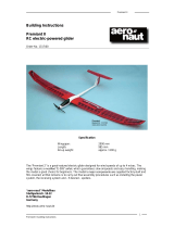
alpha junior Uncovered Order No. 21 4021
alpha junior Factory-covered Order No. 21 4132
alpha club Uncovered Order No. 21 4022
alpha club Factory-covered Order No. 21 4130
High-performance model glider / electric glider designed for
the beginner.
Dear fellow modeller,
Congratulations on your choice of the alpha junior / club
high-performance glider for the beginner. These are attractive
model aircraft with docile handling, and we hope you will
thoroughly enjoy building and flying your model.
MULTIPLEX model kits are subject to constant quality checks
throughout the production process, and we sincerely hope
that you are happy with the contents of your kit. However, we
would ask you to check all the parts before you start
construction, as we cannot exchange components which
you have already worked on. If you find any part is not
acceptable for any reason, we will readily correct or exchange
it. Just send the component to our Model Department. Please
be sure to include a brief description of the fault.
We are constantly working on improving our models, and for
this reason we must reserve the right to change the kit
contents in terms of shape or dimensions of parts, technology,
materials and fittings, without prior notification. Please
understand that we cannot entertain claims against us if the
kit contents do not agree in every respect with the instructions
and the illustrations.
Caution!
Radio-controlled models, and especially model aircraft,
are by no means playthings. Building and operating them
safely requires a certain level of technical competence
and manual skill, together with discipline and a
responsible attitude at the flying field.
Errors and carelessness in building and flying the model
can result in serious personal injury and damage to
property. Since we, as manufacturers, have no control
over the construction, maintenance and operation of our
products, we wish to take this opportunity to point out
these hazards, and to emphasise your personal
responsibility.
Kit contents (for details see Parts List)
1 pair Contest-Line wing panels with obechi-skinned D-box
and INTRO leading edge, finish-sanded to correct profile.
Rear wing section of lightweight built-up construction,
assembled and bonded in permanent moulds - # 21 4130 / 32
factory-covered.
1 GRP fuselage with integral bowden cables and threaded
sockets for wings and tailplane, and hard, white surface
finish.
1 vacuum-moulded carbon-look canopy
1 balsa tailplane - # 21 4030 / 32 factory-covered
1 balsa fin - # 21 4030 / 32 factory-covered
1 bag wooden parts
1 bag top-quality small hardware items
1 bundle wire and rod
1 name placard decal set
1 set building instructions
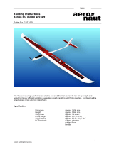
alpha junior specifications
Wingspan: 2100 mm
Fuselage length: 1130 mm
Wing area (FAI): 46 dm²
Weight, according to
finish and fittings: 1100 - 1600 g
Wing loading (FAI): min. 24 g / dm²
Wing section: SD 8040 mod.
Tailplane section: flat plate
alpha club specifications
Wingspan: 2700 mm
Fuselage length: 1315 mm
Wing area (FAI): 63 dm²
Weight, according to
finish and fittings: 1600 - 2100 g
Wing loading (FAI): min. 26 g / dm²
Wing section: SD 8040 mod.
Tailplane section: flat plate
RC functions
Elevator 1 servo min. 15 Ncm
Rudder 1 servo min. 15 Ncm
Ailerons (junior option) 2 servos min. 15 Ncm
Landing flaps (optional) 2 servos min. 15 Ncm
Receiving system components
The fuselage is designed to accept the “EinStein” module,
MPX # 1 4004, for the elevator and rudder. Alternatively you
can use two small servos, e.g. Micro 3BB, MPX # 6 5049.
The wings are designed to accept two MS-X3 servos, MPX #
6 5035, in each wing for the ailerons and landing flaps.
It is important that the receiver battery should be of
generous capacity to cope with the model’s receiving system,
bearing in mind that you will be using up to six servos. We
recommend a 600 mAh pack: 4 cells SCR-C, MPX Order No. 15
5553, or four 1000 mAh cells, MPX # 15 5566. Extra battery
capacity always makes more sense than lead ballast.
If you are using an “EinStein” module no separate switch
harness is required, as the switch is built-in. If you are using
a conventional receiver we recommend a switch harness
with charge socket, MPX Order No. 8 5139.
We strongly recommend that you also fit some form of
receiver battery monitor. MULTIPLEX offers a comprehensive
range:
Receiver battery tester Order No. 8 5541
Receiver battery alarm Order No. 8 5104
Receiver battery monitor Order No. 7 5160
If you prefer a conventional receiver we recommend the
Micro 5/7, MPX # 5 5933.
For the electrical connection between the wing-mounted
servos and the fuselage we recommend the Cable Set 2, MPX
Order No. 8 5255.
A similar cable set fitted with Universal (UNI) connectors is
available under MPX 8 5253.
Important note - e.g. when repairing the D-box
For all joints involving the styrofoam D-box leading edge
it is essential that you do not use solvent-based adhesives,
and in particular avoid instant or cyano-acrylate glue
(cyano, or CA). These materials will melt and destroy a
large volume of foam, and the component will be
completely ruined. Use solvent-free adhesives, such as 5-
minute epoxy or white glue.

14
For all other joints any standard modelling adhesive can
be used. We recommend in particular our wide range of
MULTIPLEX - ZACKI instant “cyano” glues, which includes
adhesives of different viscosity, fillers and cleaners. Use
ZACKI if you want construction to proceed easily,
smoothly and fast. Be sure to read the instructions
supplied with these materials.
Notes on using epoxy
Epoxy laminating resin is not an effective adhesive as it
stands. However, you can make a variety of excellent
adhesives by mixing additives into it. By careful choice of
filler you can match the characteristics of the adhesive to the
requirements of the moment.
1. Chopped cotton fibres, Order No. 60 2738, produce a
tough but flexible joint.
2. Superfine glass fibres, Order No. 60 2784, produce a
rock-hard joint.
3. Micro-balloons, Order No. 60 2779/80, convert the resin
into a lightweight filler paste.
4. The special thixotropic agent, Order No. 60 2782, makes
all the adhesives and fillers listed above thixotropic, i.e.
prevents them running off a vertical surface.
The alpha junior / club
The kit you have just purchased includes every item you
need to complete the basic airframe, including linkage
hardware, but does not include adhesives.
You can make a significant contribution to the model’s
ultimate performance and appearance by building accurately,
carefully and patiently. A badly built model usually flies
badly and is hard to control. An accurately built and well
trimmed model will reward you with high performance,
docile handling and a pleasing appearance, and will give
pleasure to pilot and onlooker alike. Take your time - the
effort is well worth while. These building instructions have
been designed to help you get the best out of the kit, so
please follow the procedures and the sequence of assembly
described as accurately as possible.
MULTIPLEX model kits are subject to constant quality checks
throughout the production process, and we sincerely hope
that you are happy with the contents of your kit. However, we
would ask you to check all the parts before you start
construction, as we cannot exchange components which
you have already worked on. If you find any part is not
acceptable for any reason, we will readily correct or exchange
it once we have examined it. Just send the component to our
Model Department. Please be sure to include a brief
description of the fault.
The alpha junior is a rudder/elevator glider which can easily
be converted to a three-axis machine.
The alpha club is the ideal model for the week-end flyer who
is keen to move up from rudder/elevator to a three-axis
machine.
Both models can also be converted to electric power simply
and quickly.
... so let’s get down to work.
Fuselage
We will start by completing the fuselage, as this is the
reference point for all the other components.
The first step is to decide whether to complete your model as
a pure glider or an electric-powered glider. Either model can
easily be converted to electric power by fitting the
appropriate electric conversion set, consisting of motor /
propeller / spinner / motor bulkhead and wooden parts.
The vacuum-moulded template required for removing the
fuselage nose is supplied in the kit.
alpha junior electric conversion set # 21 4133
MULTIcont 40/16 BEC MPX speed controller # 7 2252
7/1700 mAh battery # 15 5646
alpha club electric conversion set # 21 4131
MULTIcont 40/16 BEC MPX speed controller # 7 2252
10/1700 mAh battery # 15 5534
Removing the fuselage nose
Tack the vacuum-moulded template 9 (club / junior) to the
nose of the fuselage using a few drops of cyano, and carefully
remove the nose by sawing round the moulded-in flange
using a hacksaw blade.
Fig. 1
Trimming the motor bulkhead (included in the electric
conversion set)
The next step is to check that the fuselage follows the shape
of the spinner accurately, and this is done with the help of the
motor bulkhead E-01. Screw the motor to the motor bulkhead,
fit the propeller hub and spinner on the motor shaft, and
carefully trim the bulkhead to fit in the fuselage. Sand back
the bulkhead to the point where the spinner can be lined up
as accurately as possible with the contours of the fuselage
nose. The correct sidethrust and motor downthrust are
defined by the template, and should not be altered.
Roughen the inside of the fuselage with 80-grit abrasive
paper where it mates with the motor bulkhead. With the
motor and spinner still attached, glue the bulkhead in the
fuselage using a little 5-minute epoxy. Leave the resin to set
hard.
Carefully remove the motor again and apply a generous fillet
of thickened epoxy (use super-fine glass fibres, MPX # 60
2784) all round the joint on both sides. Be fairly sparing with
the epoxy on the motor side, otherwise you could find
problems when re-installing the motor.
Fig. 2
Cooling slots
Mark the position of the three cooling air slots on both sides
of the fuselage using a pencil. A template for the slots is
printed in these instructions.
Cut the cooling slots by drilling a series of closely-spaced 3
mm Ø holes, then filing them out carefully to final size.
Fig. 3
Making and installing the battery holder
Assemble the flight battery holder from the wooden parts E-
02, E-03 and E-04, and glue the parts together. Glue the block
E-05 to the underside of the battery holder at the front and fit
the screw E-06 to reinforce the joint. Sand the block E-05 to
follow the curvature of the fuselage, and place the battery
holder temporarily in the fuselage. Ensure that the holder
does not foul or damage the bowden cables, and adjust their
position if necessary. Before finally gluing the battery holder
in position check the model’s Centre of Gravity, as you can

15
move the flight pack forward or aft at this stage to correct any
discrepancy. When everything fits correctly glue the battery
holder to the fuselage, applying thickened epoxy to both
sides at the rear and to the block E-05 at the front. Remember
to roughen the inside of the fuselage beforehand using 80-
grit paper.
Fig. 4
The flight pack is held in place as follows: at the rear the
battery engages under the retaining strap and at the front it
is attached using a strip of Velcro (hook-and-loop) tape.
Note that the adhesive on the Velcro tape does not stick very
well to bare wood, so you will need to fix the hook tape to the
plate using cyano.
Towhook support block (glider)
The towhook support block 10 should be epoxied in place at
this early stage while accessibility is still good. Measure the
hook position aft of the extreme point of the nose on the
underside of the fuselage using a tape measure:
for the alpha junior: 345 mm
for the alpha club: 385 mm
Drill a central x mm Ø hole at this point and seal it off on the
outside with a strip of tape. Roughen up the inside of the
fuselage at the block position using 80-grit abrasive paper.
Glue the towhook block 10 centrally over the hole using
thickened 5-minute epoxy.
Fig. 5
Completing the canopy
The canopy is supplied ready-made, but you may have to
trim it slightly. Remove all rough edges from the steel pin 42
and round off one end. Glue the prepared pin 42 in the
channeled wooden rail 14, then glue the channeled rail
centrally to the canopy using thickened 5-minute epoxy. The
actual canopy retainer consists of the steel spring 53 which
has to be bent to the shape shown. Fit the canopy plate 13
over the spring, and fix both parts to the canopy using 5-
minute epoxy after roughening the joint surfaces with 80-
grit abrasive paper.
Fig. 6
Trim the cross-piece 17 to fit in the rear part of the canopy
and glue it in place to stiffen that area of the moulding.
Wing joiners
The wing joiners consist of two 6 mm Ø steel rods 29. When
the model has been completed the rods should be glued
permanently in the outboard wing panels to prevent any risk
of them becoming lost. We recommend thick cyano for this.
Cut the incidence pegs 15 to a length of about 30 mm and
glue them in the trailing edge of the outboard panels, leaving
half their length projecting. You will need to drill out the
dowel holes to 4 mm Ø.
Wing retainers
When the outboard wing panels have been fitted, they must
be prevented from shifting in flight. The simplest method is
to apply a piece of adhesive tape over the joint.
The most convenient method is to fit the MULTIlock system,
MPX # 72 5138. These systems are supplied with full
installation instructions.
Fig. 7
Wing / fuselage fit
The wing is attached to the fuselage using two screws 30 and
31 and the washer 33. The threaded sleeves for the screws are
factory-fitted in the fuselage.
Trimming the canopy to fit the wing
You may need to trim the top rear end of the canopy to follow
the curvature of the wing when the wing is screwed to the
fuselage. Work carefully, as it is very easy to file away too
much material.
Fuselage slot for rudder bowden cable
The position of the slot is marked at the transition point
between the rudder and fuselage. Drill a series of 2 mm Ø
holes at the marked point and then file them out to form a
slot about 2.5 - 3 mm wide using a needle file. Remove rough
edges from the bowden cable 51 and slip it into the bowden
cable inner tube 52. Fit the bowden cable inner into the outer
sleeve in the fuselage from the front, route it out of the slot
and check that it slides smoothly. Trim the slot if necessary.
Remove the bowden cable again when you are satisfied.
Fig. 8
Completing the tailplane
The tailplane is designed to be removable for ease of
transport. It is attached to the fuselage using the locating
dowel 15 at the front and a screw 32 and washer 34 at the
rear. The first step is to align the tailplane with the wing with
the help of the support plate 16. First drill a 4.5 mm Ø hole at
the appropriate point in the support plate, and then attach
the wing to the fuselage. Check that the parts line up correctly,
then glue the support plate to the underside of the tailplane
using thickened epoxy. Align the wing and tailplane carefully
once more, and support the tailplane accurately until the
glue has set hard.
Mark the position of the locating dowel on the fuselage and
drill a 4 mm Ø hole at that point. Cut the dowel to a length of
25 mm, ensure that it fits snugly in the channel in the tailplane,
and check alignment once more. The dowel can then be
glued permanently to the tailplane.
Uncovered version: sand the tips and leading edge of the
tailplane to a rounded section as shown.
Fig. 9
Attaching the fin to the fuselage
Check that the fin is a snug fit in the slot in the fuselage; you
may need to clean up the inside faces of the slot using a
needle file. Slide the fin down into the fuselage until its
bottom face rests squarely on the bottom of the fuselage.
Screw the tailplane to the fuselage, and check that it is
possible to set the fin at exactly 90° to it.
Glue the fin in the fuselage, set it exactly upright and tape it
in place while the glue is setting. Caution: don’t allow excess
epoxy to get into the rudder bowden cable and jam it.
Fig. 10
Installing the “EinStein” module in the fuselage (glider)
This module integrates a 7-channel receiver, 2 servos and a
switch, and we particularly recommend it for the alpha
junior / club. It consists of a high-quality 7-channel FM receiver
and two micro-size servos in a single case.
The unit is easy to fit, and takes only a few minutes to install.
Fit the receiver battery (4/600 mAh, MPX # 15 5533, or 4/1000
mAh, MPX # 15 5566) in the extreme nose of the fuselage.
Roughen the inside of the fuselage bottom just aft of the

16
battery using 80-grit abrasive paper. Mark the position of the
“EinStein” and its mounting plate inside the fuselage, then
glue the mounting plate to the bottom of the fuselage using
thickened epoxy.
Fig. 11
Tip: to recharge the receiver battery it is necessary to
disconnect the plug from the “EinStein” module. You can
make the connector easier to reach by gluing a small piece of
scrap wood or similar to it as a handle, pointing straight up.
Installing conventional RC components in the fuselage.
As an alternative to the “EinStein” you can install two Micro
3 BB servos, MPX # 6 5049. For this configuration you will
need parts 11 and 12.
Glue the two servo mounting blocks 12 to the servo plate 11,
spaced 33 mm apart (servo case length). Mark the position of
the retaining screw holes on the blocks, drill them and screw
the servos in place. Fit the receiver battery (4/600 mAh, MPX
# 15 5533, or 4/1000 mAh, MPX # 15 5566) in the extreme nose
of the fuselage. Mark the position of the rear end of the
battery on the bottom of the fuselage, and roughen the
inside of the fuselage bottom just aft of that point using 80-
grit abrasive paper. Glue the servo plate to the bottom of the
fuselage using thickened epoxy. The receiver can be attached
to the fuselage using Velcro tape.
For this version you will need a separate switch, and we
recommend the switch harness with charge socket, MPX
# 8 5100.
Fig. 12
Installing the receiver battery
The receiver battery is held in place in the fuselage nose
using Velcro tape (MPX # 68 3112) and foam packing or
similar. At the top fit a piece of foam rubber or styrofoam
between the fuselage and the battery to prevent it moving.
In the electric version a separate receiver battery is not
required provided that you use a suitable BEC speed
controller, as the servos and receiver are powered by the
flight battery.
Completing the fuselage linkages
Remove any rough edges from the rudder pushrod 51 and
slip it into the bowden cable inner tube 52. Slip the inner into
the outer sleeve in the fuselage, and bend it slightly in the
desired direction if necessary. At the rudder end solder or
epoxy a clevis 36 to the pushrod (use UHU plus Endfest 300
slow-setting epoxy). Sand the end of the steel rod thoroughly
before gluing or soldering.
Connect the clevis to the rudder horn 39 and mark the
position of the horn on the rudder. Drill holes for the retaining
screws, and fix the horn in place using the spreader plate 40
and two screws 41. Check that full rudder movement is
available to both sides, and make adjustments if necessary.
Screw a locknut 38 and a clevis 36 onto the threaded coupler
37 and connect the clevis to the servo output arm. Cut the
pushrod to the correct length at the servo end, taking into
account the depth of the coupler socket, and sand the end
thoroughly. Set the elevators to neutral and solder or epoxy
the threaded coupler to the pushrod.
The elevator linkage is based on the steel pushrod 50.
Complete it by repeating the procedure described for the
rudder linkage.
Locate the channeled rail 14 which supports the bowden
cables at the front end of the fuselage, trim it to fit and glue
it to the fuselage sides.
Final work on the fuselage
Screw the towhook 35 to the fuselage.
Slip the receiver aerial into a spare bowden cable sleeve, tie
a knot at the end and lay the tube in the fuselage tail boom.
It does not need to be fixed in place.
Tip: to draw the aerial through the tube, first glue the end of
the aerial to a length of 0.6 mm Ø spring steel wire with a
drop of cyano, then pull the wire through the sleeve.
Completing the wing
At this point you have to decide which control surfaces on
the wings are to be radio-controlled.
The wing of the alpha junior is factory-prepared in such a
way that it is a simple matter to separate the ailerons and
landing flaps and link them to the RC system.
The ailerons and flaps can also be left in place initially if you
prefer, and linked up at a later date, i.e. after you have flown
the model for a while. The alpha club is designed for aileron
control from the outset.
There are two methods of slowing the model for the
landing approach:
If you have a suitable radio control system (with mixers) you
can set the ailerons to rise together to provide glide path
control. However, this type of brake is not very effective on
these models, and it is much better to use the landing flaps
incorporated in the inboard wing panels.
Installing the wing-mounted servos
The wings are factoroy-prepared to take the servos. The first
step is to cut away the covering film on the underside of the
wing at the servo position. Solder the end of the servo lead
(e.g. cable set, MPX # 8 5255) to a length of steel piano wire
and thread it through the holes in the wing ribs.
Place the servo (e.g. MS-X3 servo, MPX # 6 5035) in a piece of
heat-shrink sleeving and shrink the sleeve round it. Sand the
joint surface of the plastic sleeve and glue it in the wing using
5-minute epoxy. Connect the wires as described in the
instructions supplied with the cable set, and glue the socket
to the facing rib of the wing panel. When the glue has set
hard apply a strip of tape over the socket. Wax the tape and
polish it off with a soft cloth. Now push the plug into the
socket, apply thickened 5-minute epoxy to the plug and
push the wing panels together so that the plug is glued to
the other wing panel. The servo connector now engages
automatically, and the system is simple to install and works
reliably.
Cut out the servo fairing 8 and attach it with hinge tape after
connecting and adjusting the mechanical linkage.
Fig. 13
Separating the ailerons and/or landing flaps
Separate the control surfaces from the wing by sawing parallel
to the fuselage centreline using a metal-cutting blade to
produce a fine, clean cut. Place a ruler along the hinge line in
the spanwise direction, and cut through the connecting
piece with a sharp balsa knife. Sand the hinge line surface
completely flat using a sanding block, and apply adhesive
tape to the bare wood to seal it after ironing down any loose
edges of the film covering along the hinge edge using a film
iron. The aileron or flap can now be attached to the wing
using hinge tape, MPX # 70 3205. The best method is to apply
a single strip centrally along the top pivot line, then fold the
control surface up and over before applying a second strip
on the inside of the hinge.
Fig. 14

17
Actuating the ailerons and/or landing flaps
The linkage to each control surface is based on a pre-formed
steel rod 42, a threaded coupler 37, a locknut 38 and a clevis
36. The connection to the control surface is by means of the
screw-fitting horns 43, spreader plates 40 and two screws 41.
If you decide to actuate the supplementary control surfaces,
the linkage components required are to be found in the
MULTIPLEX accessory range.
Fig. 15
Uncovered version: at this point the bare wooden parts
have to be covered, and for this we recommend iron-on film.
Please refer to the appendix for details of the covering
procedure, together with many useful hints and tips.
Leave the trailing edge about 1 - 1.5 mm thick and “square”.
Don’t round off the trailing edge, as the thicker, sharp-edged
trailing edge is almost as efficient as a razor-sharp one, but is
much more durable for general flying, especially if film-
covered.
The basic structure of the model is now complete.
Electrical connection, wing / fuselage
The alpha junior / club has up to four wing-mounted servos
which have to be connected to the receiver. They are
connected at the fuselage / wing transition using grey 5-pin
MPX plugs and sockets.
It is important that all the wing-mounted servo cables should
be fitted with separation filters. Cable sets including all the
parts required together with detailed instructions are
available under the following Order Numbers:
Cable Set MPX 8 5255 (2 x)
Cable Set UNI 8 5253 (2 x)
Be sure to select the best quality connectors you can find.
Stick to genuine MPX connectors with gold-plated
contacts!
Connect all the positive wires to a common connector pin,
and do the same with all the negative wires to a different pin.
A separate contact is required for each signal wire.
If you have to connect two servos for each wing you will need
to use four contacts of the 5-pin plug (1 x positive, 1 x
negative and 2 x signal).
The connectors are installed “loose”, i.e. the plugs (wings)
and sockets (fuselage) are not glued in place permanently.
Always grasp the connector by the plastic body when
disconnecting - don’t pull on the wires!
Remember to mark the plugs and sockets L and R to avoid
confusion at the flying site (use a waterproof felt-tip pen).
Cut an opening for the cables at a suitable point in the
fuselage wing saddle. This is best done by drilling a series of
holes close together, then linking the holes with a hacksaw
blade and filing out to size. Avoid sharp or rough edges, keep
all radii large, and don’t make the hole larger than is necessary.
[Fig. 16]
Your model is now complete.
Nevertheless, there are a few important points to be checked
while you are still in the workshop:
Centre of Gravity (balance point) and longitudinal dihedral.
Provided that you get these two settings right you will
encounter no problems in test-flying your new model and in
general flying.
Successful test flying always boils down to good
preparation.
At Multiplex the CG and longitudinal dihedral are first
determined theoretically, then confirmed by practical flight
testing.
Centre of Gravity: alpha junior 60 mm
alpha club 70 mm
The easy way of checking this accurately it to use the Centre
of Gravity balance, MPX Order No. 69 3054.
A longitudinal dihedral of 2º has proved just right for these
models, and this can be checked using the incidence gauge,
MPX Order No. 69 3053.
We strongly recommend that you stick to these settings. The
control surface travels stated below have been established
as the ideal values during practical test flying, and have been
confirmed by several experienced model pilots. Set these
travels for the time being, and alter them as and when you
see fit. We are confident that you will never need to change
them.
Control surface travels
All control surface travels are measured at the widest point
of the surface, and are stated below in millimetres.
Control surface travels, alpha junior
left / right mm
Rudder servo Rudder 20 20
down / up mm
Elevator servo Elevator 7 10
down / up mm
Aileron servos (optional) Ailerons 8 12
down / up
Landing flap servos (optional) 90º 0
Control surface travels, alpha club
left / right mm
Rudder servo Rudder 20 20
down / up mm
Elevator servo Elevator 7 10
down / up mm
Aileron servos Ailerons 8 12
down / up
Landing flap servos (optional) Landing flaps 90º 0
Now your alpha junior / club is ready for the air!
Preparing for the first flight
“Old hands” will now be waiting for the first opportunity to
take their new alpha junior / club to the flying site, where
they will test-fly it in the accustomed manner, carry out any
minor corrections required, and then, we hope, have many
hours of pleasure flying their new model.
The following is intended to help the less experienced
modeller to test-fly and trim the model correctly, and to
exploit the model’s fine performance to the full.
Test flying
Every flying machine, from the humble chuck glider to the
full-size aircraft, has to be test-flown and trimmed after
completion; your alpha junior / club is no exception. The
slightest inaccuracy in construction can lead to a minor
variation in the model’s flight characteristics and control
response. Test flying is the process of optimising the CG, and
of fine-tuning the model’s control response.
Avoid at all costs repeated hand-glides on a flat site. The

18
most dangerous time for any model is when it is close to the
ground, and hand launches are therefore by their nature
extremely hazardous. There is hardly any time to correct the
controls, and a hard landing can easily damage the model.
Range testing (for experts too!)
Ensure that your transmitter and receiver batteries are freshly
charged according to the battery manufacturer’s
recommendations. Before switching on your transmitter
make certain that your channel is vacant. The channel pennant
on your transmitter aerial is obligatory, and shows other
pilots what frequency you are using. If there are other pilots
present, tell them loud and clear what channel you are on,
and find out what frequencies they are using.
Before the first flight you should carry out a range check, and
we strongly recommend that you repeat the test before the
start of every day’s flying. Hold the model in such a way that
your body cannot influence the receiver aerial, i.e. hold it by
the fuselage nose.
Your assistant should collapse the transmitter aerial fully
(but leave it attached), then walk away from you carrying the
transmitter.
As the range increases your assistant should operate one
transmitter function constantly while you watch the model’s
control surfaces. The servos not being moved should remain
motionless up to a range of about 80 m, and the moving
servo should follow the stick deflections immediately and
smoothly.
This test can only be carried out successfully if the radio band
is not suffering interference, and if no other RC transmitters
are switched on - even on different channels! Note that in
high mountain areas extreme field strengths and excessive
range of other transmitters makes such checking procedures
worthless.
If you are not sure the system is working correctly, please
don’t risk a flight - even if you are dying to fly the new glider
and your mates are egging you on. Check first that your
channel really is vacant. If so, and if the problem persists,
pack up your entire RC system (complete with batteries,
switch harness and servos) and send it back to the equipment
manufacturer for checking.
Faults don’t cure themselves!
The first flight
The first flight can be carried out in any of several ways - at the
slope from a hand-launch, at a flat field using a bungee
system or winch. If you have fitted an electric power system
the model has to be hand-launched.
For the first flight ask an experienced modeller to launch for
you, so that you have both hands on the sticks right from the
outset.
Adjust the trims as necessary once the model is at a safe
altitude: straight and level flight at cruise speed is the first
aim. The next step is to fly turns alternately to left and right
to check the model’s turning characteristics, the
harmonisation (balance) between ailerons, elevator and
rudder, and the aileron differential. Be sure also to lower the
landing flaps (or raise the ailerons) so that you have a chance
to see the resultant change in pitch trim.
If you still have plenty of height you should check the Centre
of Gravity right at this early stage. The procedure for CG
testing described here is a method of fine-tuning the model’s
balance. It can only work when air movements are slight, and
when the initial CG position is approximately correct. It is
bound to fail if the model is way out of balance and/or there
is a strong wind. In windy conditions it is difficult to set up the
model for normal cruise speed, as it is hard to judge the
model’s speed relative to the surrounding air.
Now - assuming that you have plenty of height in hand -
apply full down-elevator briefly to place the model in a
vertical dive. Immediately centre the stick and watch the
model carefully. If it recovers to normal flight in a broad,
gentle curving arc (30 - 40 m) by itself, without ballooning up
above the horizontal, then the CG is correct.
If the model bounces up again immediately and climbs
strongly, the CG is too far forward. If possible move the flight
battery slightly further aft to move the CG back. If not,
remove a little lead ballast (about 30 g) from the nose, apply
slight down-trim, and repeat the test.
If the model shows no tendency to recover by itself - the dive
may even become steeper - the CG is too far aft. Immediately
recover the model with gentle up-elevator. If possible move
the flight battery slightly further towards the nose to move
the CG forward. Add a little lead (min. 20 g, max. 40 g) to the
fuselage nose, fix it securely, and apply a little up-trim.
Repeat the test.
Safety
Safety is the First Commandment when flying any model
aircraft. Third party insurance should be considered a basic
essential. If you join a model club suitable cover will usually
be available through the organisation. It is your personal
responsibility to ensure that your insurance is adequate.
Make it your job to keep your models and your radio control
system in perfect order at all times. Check the correct charging
procedure for the NC batteries used in your RC set. Make use
of all sensible safety systems and precautions which are
advised for your system. An excellent source of practical
accessories is the MULTIPLEX main catalogue, as our products
are designed and manufactured exclusively by practising
modellers for other practising modellers.
Always fly with a responsible attitude. You may think that
flying low over other people’s heads is proof of your piloting
skill; others know better. The real expert does not need to
prove himself in such childish ways. Let other pilots know
that this is what you think too. Always fly in such a way that
you do not endanger yourself or others. Bear in mind that
even the best RC system in the world is subject to outside
interference. No matter how many years of accident-free
flying you have under your belt, you have no idea what will
happen in the next minute.
The fascination of it all
Model flying is, and always has been, a fascinating hobby,
and a thoroughly enjoyable way of spending your leisure
hours. Take your time to get to know your new alpha junior
/ club really well. Plan to spend many hours in the open air,
where you will learn to appreciate the model’s outstanding
performance and its docile handling. You can join us in
enjoying one of the few types of sport which combine high
technology, manual dexterity, and sophisticated personal
skills. You can fly alone or with friends, and at the same time
you can enjoy the pleasures of nature - treats which have
become rare in today’s world.
We - the MULTIPLEX team - wish you many hours of pleasure
in building and flying your new model. Happy landings!
MULTIPLEX Modelltechnik GmbH
Model Development Dept.

19
Appendix
Covering with heat-shrink film is the quickest and most
effective finishing method, and gives outstanding results in
terms of appearance, practicality and durability. The main
MULTIPLEX catalogue includes illustrated instructions on
film covering, and we suggest that you read this text in
conjunction with the instructions included with the film.
Learning how to apply film is not difficult; provided that you
follow the instructions to the letter even your first wing will
be a complete success.
Important:
When covering with iron-on film it is essential to ensure
that the foam core is not overheated, as this can result in
damage (distortion). Some films require a high processing
temperature, and if you are using these types of film you
must take particular care when applying the material.
If you use iron-on film you will obtain good results without
any problems.
Important:
Under the skin of the D-box is a styrofoam core, which
becomes flexible if it reaches a temperature of about
90°C. If overheated the material may distort, and if this
happens the result will be dents and bulges, and there is
nothing you can do to cure it. Naturally we cannot
exchange wing panels which have been damaged in this
way, and we beg your understanding in this respect.
No matter how carefully you sand the surface and remove
every trace of dust with a stiff brush, you cannot remove the
wood’s natural grain texture. When you rub the warm film
down with a soft cloth, the material is pressed into the
surface texture, and inevitably follows the microscopic ridges
and grooves of the wood. The result is a less smooth surface
than you might have expected.
This effect can be eliminated in the following way: instead of
the soft cloth, take a thick piece of balsa - similar to a sanding
block - and stretch a piece of stiff fabric over it as follows:
place the block on the fabric, pull the sides up, and staple the
material down on the top of the block. If you now rub the film
down with the smooth side of this block (your hand will be a
comfortable distance from the heat gun) the film will not
follow the tiny grooves in the wood, and you will usually
achieve a highly efficient super-smooth surface, approaching
that of a moulded GRP wing panel.
The ailerons and camber-changing flaps are usually attached
to the wings with hinge tape. However, it is possible to use
the film itself as a hinge. The result can be every bit as good
as a tape hinge. This is only possible if you have followed the
instructions to the letter and produced really sharp, perfectly
straight mating edges on the wing and the control surface.
The top and bottom film must weld together along the pivot
line, and this is only possible if the edges are really sharp.
The first step is to cover the underside of the wing in the usual
way. Apply film to the control surface as well, but do not
finish the job; simply tack down the edges, trim the film to
size, and iron the edges down (i.e. do not use the heat-gun).
Leave excess film at the ends and especially at the front (at
least 5 cm). Pull the excess round the ends, iron it down and
trim it off neatly. You now have a control surface sitting on
the bench, underside film-covered, not yet shrunk, and with
a wide excess of film running along the whole length of the
leading edge.
Place the wing on the bench resting on its leading edge, top
surface facing you; support it in this position. Lay the
projecting film on the wing recess sealing strip and pull it
tight, so that the flaperon hangs down, resting on the top
surface of the wing. Centre the control surface in the recess
and spot-fix the film in place using the tip of the iron. Set the
aileron to neutral (centre) and check the end gaps in the wing
recess. You may find that several attempts are necessary to
obtain identical end gaps. Pull the film taut so that the
aileron is pulled into the correct position against the wing,
and iron the film into place. Cut off the excess film and iron
the edge down permanently. If the control surface is now
brought to the neutral position it should be possible to see
a narrow strip of film between wing and control surface from
above. Fold the control surface onto the top of the wing
again and shrink the film on the underside of the control
surface. This protects the underside of the wing from heat.
Cover the top surface of the wing in the usual way. Trim the
film and iron down the cut edges. Iron the film down firmly
on both sides of the hinge line, then cut through the film on
both sides of the gap from the underside, using a very sharp
knife. The control surface will now be free to move again.
Now comes the most important step: iron down the film 5
mm from the pivot line on the wing and the control surface,
holding the control surface in the extreme “down” position.
After this run the iron over the whole of the pivot line to weld
the bottom film to the top film. Fold the control surface right
up and back, and repeat the process on the underside.
When finishing the job with the heat gun, take a little care
when working close to the control surface to avoid loosening
the film hinge. If it does come loose you will need to repeat
the last stage. When you are finished, the control surface will
be hinged permanently and invisibly to the wing, and will
move freely up and down.
[Fig. 17]
Applying the decals
Cut out the decals and apply them to the model.
There are two convenient methods of applying the individual
transfers included in the decor set, both of which enable you
to position the transfer accurately: the strip method and the
water method.
For smaller items we recommend the strip method: using
sharp scissors cut out the transfer, leaving an even excess
about 1 - 2 mm wide all round. Release the backing paper on
one edge and cut a strip about 5 mm wide from it. Place the
transfer on the model and position it carefully, holding the
exposed strip away from the surface. When you are happy,
press the exposed strip down. Fold the transfer back on itself
so that you can peel off the remaining backing paper starting
from the stuck edge. At the same time rub the transfer down
onto the model with your other hand, starting from the edge
already in place.
For larger transfers the strip method can only be
recommended to the highly skilled modeller; generally
speaking the water method is safer. The surface to be
decorated must be waterproof. Mix a squirt of household
liquid detergent into a bowl of water, and dampen the
surface of the model with the solution. Cut out the transfer as
before, and remove about one third of the backing paper.
Position the transfer carefully, then peel away the remaining
backing paper. Lay the transfer down on the model. You will
find that the water prevents the adhesive sticking, and the
transfer can be moved around to position it accurately. Wipe
out any air bubbles and excess water, working from the
centre of the transfer outwards. The residual moisture will
diffuse away in a day or two, after which the transfer will
adhere in the usual way. In the meantime it is best not to
touch the transfer.

20
alpha junior
uncovered # 21 4021
alpha junior
factory-covered # 21 4132
alpha club*
uncovered # 21 4022
alpha club*
factory-covered # 21 4130
Parts list
Part No. Description Purpose Material dimensions
No. off
1 1 Building instructions A4
2 1 Name placard decal set Printed film Ready made
3 1 Epoxy fuselage White GRP Ready made
4 1 Wing set (3-part) Foam/obechi/balsa Ready made
5 1 Tailplane and elevator Balsa Ready made
6 1 Fin and rudder Balsa Ready made
7 1 Vacuum-moulded canopy Plastic Ready made
8 1 Servo fairing Plastic Ready made
9 1 Fuselage nose template Plastic Ready made
Wooden parts
10 1 Towhook block Fuselage Spruce 10 x 10 x 40 mm
11 1 Servo plate Fuselage Plywood 3 x 32 x 50 mm
12 2 Servo mounting block Fuselage Obechi 6 x 23 x 32 mm
13 1 Canopy plate Canopy Plywood 3 x 15 x 30 mm
14 3 Channeled rail Canopy / bowden cable Obechi Ready made, 40 mm
15 1 Dowel Tailplane / wing Beech 4 Ø x 100 mm
16 1 Support plate Tailplane Plywood 1.5 x 25 x 100 mm
17 1 Cross-piece Canopy Obechi 5 x 10 x 70 mm
Accessories
29 2 Wing joiner Wing GRP 6 Ø x 120 mm
30 1 Screw Wing Plastic M5 x 20 mm
31 1 Screw Wing Plastic M5 x 50 mm
32 1 Screw Tailplane Plastic M4 x 25 mm
33 1 Washer Wing Plastic Ready made, M5
34 1 Washer Wing Plastic Ready made, M4
35 1 Towhook Fuselage Steel Ready made
36 4/8* Metal clevis Linkage Steel M2
37 2 Threaded coupler Linkage Brass M2
38 2/4* Hexagon nut Linkage Brass M2
39 2 Horn, 3 holes Elevator / rudder Plastic Ready made
40 2/4* Horn spreader plate Linkage Plastic Ready made
41 4/8* Horn fixing screw Elevator/rudder/aileron Steel M2 x 12 mm
42 1 Locating pin Canopy Spring steel 3 Ø x 40 mm
43 2* Pre-formed pushrod Aileron linkage Steel 1 Ø x 85 mm
44 2* Horn, 2 holes Ailerons Plastic Ready made
Wire set, alpha junior
50 1 Elevator pushrod Linkage Spring steel 1.3 Ø x 1000 mm
51 1 Rudder pushrod Linkage Spring steel 0.8 Ø x 850 mm
52 1 Bowden cable inner tube Rudder linkage Plastic 2/1 Ø x 1000 mm
53 1 Steel rod retainer Canopy Spring steel 1.3 Ø x 250 mm
Wire set, alpha club
50 1 Elevator pushrod Linkage Spring steel 1.3 Ø x 1200 mm
51 1 Rudder pushrod Linkage Spring steel 0.8 Ø x 1100 mm
52 1 Bowden cable inner tube Rudder linkage Plastic 2/1 Ø x 1000 mm
53 1 Steel rod retainer Canopy Spring steel 1.3 Ø x 250 mm
* alpha club
/