Page is loading ...

Installation and Assembly:
PRG Precision Gear Projector Mount with Universal
Adapter Plate
Features:
• ImageLock
TM
alignment prevents picture sag or
drift
• Exclusive aluminum track quick release
Models: PRG-UNV, PRG-UNV-S, PRG-UNV-W
ISSUED: 09-30-09 SHEET #: 056-9024-5 07-18-11
2300 White Oak Circle • Aurora, Il 60502 • (800) 865-2112 • Fax: (800) 359-6500 • www.peerlessmounts.com
Max UL Load Capacity:
50 lb (22.7 kg)

2 of 51
ISSUED: 09-30-09 SHEET #: 056-9024-5 07-18-11
NOTE: Read entire instruction sheet before you start installation and assembly.
Table of Contents
Parts List................................................................................................................................................3
Projector Mount Assembly Installation................................................................................................4-7
Attaching Adapter Plate to Projector...................................................................................................... 9
Accessories ...................................................................................................................................15, 16
Tools Needed for Assembly
• stud fi nder ("edge to edge" stud fi nder is recommended)
• phillips screwdriver
• drill
• 5/16" bit for solid concrete surface
• 5/32" bit for wood studs
• open end wrench
• level
• Do not begin to install your Peerless product until you have read and understood the instructions
and warnings contained in this Installation Sheet. If you have any questions regarding any of the
instructions or warnings, for US customers please call Peerless customer care at
1-800-865-2112, for all international customers, please contact your local distributor.
• This product should only be installed by someone of good mechanical aptitude, has experience
with basic building construction, and fully understands these instructions.
• Make sure that the supporting surface will safely support the combined load of the equipment and
all attached hardware and components.
• Never exceed the Maximum UL Load Capacity. See page one.
• If mounting to wood joists ceilings, make sure that mounting screws are anchored into the center
of the studs. Use of an "edge to edge" stud fi nder is highly recommended.
• Always use an assistant or mechanical lifting equipment to safely lift and position equipment.
• Tighten screws fi rmly, but do not overtighten. Overtightening can damage the items, greatly
reducing their holding power.
• This product is intended for indoor use only. Use of this product outdoors could lead to product
failure and personal injury.
• This product was designed to be installed on the following wall construction only;
WALL CONSTRUCTION HARDWARE REQUIRED
• Wood Stud Included
• Wood Joist Included
• Solid Concrete Included
• Brick Contact Qualifi ed Professional (Not Evaluated By UL)
• Other or unsure? Contact Qualifi ed Professional
WARNING

3 of 51
ISSUED: 09-30-09 SHEET #: 056-9024-5 07-18-11
PRG-UNV PRG-UNV-S PRG-UNV-W
Description Qty. Part # Part # Part #
A projector mount assembly 1 054-1171 054-4171 054-2171
B adapter plate 1 055-1938 055-4938 055-2838
C concrete anchor 2 590-0320 590-0320 590-0320
D #14 x 2-1/2" phillips hex head wood screw 2 5S1-015-C03 5S1-015-C04 5S1-015-C04
E #10-32 x 1/4" socket pin screw 1 520-1196 520-2196 520-2196
F 1/4" flat washer 2 540-1078 540-1078 540-1078
G #6 flat washer x 1/2" OD 4 540-1025 540-2025 540-2025
H 2 mm security allen wrench 2 560-1097 560-1097 560-1097
I 4 mm security allen wrench 1 560-9646 560-9646 560-9646
J M3 x 8 mm serrated washer head socket pin screw 4 510-1004 510-2004 510-2004
K M4 x 10 mm serrated washer head socket pin screw 4 510-1060 510-2060 510-2060
L M5 x 10 mm serrated washer head socket pin screw 4 510-1126 510-2063 510-2063
M M6 x 10 mm serrated washer head socket pin screw 4 510-1066 510-2066 510-2066
Parts List
Before you start check the parts list to insure all of the parts shown are included.
NOTE: Actual parts may appear slightly different than illustrated.
I
A
E
CD
F
B
G
H
K
J
L
M

4 of 51
ISSUED: 09-30-09 SHEET #: 056-9024-5 07-18-11
NOTE: Refer to accompanying instructions with ceiling plates (sold separately) for installing
these models to ceiling.
Screw projector mount assembly (A) onto extension column as shown in fi gure 1.1.
Tighten swivel stop screw against extension column, fl ush mount tube or reducer using 4mm
security allen wrench (I) as shown in fi gure 1.2.
NOTE: Swivel stop screw is used to jam against threads of extension column, fl ush mount tube
or reducer to prevent any excess movement of projector mount assembly (A). Do not overtighten
screw; overtightening screw will damage threads making it diffi cult to separate products.
Skip to step 5.
1
Installation to Extension Column/Ceiling Plate
A
1-1/2" EXTENSION COLUMN
(SOLD SEPARATELY)
(UL LISTED EXT OR AEC SERIES)
ARROW INDICATES
FRONT OF MOUNT
fi g. 1.1
fi g. 1.2
SWIVEL STOP SCREW
CMJ 455
(SOLD SEPARATELY)

5 of 51
ISSUED: 09-30-09 SHEET #: 056-9024-5 07-18-11
Place projector mount assembly (A) on ceiling as a template and mark the center of the two
mounting holes. Make sure that the mounting holes are in the center of the wood joist. Drill two
5/32" (4mm) dia. holes to a minimum depth of 2-1/2" (64mm). Attach projector mount assembly
(A) with two #14 x 2-1/2" (6mm x 64mm) wood screws (D) and two fl at washers (F) as shown in
fi gure 2.1 or fi gure 2.2 depending on joist orientation.
Tighten wood screws (D) using 3/8" (10mm) socket wrench or phillips screwdriver until projector
mount assembly (A) is fi rmly attached.
Skip to step 5.
2
Installation to Wood Joist Ceilings
• Installer must verify that the supporting surface will safely support the combined load of the
equipment and all attached hardware and components.
• Tighten wood screws so that wall plate is fi rmly attached, but do not overtighten. Overtightening
can damage the screws, greatly reducing their holding power.
• Never tighten in excess of 80 in. • lb (9 N.M.).
• Make sure that mounting screws are anchored into the center of the stud. The use of an "edge to
edge" stud fi nder is highly recommended.
• Hardware provided is for attachment of mount through standard thickness drywall or plaster into
wood studs. Installers are responsible to provide hardware for other types of mounting situations
(not evaluated ny UL).
WARNING
D
D
A
WOOD JOIST
F
F
WOOD JOIST
A
ACCESS SLOT FOR
OPEN END WRENCH
ALLOWS TIGHTENING
OF WOOD SCREW (D).
ACCESS SLOT FOR
OPEN END WRENCH
ALLOWS TIGHTENING
OF WOOD SCREW (D).
fi g. 2.1
fi g. 2.2

6 of 51
ISSUED: 09-30-09 SHEET #: 056-9024-5 07-18-11
• Concrete must be 2000 psi density minimum. Lighter density concrete may not hold concrete
anchor.
• Make sure that the wall will safely support four times the combined load of the equipment and all
attached hardware and components.
WARNING
Place projector mount assembly (A) on ceiling as a template and mark the center of the two
mounting holes. Drill two 5/16" (8mm) dia. holes to a minimum depth of 2-1/2" (64mm).
Attach projector mount assembly (A) using two concrete anchors (C), two fl at washers (F),
and two #14 x 2-1/2" wood screws (D) as shown. NOTE: Mounting slots on projector mount
assembly allow for 30° (±15°) of rotation before fully securing wood screw. Tighten wood screws
(D) using 3/8" (10mm) socket wrench, phillips screwdriver or 10mm open end wrench until
projector mount assembly (A) is fi rmly attached.
Skip to step 5.
3
Installation to Concrete Ceilings
D
A
CONCRETE CEILING
F
C
ARROW ON TOP OF
PROJECTOR MOUNT
ASSEMBLY INDICATES
FRONT OF MOUNT

7 of 51
ISSUED: 09-30-09 SHEET #: 056-9024-5 07-18-11
• Always attach concrete expansion anchors directly to load-bearing concrete.
• Never attach concrete expansion anchors to concrete covered with plaster, drywall, or
other fi nishing material. If mounting to concrete surfaces covered with a fi nishing surface is
unavoidable (not evaluated ny UL), the fi nishing surface must be counterbored as shown below.
Be sure concrete anchors do not pull away from concrete when tightening screws. If plaster/
drywall is thicker than 5/8" (16mm), custom fasteners must be supplied by installer (not evaluated
by UL).
• Tighten screws so that projector mount is fi rmly attached, but do not overtighten. Overtightening
can damage screws, greatly reducing their holding power.
• Never tighten in excess of 80 in. • lb (9 N.M.).
WARNING
CUTAWAY VIEW
1
3
2
C
Drill holes and insert anchors (C).
Place plate (A) over anchors (C) and secure with
screws (D).
Tighten all fasteners.
A
A
C
D
concrete
surface
INCORRECT
CORRECT
plaster/
dry wall
plaster/
dry wall
concrete
concrete
A

8 of 51
ISSUED: 09-30-09 SHEET #: 056-9024-5 07-18-11
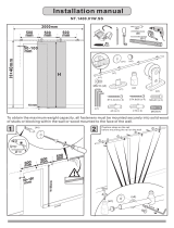
4
Thread two 1/4-20 hex thin nylon-insert locknuts (not included) on two 1/4-20 threaded rods (not
included) to the desired height of projector mount assembly. Attach projector mount assembly
(A) to the two 1/4-20 threaded rods using two 1/4-20 hex thin nylon-insert locknuts as shown in
fi gure 4.1 or fi gure 4.2.
Installation to Threaded Rod
(Not evaluated by UL - Professional installation only)
1/4-20 THREADED
ROD (NOT
INCLUDED)
1/4-20
THREADED
ROD (NOT
INCLUDED)
A
A
1/4-20 HEX THIN
NYLON-INSERT
LOCKNUT (NOT
INCLUDED)
1/4-20 HEX
THIN NYLON-
INSERT
LOCKNUT (NOT
INCLUDED)
1/4-20 HEX
THIN NYLON-
INSERT
LOCKNUT
(NOT
INCLUDED)
1/4-20 HEX THIN
NYLON-INSERT
LOCKNUT (NOT
INCLUDED)
ARROW
INDICATES
FRONT OF
MOUNT
ARROW
INDICATES
FRONT OF
MOUNT
fi g. 4.1
fi g. 4.2

9 of 51
ISSUED: 09-30-09 SHEET #: 056-9024-5 07-18-11
NOTE: The projector you are installing may differ in appearance from the sample illustrated
below.
Place projector upside down. Locate adapter plate (B) with notch facing forward as close to
projector center of gravity as possible without covering any mounting holes. Loosen channels
with 4mm security allen wrench (I), and if there are only three mounting holes remove fourth
channel. Using one channel for each mounting hole, position feet of channels over mounting
holes as shown below. IMPORTANT: If projector does not have at least three mounting holes,
do not use this adapter plate.
NOTE: Some projectors have feet which can be removed and the corresponding threaded insert
can be used for a mounting hole.
NOTE: Once channels are in position retighten fasteners.
*Notch indicates front of projector.
5
Attaching Adapter Plate to Projector
GENERIC PROJECTOR
*
MOUNTING HOLE
CHANNEL
B
FOOT OF
CHANNEL

10 of 51
ISSUED: 09-30-09 SHEET #: 056-9024-5 07-18-11
Attach adapter plate (B) to projector using one screw (J, K, L or M) for each channel as shown
below. Tighten all screws, while keeping the center of gravity. Be sure that adapter plate (B) is
straight. Adjust the feet of the channels to keep the adapter plate level. Tighten all screws with
4mm security allen wrench (I) while keeping the center of gravity. If M3 screws (J) are used,
tighten using 2mm security allen wrench (H).
NOTE: Projectors will require different size screws for mounting. Use a combination of screws
(J, K, L or M) and foot adjustment that will result in channels of adapter plate (B) fi tting tightly
against projector. IMPORTANT: In order to properly engage the threads in the mounting holes,
the screw must be turned at least 3 full turns.
NOTE: If using screw (J), place washer (G) between screw (J) and foot of channel.
6
FOOT OF
CHANNEL
J, K, L or M
B
• It is the responsibility of the installer to ensure
that the projector is properly ventilated. Feet
of channels are used to raise the mount off the
projector surface.
CAUTION

11 of 51
ISSUED: 09-30-09 SHEET #: 056-9024-5 07-18-11
7
8
• Always use an assistant or mechanical lifting equipment to safely lift and position the projector.
WARNING
Slide connection block with projector into projector mount assembly (A) as shown. Push in and
tighten captive screw to secure projector to projector mount assembly (A).
IMPORTANT: For security installations, insert one #10-32 x 1/4" socket pin screw (E) through
projector mount assembly (A) and into connection block as shown. Tighten screw with 4mm
security allen wrench (I).
CONNECTION BLOCK
A
FRONT OF MOUNT
ARROW INDICATES
FRONT OF MOUNT
CAPTIVE SCREW
CONNECTION
BLOCK
A
E

12 of 51
ISSUED: 09-30-09 SHEET #: 056-9024-5 07-18-11
Cable Management
To make an opening to route cables through
projector mount assembly, adjust projector
mount assembly to full upward tilt position
by turning knob for tilt adjustment as shown
in fi gure 9.2. Left or right roll position can be
adjusted if more space is required.
NOTE: Be certain tamper resistant
screws are not engaged before making
adjustments (see step 11).
Route cables through top of extension
column as shown in fi gure 9.1 and fi gure
9.2.
NOTE: A method for assisting cables
through extension column may be required
(example: string tied to connector to help
pull through extension column).
Route cables through projector mount
assembly as shown in fi gure 9.2 and
connect to projector.
9
DO NOT CRIMP
WIRES
BEND WIRES OF RCA
PLUGS IN OPPOSITE
DIRECTION
NOTE: INNER
DIAMETER OF
EXTENSION COLUMN
MAY NOT ALLOW
PASSAGE FOR ALL
CONNECTOR TYPES.
ROUTE
CONNECTOR
THROUGH
FIRST
CABLES WITH
COMBINATION OF VGA
CONNECTOR
AND RCA PLUGS
INNER DIAMETER
OF EXTENSION
COLUMN
CABLE
CONNECTOR
EXTENSION
COLUMN
KNOB FOR TILT
ADJUSTMENT
KNOB FOR ROLL
ADJUSTMENT
fi g. 9.2
fi g. 9.1
OPENING FOR
ROUTING CABLES

13 of 51
ISSUED: 09-30-09 SHEET #: 056-9024-5 07-18-11
To adjust yaw (swivel) for threaded rod mounting applications: Loosen locknuts for
threaded rods (step 4) until projector mount can be rotated. Rotate mount to desired position
and retighten locknuts.
To adjust yaw (swivel) for extension column applications: Loosen screw on projector mount
assembly (A) indicated below until projector mount can be rotated. Rotate mount to desired
position and retighten screw.
To adjust pitch (forward and backward tilt): Turn knob on back of mount as shown below.
Pull knob out and turn by hand for easy adjustment or insert #2 phillips screwdriver in end of
knob and turn.
To adjust roll (side to side tilt): Turn knob on side of mount as shown below. Pull knob out and
turn by hand for easy adjustment or insert #2 phillips screwdriver in end of knob and turn.
10
Projector Alignment
SCREW FOR YAW (SWIVEL) STOP
(REFER TO STEP 1, FIG. 1.2)
A
KNOB FOR ROLL
ADJUSTMENT
KNOB FOR PITCH
ADJUSTMENT
ACCESS SLOT FOR
OPEN END WRENCH
ALLOWS TIGHTENING
OF LOCKNUTS WITHOUT
REMOVING PROJECTOR
ARROW INDICATES FRONT OF
MOUNT

14 of 51
ISSUED: 09-30-09 SHEET #: 056-9024-5 07-18-11
11
To prevent tampering with the pitch and roll adjustments: Tighten the two tamper resistant
security screws on the projector mount assembly using 4mm security allen wrench (I) to lock the
pitch and roll adjustments as shown below.
NOTE: Tighten screws fi rmly, but do not overtighten. Overtightening can damage the mount.
• Do not adjust pitch or roll while tamper resistant security screws are fully engaged.
• Loosen the two tamper resistant security screws one complete turn before adjusting the projector
mount assembly or damage may occur.
WARNING
TO LOCK ROLL, TIGHTEN
TAMPER RESISTANT SECURITY
SCREW
TO LOCK PITCH, TIGHTEN
TAMPER RESISTANT
SECURITY SCREW
FRONT VIEW
SIDE VIEW

15 of 51
ISSUED: 09-30-09 SHEET #: 056-9024-5 07-18-11
PRG Series Projector Mount Accessories
I-Beam Clamps
M
ODELS
:
ACC 558, ACC 559
M
AX
L
OAD
:
250 lbs. (113.4 kg.)
C
OLOR
:
Black
• ACC 558 clamps onto 4"-8" I-Beam
• ACC 559 clamps onto 7"-12" I-Beam
Unistrut
®
Adapter
M
ODEL
:
ACC 550
M
AX
L
OAD
:
250 lbs. (113.4 kg.)
C
OLOR
:
Black
• Designed for use with
1 5/8" x 1 5/8" 12 gauge Unistrut
Accessory Pack for CMJ 455
M
ODEL
:
ACC 455*
This pack includes 4 hanger brackets and
4 hanger clamps for additional stability. For
use with model CMJ 455.
Truss Ceiling Adapter
M
ODEL
:
ACC 557*
M
AX
L
OAD
:
250 lbs. (113.4 kg.)
C
OLOR
:
Black
• Attaches to a square, round,
rectangular, or I-Beam truss up to 3" in
diameter
Escutcheon Ring
M
ODEL
:
ACC 640
• Covers hole where extension
column passes through ceiling
• Hinged ring wraps around extension column
• Included with CMJ 500
Lightweight Cathedral
Ceiling Plate
M
ODEL
:
ACC 912*
M
AX
L
OAD
:
60 lbs. (27.2 kg.)
C
OLOR
:
Black
• Designed specifically for projectors
• Allows a projector to be mounted
on an angled ceiling
New!
Lightweight Adjustable
Suspended Ceiling Kit
M
ODEL
:
CMJ 500
M
AX
L
OAD
:
60 lbs. (27.2 kg.)
C
OLOR
:
White
• Mounts above 2’ x 4’ or 2’ x 2’ false
ceiling tile
• Includes tie wire supports, flush mount
tube, and offers two knockout panels
for outlet boxes
• Offers unlimited adjustment for
projector placement
New!
Lightweight Suspended Ceiling Kit
M
ODEL
:
CMJ 455
M
AX
L
OAD
:
50 lbs. (22.7 kg.)
C
OLOR
:
White
• Five different projector
mount attachment points
• Includes tie wire supports,
flush mount tube, and
offers two knockout panels
for outlet boxes
• May either replace a 2’ x 2’ false
ceiling tile or mount above an existing
2’ x 2’ or 2’ x 4’ ceiling tile
Anti-Vibration Ceiling Plates
M
ODELS
:
ACC 840*, ACC 845*
M
AX
L
OAD
:
60 lbs. (27.2 kg.)
C
OLOR
:
Black
• ACC 840 was designed for
a structural ceiling (wood only)
• ACC 845 was designed for
a Unistrut ceiling (1 5/8" x 1 5/8"
12 gauge Unistrut)
• Reduces unwanted vibrations
that may cause internal damage
to the equipment and/or cause the
screen image to vibrate
• Features two cord management
access holes
• Patent pending
Unistrut or Structural
Ceiling Plates
M
ODELS
:
CMJ 300*, CMJ 310*
M
AX
L
OAD
:
250 lbs. (113.4 kg.)
C
OLOR
:
Black
• CMJ 300 is a 4" x 4" ceiling plate
• CMJ 310 is a 8" x 8" ceiling plate
• Designed for a Unistrut ceiling
(1 5/8" x 1 5/8" 12 gauge Unistrut)
or a solid structural ceiling
(mounting hardware not included)
Unistrut
Ceiling plate
R
R
R
Ceiling Plates
R
*
= Not UL Listed
Round Ceiling Plate
M
ODEL
:
ACC570(S)(W)
C
OLOR
:
Black, silver or white
M
AX
L
OAD
:
150 lb (68 kg)
S
HIP
W
EIGHT
:
1.7 lb (.8 kg)
• Designed for finished or
structural ceilings (wood or
concrete)
• Features a cord management
R

16 of 51
ISSUED: 09-30-09 SHEET #: 056-9024-5 07-18-11
PRG Series Projector Mount Accessories
ALLIGATOR
®
Concrete Anchors
M
ODELS
:
ACC 203, 204
• ACC 203 contains 3 anchors
• ACC 204 contains 4 anchors
• Used for attachment to
concrete, concrete block,
or brick
• Used in conjunction with wood
screws (supplied with
projector mount and/or
ceiling plate)
• Expands in length and binds to
the contours of the hole and
the screw
Cord Wrap
M
ODELS
:
ACC 852(W)(S)*
C
OLOR
:
Black, White, or Silver
Side-To-Side Adjuster
M
ODEL
:
ACC 830*
C
OLOR
:
Black
• Provides 4" of radial
adjustment side to side
• Includes Flush Mount
Tube, EXT 002
Armor Lock
TM
Plus Security Cables
M
ODEL
:
ACC 021*
• With 1/4" security cable and fasteners
• Includes adhesive for non-fastener applica
tions
M
ODEL
:
ACC 020*
• With security lock
• For use with projectors that have a built-in
security slot
Extension
column
Extension Columns
Security Accessories
Additional Projector
Mount Accessories
Cord Management
Fixed Length 1 1/2"
Extension Columns
C
OLOR
:
Black
R
C
OLOR
:
Black
Adjustable Length 1 1/2"
Extension Columns
MODEL Drop Length Ship Weight
ADJ 006009 8"-11" 4 lbs.
(1.81 kg)
ADJ 012018 14"-20" 4.75 lbs.
(2.15 kg)
ADJ 018024 20"-26" 6.25 lbs.
(2.83 kg)
ADJ 0203 26"-38" 8 lbs.
(3.63 kg)
ADJ 0305 38"-62" 13.5 lbs.
(6.12 kg)
ADJ 0406 50"-74" 16.25 lbs.
(7.37 kg)
ADJ 0507 62"-86" 18.5 lbs.
(8.39 kg)
ADJ 0608 74"-98" 21.75 lbs.
(9.87 kg)
ADJ 0709 86"-110" 24.5 lbs.
(11.11 kg)
ADJ 0810 98"-122" 27 lbs.
(12.25 kg)
ADJ 0911 110"-134" 29 lbs.
(13.15 kg)
ADJ 1012 122"-146" 31 lbs.
(14.06 kg)
R
R
*
= Not UL Listed
• Includes, four, 2' sections
• Designed to externally route cords along the
outside of an 1/2" extension column
• Sections can be stacked to create longer lengths
or cut to desired length
Extension Column
Stabilizer Kit
M
ODEL
:
ACC 050*
C
OLOR
:
Black
• Can be used to reduce
unwanted swaying that may
occur with extension
column installations
• Includes a hose clamp, two
stabilizer column supports,
& hardware for mounting to
wood joists
• For use with extension
columns over 21"
MODEL Drop Length Ship Weight
EXT 006 8"
(20 cm)
2.5 lbs
(1.13 kg)
EXT 018 20"
(51 cm)
5 lbs
(2.27 kg)
EXT 101 14"
(36 cm)
3.5 lbs
(1.59 kg)
EXT 102 26"
(66 cm)
6 lbs
(2.72 kg)
EXT 103 38"
(97 cm)
9.25 lbs
(4.2 kg)
EXT 104 50"
(127cm)
12 lbs
(5.44 kg)
EXT 105 62"
(158 cm)
14.75 lbs
(6.69 kg)
EXT 106 74"
(188 cm)
18 lbs
(8.16 kg)
EXT 107 86"
(219 cm)
20.75 lbs
(9.41 kg)
EXT 108 98"
(249 cm)
23.25 lbs
(10.55 kg)
EXT 109 110"
(279 cm)
26.5 lbs
(12.02 kg)
EXT 110 122"
(310 cm)
29 lbs
(13.15 kg)
Side to side
adjuster
Extension Column
Connector
M
ODEL
:
ACC 109*
C
OLOR
:
Black
• Can be used to join two
1-1/2" extension columns to
create a maximum length
of 20’
• Secures to columns with
Armor Lock
TM
Security
screws
Extension Column Connector
with Cord Management
M
ODEL
: ACC800, ACC850(S)
C
OLOR
: ACC800
Black
ACC850
Black or Silver
• 1-1/2" access hole for internal cord
management
• Unit has 1-1/2"-11.5 NPT fitting for
attachment of extension column
• Security screws included
• ACC800: One male and one female
connection to provide internal cord
management between extension
column and mount or ceiling plate
• ACC850: Two female connectors to
join two extension columns to
create maximum length of 20’
ACC850
ACC800

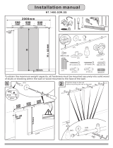
40 sur 51 PUBLIÉ LE: 09-30-09 FEUILLE No: 056-9024-5 07-18-11
Français
4
Faites passer deux écrous de blocage hexagonaux avec insert en nylon 1/4-20 (non compris)
sur deux fi xations fi letées (non comprises) à la hauteur souhaitée du support de projecteur.
Fixez le support de projecteur (A) aux deux fi xations fi letées de 1/4-20 à l’aide de deux écrous
de blocage hexagonaux avec insert en nylon 1/4-20 comme illustré à la fi gure 4.1 ou à la fi gure
4.2.
Installation à des fi xations fi letées
(Non évalué par l’UL – Installation professionnelle uniquement)
FIXATION FILETÉE
1/4-20 (NON
COMPRISE)
FIXATION
FILETÉE
1/4-20 (NON
COMPRISE)
A
A
ÉCROU DE
BLOCAGE AVEC
INSERT EN
NYLON 1/4-20
(NON
COMPRIS)
ÉCROU DE BLOCAGE
AVEC INSERT EN
NYLON 1/4-20
(NON COMPRIS)
ÉCROU DE
BLOCAGE AVEC
INSERT EN
NYLON 1/4-20
(NON COMPRIS)
ÉCROU DE
BLOCAGE AVEC
INSERT EN
NYLON 1/4-20
(NON COMPRIS)
LA FLÈCHE
INDIQUE
L’AVANT DU
SUPPORT
LA FLÈCHE
INDIQUE
L’AVANT DU
SUPPORT
fi g. 4.1
fi g. 4.2

49 of 51
ISSUED: 09-30-09 SHEET #: 056-9024-5 07-18-11
© 2011 Peerless Industries, Inc.
Peerless Industries, Inc. (“Peerless”) warrants to original end-users of Peerless® products will be free from defects in material and workmanship, under normal
use, for a period of fi ve years from the date of purchase by the original end-user (but in no case longer than six years after the date of the product’s manufacture).
At its option, Peerless will repair or replace, or refund the purchase price of, any product which fails to conform with this warranty.
In no event shall the duration of any implied warranty of merchantability or fi tness for a particular purpose be longer than the period of the applicable
express warranty set forth above. Some states do not allow limitations on how long an implied warranty lasts, so the above limitation may not apply to you.
This warranty does not cover damage caused by (a) service or repairs by the customer or a person who is not authorized for such service or repairs by Peerless,
(b) the failure to utilize proper packing when returning the product, (c) incorrect installation or the failure to follow Peerless’ instructions or warnings when installing,
using or storing the product, or (d) misuse or accident, in transit or otherwise, including in cases of third party actions and force majeure.
In no event shall Peerless be liable for incidental or consequential damages or damages arising from the theft of any product, whether or not secured
by a security device which may be included with the Peerless® product. Some states do not allow the exclusion or limitation of incidental or consequential
damages, so the above limitation or exclusion may not apply to you.
This warranty is in lieu of all other warranties, expressed or implied, and is the sole remedy with respect to product defects. No dealer, distributor, installer or other
person is authorized to modify or extend this Limited Warranty or impose any obligation on Peerless in connection with the sale of any Peerless® product.
This warranty gives specifi c legal rights, and you may also have other rights which vary from state to state.
LIMITED FIVE-YEAR WARRANTY
www.peerlessmounts.com
/