
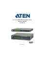
4 x 4 / 9 x 9 HDMI HDBaseT-Lite Matrix Switch
VM3404H / VM3909H
User Manual
www.aten.com

VM3404H / VM3909H User Manual
ii
EMC Information
FEDERAL COMMUNICATIONS COMMISSION INTERFERENCE STATEMENT:
This equipment has been tested and found to comply with the limits for a Class A digital
device, pursuant to Part 15 of the FCC Rules. These limits are designed to provide
reasonable protection against harmful interference when the equipment is operated in a
commercial environment. This equipment generates, uses, and can radiate radio
frequency energy and, if not installed and used in accordance with the instruction
manual, may cause harmful interference to radio communications. Operation of this
equipment in a residential area is likely to cause harmful interference in which case the
user will be required to correct the interference at his own expense.
The device complies with Part 15 of the FCC Rules. Operation is subject to the
following two conditions: (1) this device may not cause harmful interference, and (2)
this device must accept any interference received, including interference that may cause
undesired operation.
FCC Caution: Any changes or modifications not expressly approved by the party
responsible for compliance could void the user's authority to operate this equipment.
Warning: Operation of this equipment in a residential environment could cause radio
interference.
Achtung: Der Gebrauch dieses Geräts in Wohnumgebung kann Funkstörungen
verursachen.
KCC Statement
:
RoHS
This product is RoHS compliant.
© Copyright 2021 ATEN® International Co., Ltd.
Manual Date: 2021-01-06
ATEN and the ATEN logo are registered trademarks of ATEN International Co., Ltd. All rights reserved.
All other brand names and trademarks are the registered property of their respective owners. The
terms HDMI, HDMI High-Definition Multimedia Interface, and the HDMI Logo are trademarks or
registered trademarks of HDMI Licensing Administrator, Inc.

VM3404H / VM3909H User Manual
iii
User Information
Online Registration
Be sure to register your product at our online support center:
Telephone Support
For telephone support, call this number:
User Notice
All information, documentation, and specifications contained in this manual
are subject to change without prior notification by the manufacturer. The
manufacturer makes no representations or warranties, either expressed or
implied, with respect to the contents hereof and specifically disclaims any
warranties as to merchantability or fitness for any particular purpose. Any of
the manufacturer's software described in this manual is sold or licensed as is.
Should the programs prove defective following their purchase, the buyer (and
not the manufacturer, its distributor, or its dealer), assumes the entire cost of all
necessary servicing, repair and any incidental or consequential damages
resulting from any defect in the software.
The manufacturer of this system is not responsible for any radio and/or TV
interference caused by unauthorized modifications to this device. It is the
responsibility of the user to correct such interference.
The manufacturer is not responsible for any damage incurred in the operation
of this system if the correct operational voltage setting was not selected prior
to operation. PLEASE VERIFY THAT THE VOLTAGE SETTING IS
CORRECT BEFORE USE.
International http://eservice.aten.com
International 886-2-8692-6959
China 86-400-810-0-810
Japan 81-3-5615-5811
Korea 82-2-467-6789
North America 1-888-999-ATEN ext 4988
1-949-428-1111

VM3404H / VM3909H User Manual
iv
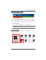
Package Contents
The VM3404H / VM3909H package consists of:
1 VM3404H / VM3909H 4 x 4 / 9 x 9 HDMI HDBaseT-Lite Matrix
Switch
1 Power Cord
1 Mounting Kit
1 User Instructions*
Check to make sure that all the components are present and that nothing got
damaged in shipping. If you encounter a problem, contact your dealer.
Read this manual thoroughly and follow the installation and operation
procedures carefully to prevent any damage to the unit, and/or any of the
devices connected to it.
* Features may have been added to the VM3404H / VM3909H since this
manual was published. Please visit our website to download the most up-to-
date version.

VM3404H / VM3909H User Manual
v
Table of Contents
EMC Information . . . . . . . . . . . . . . . . . . . . . . . . . . . . . . . . . . . . . . . . . . . . ii
RoHS. . . . . . . . . . . . . . . . . . . . . . . . . . . . . . . . . . . . . . . . . . . . . . . . . . . . . . ii
User Information . . . . . . . . . . . . . . . . . . . . . . . . . . . . . . . . . . . . . . . . . . . . .iii
Online Registration . . . . . . . . . . . . . . . . . . . . . . . . . . . . . . . . . . . . . . . .iii
Telephone Support . . . . . . . . . . . . . . . . . . . . . . . . . . . . . . . . . . . . . . . .iii
User Notice . . . . . . . . . . . . . . . . . . . . . . . . . . . . . . . . . . . . . . . . . . . . . .iii
Package Contents . . . . . . . . . . . . . . . . . . . . . . . . . . . . . . . . . . . . . . . . . . iv
Table of Contents . . . . . . . . . . . . . . . . . . . . . . . . . . . . . . . . . . . . . . . . . . . . v
About this Manual . . . . . . . . . . . . . . . . . . . . . . . . . . . . . . . . . . . . . . . . . . ix
Conventions . . . . . . . . . . . . . . . . . . . . . . . . . . . . . . . . . . . . . . . . . . . . . . . . x
Product Information. . . . . . . . . . . . . . . . . . . . . . . . . . . . . . . . . . . . . . . . . . . x
1. Introduction
Overview . . . . . . . . . . . . . . . . . . . . . . . . . . . . . . . . . . . . . . . . . . . . . . . . . . . 1
Features . . . . . . . . . . . . . . . . . . . . . . . . . . . . . . . . . . . . . . . . . . . . . . . . . . . 3
Requirements . . . . . . . . . . . . . . . . . . . . . . . . . . . . . . . . . . . . . . . . . . . . . . . 5
Source Devices . . . . . . . . . . . . . . . . . . . . . . . . . . . . . . . . . . . . . . . . . . .5
Display Devices. . . . . . . . . . . . . . . . . . . . . . . . . . . . . . . . . . . . . . . . . . . 5
Cables . . . . . . . . . . . . . . . . . . . . . . . . . . . . . . . . . . . . . . . . . . . . . . . . . . 5
Source Device Operating Systems . . . . . . . . . . . . . . . . . . . . . . . . . . . 6
Browsers . . . . . . . . . . . . . . . . . . . . . . . . . . . . . . . . . . . . . . . . . . . . . . . . 6
Components . . . . . . . . . . . . . . . . . . . . . . . . . . . . . . . . . . . . . . . . . . . . . . . . 7
VM3404H Front View . . . . . . . . . . . . . . . . . . . . . . . . . . . . . . . . . . . . . . 7
VM3404H Rear View . . . . . . . . . . . . . . . . . . . . . . . . . . . . . . . . . . . . . . 8
VM3909H Front View . . . . . . . . . . . . . . . . . . . . . . . . . . . . . . . . . . . . . . 9
VM3909H Rear View . . . . . . . . . . . . . . . . . . . . . . . . . . . . . . . . . . . . . 10
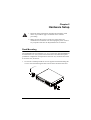
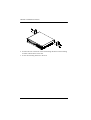
2. Hardware Setup
Rack Mounting . . . . . . . . . . . . . . . . . . . . . . . . . . . . . . . . . . . . . . . . . . . . . 11
Grounding . . . . . . . . . . . . . . . . . . . . . . . . . . . . . . . . . . . . . . . . . . . . . . . . 13
Cable Connection . . . . . . . . . . . . . . . . . . . . . . . . . . . . . . . . . . . . . . . . . . . 14
Installation Diagram . . . . . . . . . . . . . . . . . . . . . . . . . . . . . . . . . . . . . . 15
3. Front Panel Configuration
Overview . . . . . . . . . . . . . . . . . . . . . . . . . . . . . . . . . . . . . . . . . . . . . . . . . . 17
Front Panel Pushbuttons. . . . . . . . . . . . . . . . . . . . . . . . . . . . . . . . . . . . . . 17
Enter Password . . . . . . . . . . . . . . . . . . . . . . . . . . . . . . . . . . . . . . . . . . . .18
Main Screen . . . . . . . . . . . . . . . . . . . . . . . . . . . . . . . . . . . . . . . . . . . . . . . 19
Port Switching . . . . . . . . . . . . . . . . . . . . . . . . . . . . . . . . . . . . . . . . . . 19
Input Port Selection . . . . . . . . . . . . . . . . . . . . . . . . . . . . . . . . . . . . 19
Output Port Selection. . . . . . . . . . . . . . . . . . . . . . . . . . . . . . . . . . . 21
LCD Menu Organization . . . . . . . . . . . . . . . . . . . . . . . . . . . . . . . . . . . . . . 23
Menu Pushbutton . . . . . . . . . . . . . . . . . . . . . . . . . . . . . . . . . . . . . . . . . . . 23

VM3404H / VM3909H User Manual
vi
IP Setting. . . . . . . . . . . . . . . . . . . . . . . . . . . . . . . . . . . . . . . . . . . . . . . 24
IP Address / Subnet Mask. . . . . . . . . . . . . . . . . . . . . . . . . . . . . . . 24
Gateway . . . . . . . . . . . . . . . . . . . . . . . . . . . . . . . . . . . . . . . . . . . . 24
Serial Port Setting . . . . . . . . . . . . . . . . . . . . . . . . . . . . . . . . . . . . . . . 26
Baud Rate . . . . . . . . . . . . . . . . . . . . . . . . . . . . . . . . . . . . . . . . . . . 26
Operation Mode . . . . . . . . . . . . . . . . . . . . . . . . . . . . . . . . . . . . . . . . . 27
EDID Mode . . . . . . . . . . . . . . . . . . . . . . . . . . . . . . . . . . . . . . . . . . 27
CEC. . . . . . . . . . . . . . . . . . . . . . . . . . . . . . . . . . . . . . . . . . . . . . . . 28
OSD. . . . . . . . . . . . . . . . . . . . . . . . . . . . . . . . . . . . . . . . . . . . . . . . 29
Output Status . . . . . . . . . . . . . . . . . . . . . . . . . . . . . . . . . . . . . . . . 30
Security Mode . . . . . . . . . . . . . . . . . . . . . . . . . . . . . . . . . . . . . . . . . . 32
Mode . . . . . . . . . . . . . . . . . . . . . . . . . . . . . . . . . . . . . . . . . . . . . . . 32
Change Password . . . . . . . . . . . . . . . . . . . . . . . . . . . . . . . . . . . . . 33
Save to a Profile . . . . . . . . . . . . . . . . . . . . . . . . . . . . . . . . . . . . . . . . . 35
Play/Stop the Profile Schedule . . . . . . . . . . . . . . . . . . . . . . . . . . . . . . 36
Turn Video Wall Off. . . . . . . . . . . . . . . . . . . . . . . . . . . . . . . . . . . . . . . 36
Profile Pushbutton . . . . . . . . . . . . . . . . . . . . . . . . . . . . . . . . . . . . . . . . . . 37
4. Browser Operation
Overview. . . . . . . . . . . . . . . . . . . . . . . . . . . . . . . . . . . . . . . . . . . . . . . . . . 39
Logging In . . . . . . . . . . . . . . . . . . . . . . . . . . . . . . . . . . . . . . . . . . . . . . . . . 39
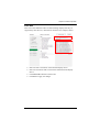
Main Page . . . . . . . . . . . . . . . . . . . . . . . . . . . . . . . . . . . . . . . . . . . . . . . . 40
Menu Bar . . . . . . . . . . . . . . . . . . . . . . . . . . . . . . . . . . . . . . . . . . . . . . 40
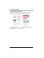
Profile List . . . . . . . . . . . . . . . . . . . . . . . . . . . . . . . . . . . . . . . . . . . . . . . . 41
Adding/Playing a Profile . . . . . . . . . . . . . . . . . . . . . . . . . . . . . . . . . . . 41
Importing / Exporting a Profile . . . . . . . . . . . . . . . . . . . . . . . . . . . . . . 43
Profile List Options . . . . . . . . . . . . . . . . . . . . . . . . . . . . . . . . . . . . . . . 43
Profile . . . . . . . . . . . . . . . . . . . . . . . . . . . . . . . . . . . . . . . . . . . . . . 44
Play Window . . . . . . . . . . . . . . . . . . . . . . . . . . . . . . . . . . . . . . . . . 44
Profile Scheduling . . . . . . . . . . . . . . . . . . . . . . . . . . . . . . . . . . . . . . . . . . 46
Connection Profiles . . . . . . . . . . . . . . . . . . . . . . . . . . . . . . . . . . . . . . . . . 48
Digital Signage Profile. . . . . . . . . . . . . . . . . . . . . . . . . . . . . . . . . . . . . 48
Output Icon . . . . . . . . . . . . . . . . . . . . . . . . . . . . . . . . . . . . . . . . . . 49
Grid View. . . . . . . . . . . . . . . . . . . . . . . . . . . . . . . . . . . . . . . . . . . . 50
Output Options . . . . . . . . . . . . . . . . . . . . . . . . . . . . . . . . . . . . . . . 50
Video Wall Profile . . . . . . . . . . . . . . . . . . . . . . . . . . . . . . . . . . . . . . . . 51
Video Wall Options . . . . . . . . . . . . . . . . . . . . . . . . . . . . . . . . . . . . 51
Number of Displays / Output Order / Bezel Dimensions . . . . . . . . 52
Null Input . . . . . . . . . . . . . . . . . . . . . . . . . . . . . . . . . . . . . . . . . . . 53
Independent Output. . . . . . . . . . . . . . . . . . . . . . . . . . . . . . . . . . . . 53
Group . . . . . . . . . . . . . . . . . . . . . . . . . . . . . . . . . . . . . . . . . . . . . . 54
Display Preferences . . . . . . . . . . . . . . . . . . . . . . . . . . . . . . . . . . . 55
Video Wall Example 1 . . . . . . . . . . . . . . . . . . . . . . . . . . . . . . . . . . 56
Video Wall Example 2 . . . . . . . . . . . . . . . . . . . . . . . . . . . . . . . . . . 56
Output Option . . . . . . . . . . . . . . . . . . . . . . . . . . . . . . . . . . . . . . . . . . . . . 58
Video Control’s . . . . . . . . . . . . . . . . . . . . . . . . . . . . . . . . . . . . . . . . . . 58

VM3404H / VM3909H User Manual
vii
System Settings . . . . . . . . . . . . . . . . . . . . . . . . . . . . . . . . . . . . . . . . . . . . 59
General . . . . . . . . . . . . . . . . . . . . . . . . . . . . . . . . . . . . . . . . . . . . . . . . 60
Fan Status . . . . . . . . . . . . . . . . . . . . . . . . . . . . . . . . . . . . . . . . . . . 60
Device Info. . . . . . . . . . . . . . . . . . . . . . . . . . . . . . . . . . . . . . . . . . . 60
Other . . . . . . . . . . . . . . . . . . . . . . . . . . . . . . . . . . . . . . . . . . . . . . . 60
User Account . . . . . . . . . . . . . . . . . . . . . . . . . . . . . . . . . . . . . . . . . . . . . . 62
Add Account . . . . . . . . . . . . . . . . . . . . . . . . . . . . . . . . . . . . . . . . . . . . 63
Permission Level . . . . . . . . . . . . . . . . . . . . . . . . . . . . . . . . . . . . . . . . 64
Port Name . . . . . . . . . . . . . . . . . . . . . . . . . . . . . . . . . . . . . . . . . . . . . 65
Network . . . . . . . . . . . . . . . . . . . . . . . . . . . . . . . . . . . . . . . . . . . . . . . 66
EDID Settings . . . . . . . . . . . . . . . . . . . . . . . . . . . . . . . . . . . . . . . . . . . 67
EDID Mode . . . . . . . . . . . . . . . . . . . . . . . . . . . . . . . . . . . . . . . . . . 68
EDID & CEA Description . . . . . . . . . . . . . . . . . . . . . . . . . . . . . . . .69
Customized Mode . . . . . . . . . . . . . . . . . . . . . . . . . . . . . . . . . . . . . 70
Customized EDID Parameters. . . . . . . . . . . . . . . . . . . . . . . . . . . .71
CEA Settings . . . . . . . . . . . . . . . . . . . . . . . . . . . . . . . . . . . . . . . . . 74
Video Data . . . . . . . . . . . . . . . . . . . . . . . . . . . . . . . . . . . . . . . . . . . 75
Detail Timing / Display Description . . . . . . . . . . . . . . . . . . . . . . . . 76
Maintenance . . . . . . . . . . . . . . . . . . . . . . . . . . . . . . . . . . . . . . . . . . . . 77
IR Channel . . . . . . . . . . . . . . . . . . . . . . . . . . . . . . . . . . . . . . . . . . . . . 78
HDCP . . . . . . . . . . . . . . . . . . . . . . . . . . . . . . . . . . . . . . . . . . . . . . . . . 79
OSD/CEC . . . . . . . . . . . . . . . . . . . . . . . . . . . . . . . . . . . . . . . . . . . . . . 80
5. Mobile Control
Overview . . . . . . . . . . . . . . . . . . . . . . . . . . . . . . . . . . . . . . . . . . . . . . . . . . 81
The Video Matrix Control App . . . . . . . . . . . . . . . . . . . . . . . . . . . . . . . . . 82
Requirements . . . . . . . . . . . . . . . . . . . . . . . . . . . . . . . . . . . . . . . . . . . 82
Installation and Connections . . . . . . . . . . . . . . . . . . . . . . . . . . . . . . . . 82
The Control Interface. . . . . . . . . . . . . . . . . . . . . . . . . . . . . . . . . . . . . . 83
6. CLI Commands
Overview . . . . . . . . . . . . . . . . . . . . . . . . . . . . . . . . . . . . . . . . . . . . . . . . . . 85
Connecting to the Matrix Switch via Telnet. . . . . . . . . . . . . . . . . . . . . . . . 85
Connecting to the Matrix Switch via RS-232 . . . . . . . . . . . . . . . . . . . . . . 86
Verification. . . . . . . . . . . . . . . . . . . . . . . . . . . . . . . . . . . . . . . . . . . . . . 86
Commands . . . . . . . . . . . . . . . . . . . . . . . . . . . . . . . . . . . . . . . . . . . . . . . . 87
Switch Port Command. . . . . . . . . . . . . . . . . . . . . . . . . . . . . . . . . . . . . 87
EDID Mode Command . . . . . . . . . . . . . . . . . . . . . . . . . . . . . . . . . . . . 89
CEC Command . . . . . . . . . . . . . . . . . . . . . . . . . . . . . . . . . . . . . . . . . 90
Scaling Command . . . . . . . . . . . . . . . . . . . . . . . . . . . . . . . . . . . . . . .91
Echo Command . . . . . . . . . . . . . . . . . . . . . . . . . . . . . . . . . . . . . . . . . 94
Read Command . . . . . . . . . . . . . . . . . . . . . . . . . . . . . . . . . . . . . . . . . 95
Reset Command . . . . . . . . . . . . . . . . . . . . . . . . . . . . . . . . . . . . . . . . 96
Baud Rate Command . . . . . . . . . . . . . . . . . . . . . . . . . . . . . . . . . . . . . 97
Save/Load Profile Command . . . . . . . . . . . . . . . . . . . . . . . . . . . . . . . 98
OSD Command . . . . . . . . . . . . . . . . . . . . . . . . . . . . . . . . . . . . . . . . . 99

VM3404H / VM3909H User Manual
viii
Appendix
Safety Instructions . . . . . . . . . . . . . . . . . . . . . . . . . . . . . . . . . . . . . . . . . 101
General . . . . . . . . . . . . . . . . . . . . . . . . . . . . . . . . . . . . . . . . . . . . . . 101
Rack Mounting . . . . . . . . . . . . . . . . . . . . . . . . . . . . . . . . . . . . . . . . . 103
Technical Support . . . . . . . . . . . . . . . . . . . . . . . . . . . . . . . . . . . . . . . . . 104
International . . . . . . . . . . . . . . . . . . . . . . . . . . . . . . . . . . . . . . . . . . . 104
North America . . . . . . . . . . . . . . . . . . . . . . . . . . . . . . . . . . . . . . . . . 104
Specifications . . . . . . . . . . . . . . . . . . . . . . . . . . . . . . . . . . . . . . . . . . . . . 105
Compatible Receivers . . . . . . . . . . . . . . . . . . . . . . . . . . . . . . . . . . . . . . 107
Telnet Operation . . . . . . . . . . . . . . . . . . . . . . . . . . . . . . . . . . . . . . . . . . 108
Configuration Menu. . . . . . . . . . . . . . . . . . . . . . . . . . . . . . . . . . . . . . 108
1. H – Call up the command list for help . . . . . . . . . . . . . . . . . . 108
2. IP – Set IP address . . . . . . . . . . . . . . . . . . . . . . . . . . . . . . . . . 108
3. LO – Load connections from profile . . . . . . . . . . . . . . . . . . . . 108
4. PW – Change password . . . . . . . . . . . . . . . . . . . . . . . . . . . . . 109
5. RI – Read what input is connected to nn output . . . . . . . . . . . 109
6. RO – Read what output is connected to nn input . . . . . . . . . . 109
7. SB – Set serial port baud rate . . . . . . . . . . . . . . . . . . . . . . . . . 109
8. SS – Switch input to specified output . . . . . . . . . . . . . . . . . . . 109
9. SV – Save the current connections into a profile . . . . . . . . . . 109
10. TI – Set timeout . . . . . . . . . . . . . . . . . . . . . . . . . . . . . . . . . . . 109
11. VR – Software version information . . . . . . . . . . . . . . . . . . . . 109
Limited Warranty. . . . . . . . . . . . . . . . . . . . . . . . . . . . . . . . . . . . . . . . . . . 110

VM3404H / VM3909H User Manual
ix
About this Manual
This User Manual is provided to help you get the most from your VM3404H /
VM3909H system. It covers all aspects of installation, configuration and
operation. An overview of the information found in the manual is provided
below.
Chapter 1 Introduction, introduces you to the VM3404H / VM3909H
system. Its purpose, features and benefits are presented, and its front and back
panel components are described.
Chapter 2 Hardware Setup, describes how to set up your VM3404H /
VM3909H installation.
Chapter 3 Front Panel Configuration, explains the fundamental
concepts involved in operating the VM3404H / VM3909H at the local site via
the front panel LCD display using pushbuttons.
Chapter 4 Browser Operation, provides a complete description of the
VM3404H / VM3909H's Browser Graphical User Interface (GUI), and how to
use it to remotely configure and operate the VM3404H / VM3909H.
Chapter 5 Mobile Control, introduces you to the Video Matrix Control app
and provides details on its installation requirements.
Chapter 6 CLI Commands, provides a complete list of the serial control
protocol commands used when utilizing the RS-232 Serial Port so that an extra
source device can be utilized in the installation.
Appendix, provides specifications and other technical information regarding
the VM3404H / VM3909H.

VM3404H / VM3909H User Manual
x
Conventions
This manual uses the following conventions:
Product Information
For information about all ATEN products and how they can help you connect
without limits, visit ATEN on the Web or contact an ATEN Authorized
Reseller. Visit ATEN on the Web for a list of locations and telephone numbers:
Monospaced Indicates text that you should key in.
[ ] Indicates keys you should press. For example, [Enter] means to
press the Enter key. If keys need to be chorded, they appear
together in the same bracket with a plus sign between them:
[Ctrl+Alt].
1. Numbered lists represent procedures with sequential steps.
♦ Bullet lists provide information, but do not involve sequential steps.
→ Indicates selecting the option (on a menu or dialog box, for
example), that comes next. For example, Start
→
Run means to
open the Start menu, and then select Run.
Indicates critical information.
International http://www.aten.com
North America http://www.aten-usa.com

1
Chapter 1
Introduction
Overview
The ATEN VanCryst VM3404H / VM3909H 4 x 4 / 9 x 9 HDMI HDBaseT-
Lite Matrix Switchis a versatile solution that provides an easy way to route
high definition video and audio from any of 4/9 HDMI sources to any of 4/9
HDMI/HDBaseT displays at the same time. As a Matrix Switch, each input can
be independently connected to any or all outputs, giving you the ultimate in
flexibility and control in any multi-display audio/video installation.
Furthermore, with the latest HDBaseT technology, the VM3404H / VM3909H
is able to extend HDMI sources up to 4K2K high-resolution video (with audio
signals) over single Cat5 cable to receivers up to 60m away. The VM3404H /
VM3909H also features Power over HDBaseT (POH), which can send power
over Cat 5e/6 cable without an additional power supply.
When the VM3404H / VM3909H is combined with VE805R/VE816R
receivers, it supports both ATEN Seamless Switch™ technology and Video
Wall functionality, employing FPGA matrix system architecture to seamlessly
switch between multiple sources and multiple displays. With EDID Expert
technology, the VM3404H / VM3909H selects the optimum EDID settings for
smooth power-up and the highest quality display. It also features a high-
performing scaling engine that converts the video resolution into the display's
native resolution to give you the best image quality.
You can easily configure the VM3404H / VM3909H via the front panel LCD
display and pushbuttons, and through the use of an IR Remote Control. The
LCD provides a quick view of all port connections, and lets operators access
the unit’s built-in configuration utility.
Furthermore, the VM3404H / VM3909H allows convenient configuration and
operation via an intuitive Graphical User Interface (GUI) using any web
browser. The web GUI provides you with advanced features which include
easy setup of custom Video Wall (when used in conjunction with VE805R/
VE816R receivers) and Digital Signage configurations that can be saved and
recalled. Because your VM3404H / VM3909H can be controlled over a
standard TCP/IP connection, it conveniently integrates into any existing
network for easy remote access. For complete system and install integration,
serial control is standard through the VM3404H / VM3909H’s built-in RS-232
port that allows the switch to be controlled through a high-end controller or PC.

VM3404H / VM3909H User Manual
2
The VM3404H / VM3909H also supports mobile control of frequently used
features such as switching of profile and AV inputs using ATEN Video Matrix
Control app.
The VM3404H / VM3909H is an ideal solution for applications that require
HDMI outputs from multiple sources to be conveniently delivered to multiple
destinations, such as for stage presentations, competitions, control centers, and
system installations that require real-time reports.

Chapter 1. Introduction
3
Features
Supports 4 (VM3404H) or 9 (VM3909H) HDMI inputs and mirrored 4 / 9
HDMI and HDBaseT outputs
Long Distance Transmission – supports up to 60 m (using Cat 5e/6 cables)
or 70m (Cat 6a)
HDMI (4K, 3D, Deep Color); HDCP 1.4 compatible
Video Wall - allows you to create custom video wall layouts via intuitive
web GUI
Note: 1. The video wall feature is only available when the VM3404H /
VM3909H is used in conjunction with the VE805R/VE816R.
2. The VE816R is only supported on VM3404H / VM3909H using
firmware version 2.2.213 or later.
Features a built in high-performance scaler function for best image quality
(Only available when the VM3404H / VM3909H is used in conjunction
with the VE805R/VE816R.)
Easily switch between multiple sources and multiple displays
Seamless Switch
TM
– provides continuous video streams, real-time
switching and stable signal transmission
Note: 1. If Seamless Switch
TM
is enabled, the video output will not display
4K, 3D, Deep Color or interlaced resolutions (i.e., 1080i). For
these features, you must disable Seamless Switch
TM
.
2. Seamless Switch
TM
is only available when the VM3404H /
VM3909H is used in conjunction with the VE805R/VE816R.
3. The VE816R is only supported on VM3404H / VM3909H using
firmware version 2.2.213 or later.
EDID Expert
TM
– selects optimum EDID settings for smooth power-up and
highest quality display
Configuration and control via the front-panel LCD display and the
pushbuttons, and web GUI
Supports free mobile control using the Video Matrix Control App
System Operation:
Serial controller

VM3404H / VM3909H User Manual
4
Browser Graphical User Interface (GUI)
Telnet
Built-in bi-directional RS-232 serial port for high-end system control
Superior video quality – HDTV resolution of 480p, 720p, 1080i, 1080p
(1920 x 1080) and 4K
Supports Dolby True HD and DTS HD Master audio
Consumer Electronics Control (CEC) support
ESD protection for HDMI connections
Firmware upgradeable
Rack mountable all metal casing

Chapter 1. Introduction
5
Requirements
The following devices are required for a complete VM3404H / VM3909H
installation:
Source Devices
Computer or A/V source device with HDMI Type A output connector(s)
Note: A DVI/HDMI adapter is required when connecting a DVI source device.
Display Devices
Display devices or receivers with an HDMI Type A input connector
Cables
1 HDMI cable for each source device you will be connecting
1 HDMI cable for each display device you will be connecting
1 Cat 5e cable
1 RS-232 serial cable
Note:
No cables are included in this package. We strongly recommend that
you purchase high-quality cables of appropriate length since this will
affect the quality of the audio and video display. Contact your dealer to
purchase the correct cable sets.

VM3404H / VM3909H User Manual
6
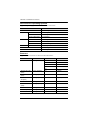
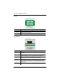
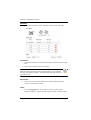
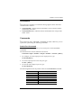
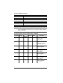
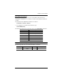
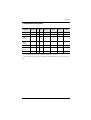
Source Device Operating Systems
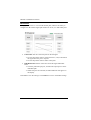
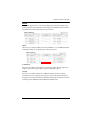
Supported operating systems are shown in the table below:
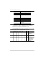
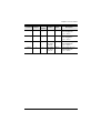
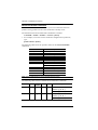
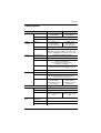
Browsers
Supported web browsers are shown in the table below:
OS Version
Windows 2000 and higher
Linux RedHat 6.0 and higher
SuSE 8.2 and higher
Mandriva (Mandrake) 9.0 and higher
UNIX AIX 4.3 and higher
FreeBSD 3.51 and higher
Sun Solaris 8 and higher
Novell Netware 5.0 and higher
Mac OS 9 and higher
DOS 6.2 and higher
OS Java Version Browser Version
Windows 8.1 V1.8.0_60 Chrome 45.0.2454.85 m
Firefox 40.0.3
Safari 5.1.7
Opera 31.0.1889.174
IE11 11
Windows 2012 R2
(64bit)
V1.8.0_60 (64bit) IE11 11 (64bit)
Windows 2008 R2
(64bit)
V1.8.0_60 (64bit) IE8 8
Windows 7
SP1(64bit)
V1.8.0_60 (64bit) IE10 10 (64bit)
Windows XP V1.8.0_60 IE8 8
CentOS 7.0
(64Bit)
V1.8.0_60 (64bit) Firefox 40.0.3
Ubuntu 12.04 V1.8.0_60 Chrome 45.0.2454.85
Solaris 11(64bit) V1.8.0_25 Firefox 33
Mac 10.10 V1.8.0_25 Safari 8

Chapter 1. Introduction
7
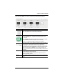
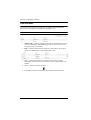
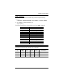
Components
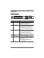
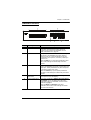
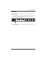
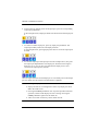
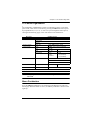
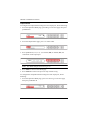
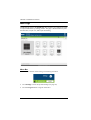
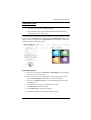
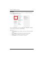
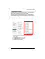
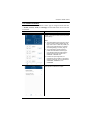
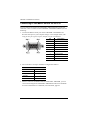
VM3404H Front View
No. Component Description
1 LCD Display The LCD Display gives a quick view of all port
connections, and shows the various options for
configuring and operating the VM3404H. For full
details, see Main Screen, page 19.
2 Input Pushbuttons These pushbuttons refer to the HDMI Input ports found
on the VM3404H rear panel. Press to select the Input
port. These pushbuttons may also correspond to menu
options, connection profiles (P1–P4) and so on.
Note: The INPUT (1–4) front panel pushbuttons have
built-in LEDs that light to indicate they have been
selected.
3 Output Pushbuttons These pushbuttons refer to the HDMI/HDBaseT
Output ports found on the VM3404H rear panel. Press
to select the Output port. These pushbuttons may also
correspond to connection profiles (P5–P8).
Note: The OUTPUT (1–4) front panel pushbuttons
have built-in LEDs that light to indicate they have been
selected.
4 Prev / Next
Pushbuttons
These pushbuttons allow you to cycle through the
menu options on the LCD display.
5 Function Pushbuttons The function pushbuttons (MENU, PROFILE, ENTER
and CANCEL) are for navigating the LCD built-in
configuration utility. For full details, see Front Panel
Pushbuttons, page 17.
Note: The MENU and PROFILE front panel
pushbuttons have built-in LEDs that light to indicate
they have been selected.
1
2
3
4 5

VM3404H / VM3909H User Manual
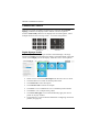
8
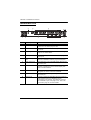
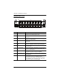
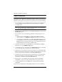
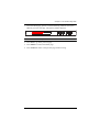
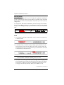
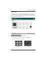
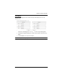
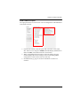
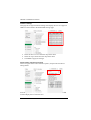
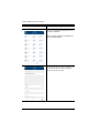
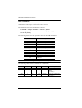
VM3404H Rear View
No. Component Description
1 Power Socket This is a standard 3-pin AC power socket. The power
cord from an AC source plugs in here.
2 Power Switch This is a standard rocker switch that powers the unit
on and off.
3 Grounding Terminal The grounding wire attaches here. See Grounding,
page 13, for further details.
4 HDMI Input Ports The cables from your HDMI source devices plug into
these ports.
5 HDBaseT Output
Ports
The cables from your remote HDBaseT display
devices or HDBaseT receivers plug into these ports.
6 HDMI Output Ports The cables from your local HDMI display devices plug
into these ports.
7 IR Channel Ports Connect IR receivers / transmitters into the IR Channel
ports for controlling the source and the display from
local or remote locations.
8 IR Port Connect an IR unit via the 3.5 mm Mini Stereo Jacks.
IR signals are used to control the VM3404H.
9 RS-232 Serial Port Connect a computer or high-end system controller via
this serial port.
10 Ethernet Port In order to access the VM3404H’s Browser Graphical
User Interface (GUI), the VM3404H must be
connected to your network. The cable that connects
the VM3404H to your LAN plugs in here. See Cable
Connection, page 14, for further details
1
2
3
4
5
7
9
10
8
6

Chapter 1. Introduction
9
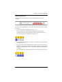
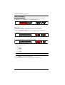
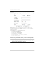
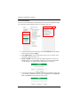
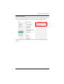
VM3909H Front View
No. Component Description
1 LCD Display The LCD Display gives a quick view of all port
connections, and shows the various options for
configuring and operating the VM3909H. For full
details, see Main Screen, page 19.
2 Input Pushbuttons These pushbuttons refer to the HDMI/HDBaseT Input
ports found on the VM3909H rear panel. Press to
select the Input port. These pushbuttons may also
correspond to menu options, connection profiles (P1–
P9) and so on.
Note: The INPUT (1–9) front panel pushbuttons have
built-in LEDs that light to indicate they have been
selected.
3 Output Pushbuttons These pushbuttons refer to the HDMI Output ports
found on the VM3909H rear panel. Press to select the
Output port. These pushbuttons may also correspond
to connection profiles (P10–P18).
Note: The OUTPUT (1–9) front panel pushbuttons
have built-in LEDs that light to indicate they have been
selected.
4 Prev / Next
Pushbuttons
These pushbuttons allow you to cycle through the
menu options on the LCD display.
5 Function Pushbuttons The function pushbuttons (MENU, PROFILE, ENTER
and CANCEL) are for navigating the LCD built-in
configuration utility. For full details, see Front Panel
Pushbuttons, page 17.
Note: The MENU and PROFILE front panel
pushbuttons have built-in LEDs that light to indicate
they have been selected.
1
2
3
4 5

VM3404H / VM3909H User Manual
10
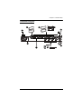
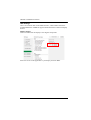
VM3909H Rear View
No. Component Description
1 Power Socket This is a standard 3-pin AC power socket. The power
cord from an AC source plugs in here.
2 Power Switch This is a standard rocker switch that powers the unit
on and off.
3 Grounding Terminal The grounding wire attaches here. See Grounding,
page 13, for further details.
4 HDMI Input Ports The cables from your HDMI source devices plug into
these ports.
5 HDBaseT Output
Ports
The cables from your remote HDBaseT display
devices or HDBaseT receivers plug into these ports.
6 HDMI Output Ports The cables from your local HDMI display devices plug
into these ports.
7 IR Channel Ports Connect IR receivers / transmitters into the IR Channel
ports for controlling the source and the display from
local or remote locations.
8 IR Port Connect an IR unit via the 3.5 mm Mini Stereo Jacks.
IR signals are used to control the VM3909H.
9 RS-232 Serial Port Connect a computer or high-end system controller via
this serial port.
10 Ethernet Port In order to access the VM3909H’s Browser Graphical
User Interface (GUI), the VM3909H must be
connected to your network. The cable that connects
the VM3909H to your LAN plugs in here. See Cable
Connection, page 14, for further details
1
2
3
10
4
5
7
9
8
6
Page is loading ...
Page is loading ...
Page is loading ...
Page is loading ...
Page is loading ...
Page is loading ...
Page is loading ...
Page is loading ...
Page is loading ...
Page is loading ...
Page is loading ...
Page is loading ...
Page is loading ...
Page is loading ...
Page is loading ...
Page is loading ...
Page is loading ...
Page is loading ...
Page is loading ...
Page is loading ...
Page is loading ...
Page is loading ...
Page is loading ...
Page is loading ...
Page is loading ...
Page is loading ...
Page is loading ...
Page is loading ...
Page is loading ...
Page is loading ...
Page is loading ...
Page is loading ...
Page is loading ...
Page is loading ...
Page is loading ...
Page is loading ...
Page is loading ...
Page is loading ...
Page is loading ...
Page is loading ...
Page is loading ...
Page is loading ...
Page is loading ...
Page is loading ...
Page is loading ...
Page is loading ...
Page is loading ...
Page is loading ...
Page is loading ...
Page is loading ...
Page is loading ...
Page is loading ...
Page is loading ...
Page is loading ...
Page is loading ...
Page is loading ...
Page is loading ...
Page is loading ...
Page is loading ...
Page is loading ...
Page is loading ...
Page is loading ...
Page is loading ...
Page is loading ...
Page is loading ...
Page is loading ...
Page is loading ...
Page is loading ...
Page is loading ...
Page is loading ...
Page is loading ...
Page is loading ...
Page is loading ...
Page is loading ...
Page is loading ...
Page is loading ...
Page is loading ...
Page is loading ...
Page is loading ...
Page is loading ...
Page is loading ...
Page is loading ...
Page is loading ...
Page is loading ...
Page is loading ...
Page is loading ...
Page is loading ...
Page is loading ...
Page is loading ...
Page is loading ...
Page is loading ...
Page is loading ...
Page is loading ...
Page is loading ...
Page is loading ...
Page is loading ...
Page is loading ...
Page is loading ...
Page is loading ...
Page is loading ...
-
 1
1
-
 2
2
-
 3
3
-
 4
4
-
 5
5
-
 6
6
-
 7
7
-
 8
8
-
 9
9
-
 10
10
-
 11
11
-
 12
12
-
 13
13
-
 14
14
-
 15
15
-
 16
16
-
 17
17
-
 18
18
-
 19
19
-
 20
20
-
 21
21
-
 22
22
-
 23
23
-
 24
24
-
 25
25
-
 26
26
-
 27
27
-
 28
28
-
 29
29
-
 30
30
-
 31
31
-
 32
32
-
 33
33
-
 34
34
-
 35
35
-
 36
36
-
 37
37
-
 38
38
-
 39
39
-
 40
40
-
 41
41
-
 42
42
-
 43
43
-
 44
44
-
 45
45
-
 46
46
-
 47
47
-
 48
48
-
 49
49
-
 50
50
-
 51
51
-
 52
52
-
 53
53
-
 54
54
-
 55
55
-
 56
56
-
 57
57
-
 58
58
-
 59
59
-
 60
60
-
 61
61
-
 62
62
-
 63
63
-
 64
64
-
 65
65
-
 66
66
-
 67
67
-
 68
68
-
 69
69
-
 70
70
-
 71
71
-
 72
72
-
 73
73
-
 74
74
-
 75
75
-
 76
76
-
 77
77
-
 78
78
-
 79
79
-
 80
80
-
 81
81
-
 82
82
-
 83
83
-
 84
84
-
 85
85
-
 86
86
-
 87
87
-
 88
88
-
 89
89
-
 90
90
-
 91
91
-
 92
92
-
 93
93
-
 94
94
-
 95
95
-
 96
96
-
 97
97
-
 98
98
-
 99
99
-
 100
100
-
 101
101
-
 102
102
-
 103
103
-
 104
104
-
 105
105
-
 106
106
-
 107
107
-
 108
108
-
 109
109
-
 110
110
-
 111
111
-
 112
112
-
 113
113
-
 114
114
-
 115
115
-
 116
116
-
 117
117
-
 118
118
-
 119
119
-
 120
120


Ask a question and I''ll find the answer in the document
Finding information in a document is now easier with AI
Related papers
Other documents
-
DirekTronik SX-VW02 User manual
-
iogear GHMS8044 Quick start guide
-
iogear GHMS8422 Quick start guide
-
Velleman VMB8PBU Owner's manual
-
birddog Play User guide
-
SIIG AV-GM08X3-S1 User manual
-
Robe Ropix P18 User manual
-
AV:Link MaitreView 4KPlus User guide
-
ATEN Technology TV Cables VS0108HA User manual
-
ITT 801P5 User manual