Page is loading ...

RVision P/N 660904-01 Rev 1
SEE™
Setup and Operations Manual
ITAR AND EAR – EXPORT REGULATION COMPLIANCE
Warning: Some of the Commodities, Products, Technologies, and Services contained in this document
may be/are subject to one or more export control laws and regulations of the United States Govern-
ment and they fall under the control jurisdiction of either the U.S. Department of State or the U.S.
Bureau of Industry and Security – U.S. Department of Commerce. It is unlawful and strictly prohibited
to export, or attempt to export or otherwise transfer or sell any hardware or technical data or furnish
any service to any foreign person, whether abroad or in the United States, for which a license or writ-
ten approval of the U.S. Government is required, without first obtaining the required license or written
approval from the appropriate Department of the U.S. Government having jurisdiction in such matters.
Diversion contrary to U.S. law is prohibited.

RVision P/N 660904-01 Rev 1
Copyright © 2004 - 2010 RVision, Inc. All rights reserved.
WARRANTY CONDITIONS
Our warranty is limited to the repair or replacement of RVision product. RVision reserves the right to decide if a repair
or replacement is warranted.
RVision does not authorize any party to assume for it any other obligation or liability.
RVision warrants that each of the component parts of the system will not malfunction, destruct or fail to operate for a
period of one (1) year when operated as described in RVision documentation and instructions packaged with the
product.
WARNING
The system enclosure is pressurized with nitrogen to keep the camera lens free of condensation. Any attempt to
remove the cover will void the warranty and might cause system damage.
Operating this system in an environment below -15°C or above +50°C can cause permanent damage and will void the
warranty.
See the back of this manual for a complete warranty, liability and copyright statement.
CAUTION
Please read this manual to avoid improper installation. Careless operation of any RVision Pan/Tilt device can result in
injury or system damage.
The SEE™ requires an input voltage of 12-30 volts direct current (VDC). Applying power out of this range may damage
the unit.
Replace the lens cap when not in use. Avoid pointing the camera directly at the sun, lasers, arc welders or other high-
intensity radiation sources; even when no power is applied to the system.
TRADEMARKS
RVision, RVisionUSA, LOOK™, SEE™, SEE™IP, PatrolCCTV™, m3G™, Dual i50™ and other trademarks are
registered trademarks of RVision, Incorporated.
QuickConnect patent is pending. Other trademarks and service marks in this document are the property of their
respective owners.
HYPERTEXT LINKING
Click on underline blue text, a listing in the Table of Contents or other text, where noted, to display another page of the
same or related topic.
TECHNICAL SUPPORT/SALES & MARKETING
techsupport@rvisionusa.com
sales@rvisionusa.com

RVision P/N 660904-01 Rev 1 iii
Contents
Introduction .............................................................................. 1
ITAR AND EAR – EXPORT REGULATION COMPLIANCE ..................... 2
About this Document .................................................................. 2
Connecting the SEE™ Camera to a PC .......................................... 3
Mounting the QuickConnect Mount/Cable to a Pole ......................... 4
Mounting the Camera ................................................................. 5
Testing the Mount .................................................................. 5
Connecting the HiDef to Adapter to the SEE2PC
Integration Tool ................................................................... 6
Using the RS422 to RS232 adapter .......................................... 7
Connecting the RS-232 connector to a PC ..................................... 7
Connecting Power to the Camera ................................................. 8
Connecting to the LOOK™ Controller ............................................ 8
Run the Cables to Controller .................................................... 9
Connectors ........................................................................... 9
Connecting Power to the LOOK™ Controller ..............................10
Connect the HiDef Connector to LOOK™ ..................................11
Connect the LOOK™ to Power Source ......................................11
Attach QuickConnect to Breakout Adapter ................................12
Connect Adapter to PC. .........................................................12
Install pSEE™ ......................................................................12
Running the pSEE™ Application ..............................................12
Connecting to Third Party Controllers ...........................................13
Controlling the SEE™ Camera with pSEE™ Software ......................15
Installing pSEE™ Software .........................................................15
Using the RVision pSEE™ Software ..............................................20
Starting the pSEE™ Software .....................................................21
pSEE™ Tabbed Pages ............................................................22
Pan, Tilt, Zoom tab page ...................................................23
Presets tab page ..............................................................25
Storing a Preset ...............................................................25
Miscellaneous (Misc) tab page ............................................26
Manual Commands tab page ..............................................28
Titling tab page ................................................................29
Changing the Cameras Baud Rate ...............................................30
Changing the Camera ID ...........................................................30
LOOK™ Single Mode Overview ....................................................31
About this Document .................................................................31
Liquid Crystal Display (LCD) .......................................................31
Joystick ...............................................................................32
Keypad ...............................................................................32

iv RVision P/N 660904-01 Rev 1
LOOK™ Single Mode Operation ...................................................35
Connectors ..............................................................................37
Connecting the LOOK™ ..............................................................37
Connector Cables ..................................................................37
Appendix A – Setting up the SEE™ IP Camera ............................A–1
Changing the Camera IP Address ..............................................A–1
Network Communications ........................................................A–3
Network ............................................................................A–3
Sensor and Alarm ...............................................................A–3
System Connections ................................................................A–3
1:1 Connection ..................................................................A–3
1:N Connection .................................................................A–3
Video Decoder ....................................................................A–3
Multicast Mode ...................................................................A–4
Connect SEE™IP to LAN ...........................................................A–4
Connecting the RJ45 connector to a PC ......................................A–4
Setting up the Network Configuration ........................................A–4
Local - IP Mode ..................................................................A–5
DNS ..................................................................................A–5
Port ..................................................................................A–6
Multicast ...........................................................................A–6
Flow Control Mode ..............................................................A–6
Serial Port Configuration - Unsupported .....................................A–6
Configuring the Video ..............................................................A–6
Encode ..............................................................................A–7
Motion Detection ................................................................A–8
Resolution .........................................................................A–8
Video Options and Changing Event Actions .............................A–8
Audio Configuration ............................................................A–8
IP Video - Logging In ..............................................................A–9
Login ID and Password ........................................................A–9
Live View - Operations ...........................................................A–10
Image Control ..................................................................A–10
Setup - Configuration ............................................................A–11
SEE™ IP Configuration ..........................................................A–12
System Configuration ............................................................ A–12
General Video Functions ....................................................A–13
Time ...............................................................................A–13
Reboot and Reset .............................................................A–13
Factory Reset Not Recommended ....................................A–13
Appendix B - Warranty and Warnings ........................................B–1
Warranty and Warnings ...........................................................B–1
Conditions of Warranty ........................................................B–1
RVision Limited Warranty and Limit of Liability ............................B–2
Appendix C – Operational Specifications .....................................C–1

RVision P/N 660904-01 Rev 1 v
Figures
Figure 1: SEE™ camera with QuickConnect Mount/Cable ........................ 2
Figure 2: Connecting the SEE™ to the SEE2PC Integration Tool ............... 3
Figure 3: QuickConnect Mount Cable with a Thule clamp ........................ 4
Figure 4: Slide the camera foot into mount plates shoe .......................... 5
Figure 5: Pull on the eye bolt to insure proper mount ............................. 6
Figure 6: SEE2PC Integration tool ....................................................... 6
Figure 7: RS422 to RS232 Adapter ...................................................... 7
Figure 8: Serial Port Connection to a PC ............................................... 7
Figure 9: SEE2PC Power Cable/Plug ..................................................... 8
Figure 10: Connecting the Power Cable/Plug ......................................... 8
Figure 11: Connector ......................................................................... 9
Figure 12: Connect power to LOOK™ Controller ....................................10
Figure 13: Connect power to the DC adapter .......................................10
Figure 14: HiDef connector
Figure 15: SEE2PC camera integration tool
Figure 16: Serail ports on a PC
Figure 17: File Download dialog box ...................................................15
Figure 18: Save As dialog box ............................................................16
Figure 19: pSEE.zip zipped format ......................................................16
Figure 20: pSEE™ Customer Information dialog box .............................16
Figure 21: File Download–Security Warning dialog box ..........................17
Figure 22: pSEE™ Program dialog box ................................................17
Figure 23: Customer Information dialog box ........................................18
Figure 24: Destination Folder dialog box .............................................18
Figure 25: Ready to Install Program dialog box ....................................19
Figure 26: Installation progress box ...................................................19
Figure 27: InstallShield Wizard Complete dialog box .............................20
Figure 28: pSEE™ Desktop icon .........................................................21
Figure 29: Communication tab page ...................................................21
Figure 30: Pan, Tilt, Zoom tab page ....................................................23
Figure 31: Presets tab page ...............................................................25
Figure 32: Misc tab page ...................................................................26
Figure 33: Manual Commands tab page ..............................................28
Figure 34: Titling tab page ................................................................29
Figure 35: Changing Baud Rate ..........................................................30
Figure 36: Functional elements of the LOOK™ ......................................31
Figure 37: LOOK™ Controller keypad ..................................................33
Figure 38: Connectors ......................................................................37
Figure 39: Cables connected to the LOOK™ .........................................38
Figure 40: Control Panel .................................................................A–1
Figure 41: Network connections .......................................................A–1

vi RVision P/N 660904-01 Rev 1
Figure 42: Connection Status ...........................................................A–2
Figure 43: Connection Properties ......................................................A–2
Figure 44: Internet Protocol Properties ..............................................A–2
Figure 45: SEE™ IP Cable ...............................................................A–4
Figure 46: Network Configuration .....................................................A–5
Figure 47: Video Configuration .........................................................A–7
Figure 48: IP Video Login ................................................................A–9
Figure 49: Live View video image feed ............................................A–10
Figure 50: Setup link in Live View ..................................................A–11
Figure 51: First window in Setup ....................................................A–11
Figure 52: System configuration screen .......................................... A–12

RVision P/N 660904-01 Rev 1 vii
Tables
Table 1 : LOOK™ Connectors functionality ............................................ 9
Table 2 : pSEE™ Tabbed Page Functions .............................................20
Table 3 : Communication tab page .....................................................22
Table 4 : Pan, Tilt, Zoom tab page functions ........................................23
Table 5 : Preset tab page functions .....................................................25
Table 6 : Misc tab page functions .......................................................27
Table 7 : Manual Commands tab page functions ...................................28
Table 8 : Titling tab page functions .....................................................29
Table 9 : LCD status information ........................................................32
Table 10 : Action on joystick and resulting function ..............................32
Table 11 : LOOK™ Single mode keypad functions .................................35
Table 12 : LOOK™ Single mode connectors and their function ................37
Table 13 : Cables connected to the LOOK™ .........................................37
Table 14 : SEE™IP address, ID and password ....................................... 9

viii RVision P/N 660904-01 Rev 1
This page intentionally left blank.

RVision P/N 660904-01 Rev 1 Page 1
Introduction
The SEE™ camera is a durable, lightweight, low-power pan/tilt/zoom (PTZ) camera
that can be mounted in a fixed location or on a mobile unit. With its environmentally
hardened IP67 rated cast aluminum housing, the SEE™ can withstand the harshest
environments including high-pressure water jet cleaning when positioned on bridges
and in tunnels. Optional IP addressing transmits images to a local area network
(LAN) or a wireless LAN. The SEE™ can be used with a LOOK™ Controller, existing
legacy Closed Circuit TV (CCTV) systems, third party encoders, Digital Video Record-
ers (DVRs), video servers and other security management tools.
The SEE™ features include the following.
• 26X optical /12X digital zoom
• Color/near infrared (NIR) mode
•Auto-focus
• Image stabilization
• Enhanced VISCA or Pelco D protocol
• QuickConnect electrical and mechanical mounting system
• RS232 or RS422/RS485 camera control interface
• Low power for solar applications
• Pressurized nitrogen filled optics housing
• Optional hood, bird spikes, and wiper blade
• Optional microphone
• Optional NIR illuminator
• Optional IP addressing

SEE™ Setup and Operations Manual
Page 2 RVision P/N 660904-01 Rev 1
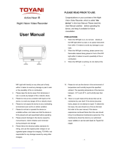
Figure 1: SEE™ camera with QuickConnect Mount/Cable
With an optional NIR illuminator and slow shutter speed selected, the SEE™ camera
provides a zero ambient light night vision solution at a distance of up to 500 feet in
Near InfraRed (NIR) mode.
NOTE: Fast moving objects will blur in the NIR mode.
ITAR AND EAR – EXPORT REGULATION COMPLIANCE
Warning: Some of the Commodities, Products, Technologies, and Services contained in this
document may be/are subject to one or more export control laws and regulations of the United
States Government and they fall under the control jurisdiction of either the U.S. Department of
State or the U.S. Bureau of Industry and Security – U.S. Department of Commerce. It is unlaw-
ful and strictly prohibited to export, or attempt to export or otherwise transfer or sell any hard-
ware or technical data or furnish any service to any foreign person, whether abroad or in the
United States, for which a license or written approval of the U.S. Government is required, with-
out first obtaining the required license or written approval from the appropriate Department of
the U.S. Government having jurisdiction in such matters. Diversion contrary to U.S. law is
prohibited.
About this Document
This manual contains instructions for setup and operation of the SEE™. The manual
is provided as a guide for field operations and should be read by the personnel set-
ting up or operating the SEE™.

Setup and Operations Manual SEE™
RVision P/N 660904-01 Rev 1 Page 3
Connecting the SEE™ Camera to a PC
The camera can be controlled with a personal computer running Windows XP and the
RVision pSEE™ application. See “Controlling the SEE™ Camera with pSEE™ Soft-
ware” on page 15 for detailed installation and operation instructions.
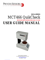
Figure 2: Connecting the SEE™ to the SEE2PC Integration Tool
Make sure the following is available.
• RVision SEE2PC Integration Tool.
• RVision QuickConnect mount/cable adapter.
• Power source.
HiDef
Connector
(male)
HiDef
Connector
(female) DC
Power
Source
RS232/422 DB9
Connector (male/female)
Video 1 – RCA
Video 2/Audio – RCA
Connectors (male)
Power
HiDef
Connector
(female)

SEE™ Setup and Operations Manual
Page 4 RVision P/N 660904-01 Rev 1
Click the hypertext link to jump to the page for detailed instructions about a proce-
dure.
1. “Mounting the QuickConnect Mount/Cable to a Pole” on page 4
2. “Mounting the Camera” on page 5
3. “Connecting the RS-232 connector to a PC” on page 7
4. “Connecting Power to the Camera” on page 8
5. “Connecting to the LOOK™ Controller” on page 8
6. “Running the pSEE™ Application” on page 12
7. “Connecting to Third Party Controllers” on page 13
Mounting the QuickConnect Mount/Cable to a Pole
The SEE™ is shipped with a QuickConnect Mount/Cable and the correct cable length
segment.
Figure 3: QuickConnect Mount Cable with a Thule clamp
To mount the QuickConnect Mount/Cable to a Thule rack perform the following
steps.
1. Loosen but do not remove QuickConnect fasteners.
2. Slide QuickConnect around horizontal Thule rack.
3. Tighten QuickConnect fasteners.
4. Route the QuickConnect cables to the computer or LOOK controller.
Note: Clamp mount assemblies include fasteners and a wrench.

Setup and Operations Manual SEE™
RVision P/N 660904-01 Rev 1 Page 5
Mounting the Camera
The base of the camera that slides into the rails located on the QuickConnect mount-
ing bracket.
NOTE: Dielectric grease is applied to the connector at the factory
to protect it from corrosion.
Perform the following steps to mount the camera
1. Slide Camera Base, the foot, into QuickConnect Rails, the shoe, until there is a
solid connection between their connectors.
Figure 4:Slide the camera foot into mount plates shoe
2. Tighten the security screw on the outside of the rail guide, using the hollow Allen
wrench provided with the system. Refer to Figure 4.
Testing the Mount
After securing the mounting screw, make sure the camera is firmly seated in the
QuickConnect mount by pulling on the eye bolt attached to the base of the camera.
Refer to Figure 5.
Camera
base
foot
mounting
screw
plunger
mounting

SEE™ Setup and Operations Manual
Page 6 RVision P/N 660904-01 Rev 1
Figure 5: Pull on the eye bolt to insure proper mount
Connecting the HiDef to Adapter to the SEE2PC Integration Tool
Attach the 15-pin male connector of the QuickConnect Cable to the SEE2PC female
counterpart.
The SEE2PC integration tool is a multiple cable adapter configured with many indus-
try standard connectors as called out in Figure 6.
Figure 6: SEE2PC Integration tool
Power RS232 RS422 Video
(yellow) Optional
Video/Audio
(red)
HiDef
female
connector

Setup and Operations Manual SEE™
RVision P/N 660904-01 Rev 1 Page 7
Using the RS422 to RS232 adapter
The RVision RS422 to RS232 adapter converts a 4-wire RS485/RS422 camera to an
RS232 output as shown in Figure 7, providing a standard RS232 connection to an
RS422 camera.
Figure 7: RS422 to RS232 Adapter
Connecting the RS-232 connector to a PC
The pSEE™ application requires an RS-232 serial port be reserved on the PC. The
following USB-to-serial port adapters can be used provided the following conditions
are met:
• Meets the RS-232 standards, not TTL.
• The adapter must be mapped to a COM port value less than nine (9).
Figure 8: Serial Port Connection to a PC
RS422 connector
(camera side)
RS232 connector
(controller side)

SEE™ Setup and Operations Manual
Page 8 RVision P/N 660904-01 Rev 1
Connecting Power to the Camera
NOTE: Before starting this procedure ensure that power is connected.
Refer to the camera specifications for the proper voltage input.
The following steps complete the SEE™ setup.
1. Attach SEE2PC DC power cable to the power supply plug.
Figure 9: SEE2PC Power Cable/Plug
2. Thread the collar of the power plug around the power jack.
Figure 10: Connecting the Power Cable/Plug
NOTE: Make sure that the collar of the power plug is fastened securely to
the threads of the DC power jack. The SEE™ camera performs a
calibration procedure when power is applied. The camera moves
left and down before returning to the default home position.
Connecting to the LOOK™ Controller
The RVison LOOK™ is a stand-alone controller with a Liquid Crystal Display (LCD)
that displays camera video, a joystick to control the pan/tilt/zoom function of the
base unit and attached camera, and a keypad for operator inputs.
DC
power cable
plug
DC
power supply
jack

Setup and Operations Manual SEE™
RVision P/N 660904-01 Rev 1 Page 9
CAUTION: Connect the video camera cable to the LOOK™ controller
before applying power. If power is applied to the LOOK™
controller before connecting the camera inputs, damage to
the LOOK™ controller or the camera may occur.
Run the Cables to Controller
The cable segment of the QuickConnect comes in different lengths from the factory.
Contact [email protected] for additional information about customized cable.
Connectors
The LOOK™ controller has four connectors located at the bottom of the unit as shown
in Figure 11.
Figure 11: Connector
Table 1 describes the function of the four connectors.
Table 1: LOOK™ Connectors functionality
Connectors Function
Camera Connects to the camera cable
Power Power source (DC only)
Video 1 Video 1 output
Video 2/Audio Video 2 output or microphone output (if equipped)
NOTE: The
Video 2/Audio
connector can be
used as a video or
audio output,
depending on the
camera
configuration.

SEE™ Setup and Operations Manual
Page 10 RVision P/N 660904-01 Rev 1
Connecting Power to the LOOK™ Controller
1. QuickConnect HiDef and power source lead connected to the LOOK™ controller.
Figure 12: Connect power to LOOK™ Controller
2. Connect the power connector from a cigarette lighter to the DC adapter. Refer to
Figure 13.
Figure 13: Connect power to the DC adapter
WARNING: Make sure that the camera mount is secured before
connecting power to the LOOK™ controller.
For detailed operational instructions refer to “Using the LOOK™ Controller” on
page 31.
DC
power
plug
DC
adapter

Setup and Operations Manual SEE™
RVision P/N 660904-01 Rev 1 Page 11
Connect the HiDef Connector to LOOK™
Plug the male DB9 connector of the QuickConnect cable to the female connector of
the LOOK™ joystick controller with LCD.
DO NOT apply power to the LOOK™ before mounting the camera!
Connect the LOOK™ to Power Source
Make sure the camera mount is secure before connecting power source to the
LOOK™ joystick controller with LCD.
HiDef connector
goes into “Camera”
port, upper-left
corner,
DO NOT plug the
power source to
the LOOK™ (shown
here, upper-right
corner) before
mounting the cam-
era!
Figure 14: HiDef connector

SEE™ Setup and Operations Manual
Page 12 RVision P/N 660904-01 Rev 1
Attach QuickConnect to Breakout Adapter
Connect Adapter to PC.
Install pSEE™
Go to “Installing pSEE™ Software” on page 15 for information on installing the
pSEE™ application.
Running the pSEE™ Application
Install the pSEE™ application as detailed in the “Installing pSEE™ Software” on
page 15.
Insert
HiDef
male con-
nector to
“break-
out”
female
input con-
nector on
the far
right of
Figure 15.
Figure 15 SEE2PC camera integration tool
Figure 16 Serial ports on a PC
/