Page is loading ...

Page 1
508054-01
03/2020
INSTALLATION INSTRUCTIONS FOR COMBUSTION AIR PRESSURE SWITCH KITS (19F44 & 20A87) USED WITH
SLP99UH090XV60C MODULATING GAS FURNACE
PRESSURE SWITCH
REPLACEMENT KIT
GAS UNITS
KITS & ACCESSORIES
WARNING
This conversion kit is to be installed by a licensed
professional service technician (or equivalent)
or other qualied agency in accordance with
the manufacturer’s instructions, all codes and
requirements of the authority having jurisdiction
in the USA, and the requirements of the CSA-B149
installation codes in Canada. If the information in
these instructions is not followed exactly, a re or
explosion may result causing property damage,
personal injury or loss of life. The qualied agency
performing this work assumes responsibility for
this conversion.
CAUTION
As with any mechanical equipment, contact with sharp
sheet metal edges can result in personal injury. Take
care while handling this equipment and wear gloves and
protective clothing.
Shipping and Packing List
Package 1 of 1 contains:
1 - Pressure Switch
Application
Pressure switch replacement kits (19F44 and 20A87) are
used with modulating furnaces. See table 1 for usage and
elevation.
TABLE 1
Kit Number and Elevation
SLP99 Model Kit Elevation (ft)
UH090XV60C 19F44 0-7500
20A87 7501-10,000
Installation
1 - Turnotheelectricalpowerandgassupplytothe
unit.
2 - Remove the heating compartment access panel.
3 - Remove the tubing and disconnect wires from the
existing pressure switch. Label wires and tubing
making note of tubing color and negative and
positive pressure switch ports.
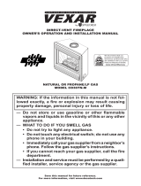
4 - Remove the existing pressure switch by carefully
pressing the tab which secures the switch assembly
tothecoldendheaderbox.Seegure1.
5 - Reconnect existing wires to replacement pressure
switch.
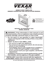
6 - Install replacement pressure switch. Reconnect
pressureswitchtubingasshowningure2.
7 - Replace access panel and restore the electrical
power and gas supply to the unit.
8 - Follow lighting instructions on unit nameplate.
REMOVING PRESSURE SWITCH
Pressure Switch Assembly
Tab
Negative Port
Positive Port
FIGURE 1
©2020

Page 2
SLP99UH090XV60C
(shown in upflow position)
Cold End Header Box
High-Fire Pressure
Switch
Low-Fire Pressure
Switch
1 - Black hose from front port on low-fire pressure switch to
positive port on the gas valve.
2 - Red and black hose from rear port on low-fire pressure
switch to the negative port on the gas valve.
3 - Red and black hose from front port on high-fire pressure
switch to negative port on cold end header box.
4 - Black hose from rear port on high-fire pressure switch to
positive port on cold end header box.
Gas Valve
1
2
3
4
FIGURE 2
NO
C
NO
C
PRESSURE SWITCHES
LOW
FIRE
HIGH
FIRE
PINK
PURPLE
PINK
VIOLET/PURPLE
To P58 12 pin
connector on the
integrated control
To P58 12 pin
connector on the
integrated control
To P58 12 pin
connector on the
integrated control
FIGURE 3
/