Page is loading ...

Page 1 © 2011 Lennox Industries Inc.
Litho U.S.A.
Corp. 1118−L4
Revised 11/2011 EL195UHE
Service Literature
EL195UHE SERIES UNITS
EL195UHE series units are high−efficiency gas fur-
naces manufactured with Lennox DuralokPlust alumi-
nized steel clamshell−type heat exchangers, with a stainless
steel condensing coil. EL195UHE units are available in
heating input capacities of 44,000 to 132,000 Btuh and
cooling applications from 2 through 5 tons. Refer to Engineer-
ing Handbook for proper sizing.
Units are factory equipped for use with natural gas. A kit is
available for conversion to LP/Propane operation. All
EL195UHE units are equipped with a hot surface ignition
system. The gas valve is redundant to assure safety
shut−off as required by C.S.A.
The heat exchanger, burners and manifold assembly can be
removed for inspection and service. The maintenance section
gives a detailed description on how this is done.
All specifications are subject to change. Procedures outlined
in this manual are presented as a recommendation only
and do not supersede or replace local or state codes.
WARNING
Electric shock hazard. Can cause injury
or death. Before attempting to perform
any service or maintenance, turn the
electrical power to unit OFF at discon-
nect switch(es). Unit may have multiple
power supplies.
Table of Contents
Specifications 2. . . . . . . . . . . . . . . . . . . . . . . . . . . . . . . . .
Optional Accessories 3. . . . . . . . . . . . . . . . . . . . . . . . . .
Blower Performance Data 4. . . . . . . . . . . . . . . . . . . . . .
I−Unit Components 7. . . . . . . . . . . . . . . . . . . . . . . . . . . .
II Placement and Installation 19. . . . . . . . . . . . . . . . . . . .
III−Start−Up 42. . . . . . . . . . . . . . . . . . . . . . . . . . . . . . . . . . .
IV−Heating System Service Checks 43. . . . . . . . . . . . . .
V−Typical Operating Conditions 46. . . . . . . . . . . . . . . . .
VI−Maintenance 47. . . . . . . . . . . . . . . . . . . . . . . . . . . . . . .
VII−Sequence of Operation and Flow Charts 50. . . . . .
WARNING
Improper installation, adjustment, alteration, service
or maintenance can cause property damage, person-
al injury or loss of life. Installation and service must
be performed by a licensed professional installer (or
equivalent), service agency or the gas supplier.
WARNING
Sharp edges.
Be careful when servicing unit to avoid sharp edges
which may result in personal injury.

Page 2
SPECIFICATIONS
Gas
Heating
Performance
Model No. EL195UH045XE36B EL195UH070XE36B EL195UH090XE48C
1 AFUE 95% 95% 95%
Input - Btuh 44,000 66,000 88,000
Output - Btuh 42,000 63,000 85,000
Temperature rise range - °F 25 - 55 40 - 70 40 - 70
Gas Manifold Pressure (in. w.g.)
Nat. Gas / LPG/Propane
3.5 / 10 3.5 / 10 3.5 / 10
High static - in. w.g. 0.5 0.5 0.5
Connections
in.
Intake / Exhaust Pipe (PVC) 2 / 2 2 / 2 2 / 2
Gas pipe size IPS 1/2 1/2 1/2
Condensate Drain Trap (PVC pipe) - i.d. 1/2 1/2 1/2
with furnished 90° street elbow 1/2 slip x 1/2 Mipt 1/2 slip x 1/2 Mipt 1/2 slip x 1/2 Mipt
with eld supplied (PVC coupling) - o.d. 1/2 slip x 1/2 Npt 1/2 slip x 1/2 Npt 1/2 slip x 1/2 Npt
Indoor
Blower
Wheel nom. dia. x width - in. 10 x 8 10 x 8 10 x 10
Motor output - hp 1/2 1/2 3/4
Tons of add-on cooling 1.5 - 3 1.5 - 3 2.5 - 4
Air Volume Range - cfm 360 - 1345 495 - 1380 715 - 1740
Electrical Data Voltage 120 volts - 60 hertz - 1 phase
Blower motor full load amps 6.8 6.8 8.4
Maximum overcurrent protection 12 12 12
Shipping Data lbs. - 1 package 129 136 160
NOTE - Filters and provisions for mounting are not furnished and must be eld provided.
1 Annual Fuel Utilization Efciency based on DOE test procedures and according to FTC labeling regulations. Isolated combustion system rating for non-weatherized
furnaces.
SPECIFICATIONS
Gas
Heating
Performance
Model No. EL195UH110XE60C EL195UH135XE60D
1 AFUE 95% 95%
Input - Btuh 110,000 132,000
Output - Btuh 105,000 126,000
Temperature rise range - °F 40 - 70 45 - 75
Gas Manifold Pressure (in. w.g.)
Nat. Gas / LPG/Propane
3.5 / 10 3.5 / 10
High static - in. w.g. 0.5 0.5
Connections
in.
Intake / Exhaust Pipe (PVC) 2 / 2 2 / 2
Gas pipe size IPS 1/2 1/2
Condensate Drain Trap (PVC pipe) - i.d. 1/2 1/2
with furnished 90° street elbow 1/2 slip x 1/2 Mipt 1/2 slip x 1/2 Mipt
with eld supplied (PVC coupling) - o.d. 1/2 slip x 1/2 Npt 1/2 slip x 1/2 Npt
Indoor
Blower
Wheel nom. dia. x width - in. 11-1/2 x 10 11-1/2 x 10
Motor output - hp 1 1
Tons of add-on cooling 3 - 5 3.5 - 5
Air Volume Range - cfm 1010 - 2220 1235 - 2405
Electrical Data Voltage 120 volts - 60 hertz - 1 phase
Blower motor full load amps 10.9 10.9
Maximum overcurrent protection 12 12
Shipping Data lbs. - 1 package 170 187
NOTE - Filters and provisions for mounting are not furnished and must be eld provided.
1 Annual Fuel Utilization Efciency based on DOE test procedures and according to FTC labeling regulations. Isolated combustion system rating for non-weatherized
furnaces.

Page 3
OPTIONAL ACCESSORIES - MUST BE ORDERED EXTRA
“B” Width
Models
“C” Width
Models
“D” Width
Models
CABINET ACCESSORIES
Horizontal Suspension Kit - Horizontal only 51W10 51W10 51W10
Return Air Base - Upow only 50W98 50W99 51W00
CONDENSATE DRAIN KITS
Condensate Drain Heat Cable 6 ft. 26K68 26K68 26K68
24 ft. 26K69 26K69 26K69
50 ft. 26K70 26K70 26K70
Heat Cable Tape Fiberglass - 1/2 in. x 66 ft. 36G53 36G53 36G53
Aluminum foil - 2 in. x 60 ft. 16P89 16P89 16P89
Crawl Space Vent Drain Kit 51W18 51W18 51W18
FILTER KITS
1 Air Filter and
Rack Kit
Horizontal (end) Size of lter - in. 87L96 - 18 x 25 x 1 87L97 - 20 x 25 x 1 87L98 - 25 x 25 x 1
Side Return Single 44J22 44J22 44J22
Ten Pack 66K63 66K63 66K63
Size of lter - in. 16 x 25 x 1 16 x 25 x 1 16 x 25 x 1
NIGHT SERVICE KIT
Night Service Kit 84W84 84W84 84W84
Safety Service Kit 89W20 89W20 89W20
TERMINATION KITS
See Installation Instructions for specic venting information.
Termination Kits -
Direct Vent
Applications Only
Concentric US - 2 in. 71M80 69M29 - - -
3 in. - - - 60L46 60L46
Canada - 2 in. 44W92 44W92 - - -
3 in. - - - 44W93 44W93
Flush-Mount 2, 2-1/2 or 3 in. 51W11 51W11 51W11
Wall - Close
Couple
US - 2 in. 22G44 - - - - - -
3 in. 44J40 44J40 44J40
Wall - Close
Couple WTK
Canada - 2 in. 30G28 - - - - - -
3 in. 81J20 81J20 81J20
Termination Kits -
Direct or Non-
Direct vent
Roof 2 in. 15F75 15F75 - - -
Wall Ring Kit 2 in. 15F74 3 15F74 - - -
Roof Termination Flashing Kit - Direct or
Non-Direct Vent (2 ashings)
2 in. 44J41 44J41 44J41
1 Cleanable polyurethane frame type lter.
2 Kits contain enough parts for two, non−direct vent installations.
3 Non−direct vent only.
NOTE - Termination Kits 44W92, 44W93, 30G28, 81J20 are certied to ULC S636 standard for use in Canada only.
GAS HEAT ACCESSORIES
Input
High Altitude
Pressure Switch Kit
Natural Gas to
LPG/Propane Kit
LPG/Propane
to Natural Gas Kit
Natural Gas
High Altitude
Orice Kit
LPG/Propane
High Altitude
Orice Kit
4501 - 7500 ft. 7501 - 10,000 ft. 0 - 7500 ft. 0 - 7500 ft. 7501- 10,000 ft. 7501- 10,000 ft.
045 No Change 80W60 69W73 73W81 73W37 68W68
070 80W66 80W59 69W73 73W81 73W37 68W68
090 80W65 80W59 69W73 73W81 73W37 68W68
110 80W66 80W59 69W73 73W81 73W37 68W68
135 80W65 80W59 69W73 73W81 73W37 68W68

Page 4
BLOWER DATA
EL195UH045XE36B PERFORMANCE (Less Filter)
External
Static
Pressure
in. w.g.
Air Volume / Watts at Various Blower Speeds
High Medium-High Medium Medium-Low Low
cfm Watts cfm Watts cfm Watts cfm Watts cfm Watts
0.00 1345 340 1255 245 1150 185 895 105 845 95
0.10 1305 345 1225 250 1105 200 855 110 810 95
0.20 1290 360 1190 260 1080 205 825 120 780 105
0.30 1275 370 1150 270 1045 215 785 125 720 110
0.40 1220 385 1120 280 1015 220 735 135 690 120
0.50 1215 390 1090 290 980 230 705 140 635 125
0.60 1190 395 1060 300 950 240 650 150 600 135
0.70 1140 390 1015 300 900 250 620 155 555 140
0.80 1100 380 1000 310 870 260 580 160 520 145
0.90 970 345 930 305 825 260 535 165 460 150
EL195UH070XE36B PERFORMANCE (Less Filter)
External
Static
Pressure
in. w.g.
Air Volume / Watts at Various Blower Speeds
High Medium-High Medium Medium-Low Low
cfm Watts cfm Watts cfm Watts cfm Watts cfm Watts
0.00 1380 315 1305 250 1190 200 965 105 920 100
0.10 1360 325 1270 255 1180 205 915 115 865 100
0.20 1310 335 1250 265 1130 215 880 120 815 110
0.30 1275 340 1205 275 1100 225 835 125 775 115
0.40 1250 355 1175 280 1065 230 795 135 730 125
0.50 1215 370 1145 295 1045 240 745 145 670 130
0.60 1200 380 1100 310 995 245 705 150 640 140
0.70 1145 380 1070 310 960 255 670 160 585 145
0.80 1070 370 1035 320 925 265 610 165 550 155
0.90 1015 365 1005 330 880 270 580 175 495 155
EL195UH090XE48C PERFORMANCE (Less Filter)
External
Static
Pressure
in. w.g.
Air Volume / Watts at Various Blower Speeds
High Medium-High Medium Medium-Low Low
cfm Watts cfm Watts cfm Watts cfm Watts cfm Watts
0.00 1740 370 1505 250 1370 195 1285 160 1135 125
0.10 1695 390 1470 265 1325 205 1240 170 1090 135
0.20 1660 405 1435 280 1290 220 1195 185 1045 145
0.30 1615 415 1390 295 1240 235 1140 200 995 160
0.40 1590 425 1350 305 1200 245 1110 210 945 165
0.50 1560 440 1310 320 1155 260 1055 225 895 175
0.60 1525 455 1255 335 1105 270 1005 230 855 190
0.70 1475 470 1220 340 1065 285 960 245 805 200
0.80 1410 470 1170 355 1010 295 920 255 760 210
0.90 1305 430 1130 370 985 305 875 265 715 220

Page 5
BLOWER DATA
EL195UH110XE60C PERFORMANCE (Less Filter)
External
Static
Pressure
in. w.g.
Air Volume / Watts at Different Blower Speeds
Bottom Return Air, Side Return Air with Optional Return
Air Base, Return Air from Both Sides or Return Air from
Bottom and One Side.
Single Side Return Air − Air volumes in bold require eld
fabricated transition to accommodate 20 x 25 x 1 in. air lter
in order to maintain proper air velocity.
High Med-High Medium Med-Low Low High Med-High Medium Med-Low Low
cfm Watts cfm Watts cfm Watts cfm Watts cfm Watts cfm Watts cfm Watts cfm Watts cfm Watts cfm Watts
0.00 2220 645 1940 435 1765 335 1635 280 1435 200 2185 655 1915 440 1745 340 1620 275 1430 195
0.10 2170 660 1920 460 1715 350 1595 290 1380 205 2160 660 1880 460 1705 345 1570 285 1380 205
0.20 2130 680 1865 475 1670 370 1560 305 1345 220 2115 680 1835 470 1670 365 1535 305 1325 220
0.30 2095 700 1835 490 1640 390 1525 325 1285 230 2060 705 1795 495 1630 380 1505 320 1285 230
0.40 2065 720 1785 510 1600 405 1465 335 1250 245 2050 720 1760 510 1570 400 1455 330 1235 245
0.50 2030 740 1755 525 1560 415 1425 355 1215 260 2000 740 1720 530 1535 415 1410 345 1195 260
0.60 1995 760 1705 550 1525 435 1380 370 1150 270 1955 760 1685 550 1505 435 1380 365 1145 275
0.70 1955 770 1660 560 1475 450 1350 375 1100 290 1935 775 1650 555 1455 450 1325 375 1100 285
0.80 1930 790 1635 575 1445 460 1300 395 1050 305 1890 790 1610 575 1425 460 1285 390 1055 295
0.90 1865 775 1580 595 1400 480 1250 410 1025 310 1840 780 1565 585 1390 475 1240 395 1010 310
EL195UH135XE60D PERFORMANCE (Less Filter)
External
Static
Pressure
in. w.g.
Air Volume / Watts at Different Blower Speeds
Bottom Return Air, Side Return Air with Optional Return
Air Base, Return Air from Both Sides or Return Air from
Bottom and One Side.
Single Side Return Air − Air volumes in bold require eld
fabricated transition to accommodate 20 x 25 x 1 in. air lter
in order to maintain proper air velocity.
High Med-High Medium Med-Low Low High Med-High Medium Med-Low Low
cfm Watts cfm Watts cfm Watts cfm Watts cfm Watts cfm Watts cfm Watts cfm Watts cfm Watts cfm Watts
0.00 2405 940 2235 735 2070 545 1830 390 1620 280 2395 925 2235 710 2020 550 1800 380 1610 275
0.10 2365 960 2210 745 2020 565 1770 400 1585 295 2360 935 2175 735 2005 555 1760 395 1550 295
0.20 2330 975 2180 770 1950 580 1745 420 1535 315 2350 955 2160 760 1955 565 1725 415 1510 300
0.30 2295 1000 2120 785 1925 595 1690 435 1480 325 2290 990 2095 775 1890 590 1700 435 1420 325
0.40 2275 1015 2075 805 1885 615 1640 460 1445 340 2255 995 2060 795 1850 615 1635 445 1390 340
0.50 2225 1025 2035 815 1845 630 1605 475 1395 360 2230 1010 2040 815 1845 625 1590 470 1375 360
0.60 2185 1010 2020 835 1815 645 1565 485 1330 365 2170 1025 2000 820 1795 640 1580 485 1335 370
0.70 2085 1005 1940 850 1735 665 1520 500 1310 385 2125 1010 1935 845 1725 660 1520 500 1295 385
0.80 2010 970 1890 860 1715 680 1465 510 1285 400 2025 980 1880 855 1705 680 1470 510 1260 405
0.90 1925 935 1830 840 1660 700 1415 530 1235 410 1945 935 1860 855 1695 695 1435 525 1220 410

Page 6
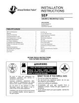
EL195UHE PARTS IDENTIFICATION
FIGURE 1
TOP CAP
BURNER BOX
ASSEMBLY
DuralokPlusTM
HEAT EXCHANGER
ASSEMBLY
CONTROL BOX
(includes integrated ignition control, trans-
former, circuit breaker and interlock switch)
COMBUSTION AIR
INDUCER
OUTER
ACCESS
PANEL COMBUSTION
AIR PRESSURE
SWITCH
PRIMARY LIMIT
GAS VALVE
BLOWER
ASSEMBLY
FLEXIBLE NO−HUB
EXHAUST COLLAR
COLD END
HEADER BOX
BAG ASSEMBLIES
(shipping location)
BLOWER ACCESS
PANEL

Page 7
I−UNIT COMPONENTS
ELECTROSTATIC DISCHARGE (ESD)
Precautions and Procedures
CAUTION
Electrostatic discharge can affect elec-
tronic components. Take precautions to
neutralize electrostatic charge by
touching your hand and tools to metal
prior to handling the control.
EL195UHE unit components are shown in figure 1. The
combustion air inducer, gas valve and burners can be ac-
cessed by removing the outer access panel. The blower
and control box can be accessed by removing the blow-
er access panel.
A−Control Box Components (Figure 2)
Unit transformer (T1) and integrated ignition control (A92)
are located in the control box. In addition, a door interlock
switch (S51) is located in the control box.
FIGURE 2
EL195UHE Control Box
Integrated Control
Door Interlock
Switch
Transformer
Circuit Breaker
1. Transformer (T1)
A transformer located in the control box provides power to
the low voltage section of the unit. The transformers on all
models are rated at 40VA with a 120V primary and 24V
secondary.
2. Door Interlock Switch (S51)
A door interlock switch rated 14A at 120VAC is located on
the control box. The switch is wired in series with line volt-
age. When the blower door is removed the unit will shut
down.
3. Circuit Breaker (CB8)
A 24V circuit breaker is also located in the control box. The
switch provides overcurrent protection to the transformer
(T1). The breaker is rated at 3A at 32V. If the current ex-
ceeds this limit the breaker will trip and all unit operation will
shutdown. The breaker can be manually reset by pressing
the button on the face.
4. Integrated Ignition Control (A92)
WARNING
Shock hazard.
Disconnect power before servicing. Control is not
field repairable. If control is inoperable, simply re-
place entire control.
Can cause injury or death. Unsafe operation will re-
sult if repair is attempted.
The hot surface ignition control system consisting of an in-
tegrated control (figure 3 with control terminal designa-
tions in tables 1, 2 and 3), sensor and ignitor (figure 5). The
integrated control and ignitor work in combination to en-
sure furnace ignition and ignitor durability. The integrated
control, controls all major furnace operations. The inte-
grated control also features a RED LED for troubleshoot-
ing and two accessory terminals rated at (1) one amp. See
table 4 for troubleshooting diagnostic codes. The nitride
ignitor is made from a non−porous, high strength propri-
etary ceramic material that provides long life and trouble
free maintenance.
TABLE 1
4−Pin Terminal Designation
PIN # FUNCTION
1Combustion Air Inducer Line
2Ignitor Line
3Combustion Air Inducer Neutral
4Ignitor Neutral
TABLE 2
12−Pin Terminal Designations
PIN # FUNCTION
1High Limit Output
2Not Used
324V Line
4Not Used
5Rollout Switch Out
624V Neutral
7High Limit Input
8 Ground
9Gas Valve Common
10 Pressure Switch In
11 Rollout Switch In
12 Gas Valve Out

Page 8
TABLE 3
1/4" QUICK CONNECT TERMINALS
120HUM Humidifier 120VAC
LINE 120VAC
XFMR Transformer 120VAC
CIRC Indoor blower 120VAC
EAC Indoor air quality accessory 120VAC
NEUTRALS Common 120VAC
HUM24 Humidifier 24VAC
3/16" QUICK CONNECT TERMINALS
COOL Cooling tap 24VAC
HEAT Heating tap 24VAC
FAN Continuous blower 24 VAC
PARK (no power) Park terminal for unused speed taps
FS Flame sense
24 COM Common 24VAC
TABLE 4
The integrated control is equipped with an LED light for troubleshooting. The diagnostic codes are listed below in table 4.
RED LED
Flash Code Diagnostic Codes / Status of Furnace
Off No power to control or board fault detected
On Board fault detected,
Heartbeat1Control powered − displayed during all modes of operation if no errors are detected
1Reverse Line Voltage Polarity
2Improper Earth Ground
3Burner failed to light, or lost flame during heat demand
4Low Flame Signal − check flame sensor
5Watchguard − burner failed to light, exceeded maximum number of retries or recycles.
6Not Used
7Primary or Secondary Limit Open or Watchguard Mode − Limit Switch Open longer than 3 min-
utes
8Rollout Switch Open
9Pressure Switch failed to close or opened during heat demand
10 Watchguard − Pressure Switch opened 5 times during one heat demand
11 Pressure Switch stuck closed prior to activation of combustion air inducer
12 Flame Sensed without gas valve energized
13 Low Line Voltage
Notes
Note 1 A "Heartbeat" is indicated by a "Slow Flash" − 1 sec on 1 sec off, repeating
Note Error codes are indicated by a "Rapid Flash" − the LED flashes X times at 1/2 sec on 1/2 sec
off, remains off for 3 sec, then repeats
Note
Last 10 error codes are stored in memory including when power is shut off to the unit. − To recall,
press and release button, most recent will be displayed first, LED off for 3 sec, then next error
code is displayed, etc. To clear error codes, depress and hold button longer than 5 seconds.

Page 9
FIGURE 3
INTEGRATED CONTROL
(Automatic Hot Surface Ignition System)
BLOWER OFF DELAY
RED LED RECALL BUTTON
Electronic Ignition
On a call for heat the integrated control monitors the com-
bustion air inducer pressure switch. The control board will
not begin the heating cycle if the pressure switch is closed
(by−passed). Once the pressure switch is determined to be
open, the combustion air inducer is energized. When the
differential in the pressure switch is great enough, the pres-
sure switch closes and a 15−second pre−purge begins. If
the pressure switch is not proven within 2−1/2 minutes, the
integrated control goes into Watchguard−Pressure Switch
mode for a 5−minute re−set period.
After the 15−second pre−purge period, the ignitor warms up
for 20 seconds during which the gas valve opens at 19 sec-
onds for a 4−second trial for ignition. The ignitor remains
energized for the first 3 seconds during the 4 second trial. If
ignition is not proved during the 4−second period, the inte-
grated control will try four more times with an inter purge
and warm−up time between trials of 35 seconds. After a to-
tal of five trials for ignition (including the initial trial), the inte-
grated control goes into Watchguard−Flame Failure mode.
After a 60−minute reset period, the integrated control will
begin the ignition sequence again.
Fan Time Control
Heating Fan On Time
The fan on time of 30 seconds is not adjustable.
Heating Fan Off Time
Fan off time (time that the blower operates after the heat
demand has been satisfied) can be adjusted by moving the
jumper to a different setting. The unit is shipped with a fac-
tory fan off setting of 90 seconds. For customized comfort,
monitor the supply air temperature once the heat demand
is satisfied. Note the supply air temperature at the instant
the blower is de−energized.
Adjust the fan−off delay to achieve a supply air temperature
between 90° − 110° at the instant the blower is de−ener-
gized. (Longer delay times allow for lower air temperature,
shorter delay times allow for higher air temperature). See
figure 4.
Cooling Fan On Time
The fan on time is 2 seconds and is not adjustable.
Cooling Fan Off Time
The control has a 45 second fan off delay after cooling de-
mand has been met. This delay is factory set and not ad-
justable.
HEAT FAN-OFF TIME IN SECONDS
To adjust fan−off timing, reposition jumper across pins to
achieve desired setting.
NO JUMPER
FIGURE 4
60
90
120
180
60
90
120
180
60
90
120
180
60
90
120
180
60 Second
off Time
90 Second
off Time
120 Second
off Time
180 Second
off Time

Page 10
FIGURE 5
EL195UHE Burner Box Assembly
Gas Valve
Burner Box Front
Rollout Switch(s)
Flame Sensor
Ignitor
Burner Assembly
B−Heating Components
Combustion air inducer (B6), primary limit control (S10), ig-
nitor, burners, flame rollout switch (S47), gas valve (GV1),
combustion air pressure switch (S18), and heat exchangers
are located in the heating compartment. The heating
compartment can be accessed by removing the outer ac-
cess panel.
1. Flame Rollout Switches (Figure 5)
Flame rollout switches S47 are SPST N.C. high temperature
limits located on the left and right of the front buner box plate.
S47 is wired to the burner ignition control A92. When ei-
ther of the switches sense flame rollout (indicating a
blockage in the combustion passages), the flame rollout
switch trips, and the ignition control immediately closes
the gas valve. Switch S47 in all EL195UHE units is factory
preset to open at 210_F + 12_F (99_C + 6.7_C) on a tem-
perature rise. All flame rollout switches are manual reset. See
table 4 flash code 8 for troubleshooting.
2. Heat Exchanger (Figure 6)
EL195UHE units use an aluminized steel primary and
stainless steel secondary heat exchanger assembly.
Heat is transferred to the air stream from all surfaces of
the heat exchanger. The shape of the heat exchanger en-
sures maximum efficiency.
The combustion air inducer pulls fresh air through the burn-
er box. This air is mixed with gas in the burners. The gas /
air mixture is then burned at the entrance of each clam-
shell. Combustion gases are then pulled through the primary
and secondary heat exchangers and exhausted out the ex-
haust vent pipe.
3. Primary Limit Control (Figure 6)
Primary limit (S10) used on EL195UHE units is located in the
heating vestibule panel. When excess heat is sensed in the
heat exchanger, the limit will open. Once the limit opens, the
furnace control energizes the supply air blower and de−en-
ergizes the gas valve. The limit automatically resets when
unit temperature returns to normal. The switch is factory
set and cannot be adjusted. For limit replacement remove
wires from limit terminals, remove mounting screws, rotate
limit switch 90 degrees and slowly remove from the vesti-
bule panel. Install replacement limit with same care. See
table 4 flash code 7 for troubleshooting if limit switch
opens during operation.

Page 11
FIGURE 6
Primary Limit Location and Heat Exchanger
Install limit face down
4. Gas Valve (Figure 7)
The EL195UHE uses an internally redundant valve to assure
safety shut-off. If the gas valve must be replaced, the same
type valve must be used.
24VAC terminals and gas control switch are located on
top of the valve. All terminals on the gas valve are con-
nected to wires from the ignition control. 24V applied to the
terminals opens the valve.
Inlet and outlet pressure taps are located on the valve. A
manifold adjustment screw is also located on the valve. An
LP/Propane changeover kit is available.
FIGURE 7
GAS VALVE SHOWN IN ON POSITION
MANIFOLD
PRESSURE
OUTLET
PORT
INLET
PRESSURE
PORT
MANIFOLD PRESSURE
ADJUSTMENT SCREW
(under barbed fitting)
5. Flame Sensor (Figure 5)
A flame sensor is located on the left side of the burner sup-
port. The sensor is mounted on the front burner box plate
and the tip protrudes into the flame envelope of the left−
most burner. The sensor can be removed for service (use
steel wool only to clean) without removing any part of the
burners. During operation, flame is sensed by current
passed through the flame and sensing electrode. The igni-
tion control allows the gas valve to remain open as long as
flame signal is sensed.
NOTE − The EL195UHE is polarity sensitive. Make sure
that the furnace is wired correctly and is properly grounded.
A microamp DC meter is needed to check the flame signal
on the integrated control.
Flame (microamp) signal is an electrical current which passes
from the integrated control to the sensor during unit operation.
Current passes from the sensor through the flame to ground to
complete a safety circuit.
To Measure Flame Signal − Integrated Control:
Use a digital readout meter capable of reading DC micro-
amps. See figure 8 for flame signal check.
1 − Set the meter to the DC amps scale.
2 − Turn off supply voltage to control.
3 − Remove sensor wire from integrated control.
4 − Connect (−) lead to flame sensor wire.
5 − Connect (+) lead to Terminal FS on integrated control.
6 − Turn supply voltage on and close thermostat contacts to
cycle system.
7 − When main burners are in operation for two minutes, take
reading.
6. Ignitor (Figure 5)
EL195UHE units use a nitride ignitor made from a propri-
etary ceramic material. To check ignitor, measure its resist-
ance and voltage. A value of 39 to 70 ohms indicates a
good ignitor. Voltage to the ignitor should be 102 − 132VAC.
See figure 9 for resistance and voltage checks.

Page 12
FIGURE 8
Measuring Flame Signal
Flame Signal In Microamps
Normal Low Drop Out
1.5 0.5 − 1.4 0.4
Set Dial to DC MicroAmps
(+)
Multi−Meter
(+)
(+) To Control
Sensor Terminal
(−) To Flame
Terminal
Flame Sensor
Terminal
Flame Sensor
Wire
Intergrated
Control
Remove sensor from integrated
control and connect alligator clip
(−) to flame sensor lead.
Remove sensor from integrated
control and connect alligator clip
(+) to terminal on control.

Page 13
FIGURE 9
Test 1
Check ignitor circuit for correct resistance.
Remove 4−pin plug from control.
Check ohms reading across terminals 2 and 4.
Reading should be between 39 and 70 ohms. If
value is correct, this is the only test needed.
If the reading on the meter is not correct, (0 or
infinity) then a second test is needed.
Test 2
Check ignitor for correct resistance.
Seperate the 2−pin jack−plug near the manifold and check
resistance of ignitor at the plug. Reading should be
between 39 and 70 ohms. If the reading is correct, then
the problem is with the wiring between the jack−plug and
the control. If reading is not correct, the issue is the ignitor.
Test 3
Check ignitor for correct voltage
Insert meter probes into terminals 2 and 4 (use small
diameter probes in order not to damage plug).
Check voltage during 20 second ignitor warm up period.
Voltage should read 120 volts + 10%. If voltage reads below
these values, check for correct supply voltage to furnace.
Multi−Meter
(set to ohms)
Multi−Meter
(set to ohms)
Multi−Meter
(set to VAC)

Page 14
7. Combustion Air Inducer (B6)
& Cold End Header Box
All EL195UHE units use a combustion air inducer to
move air through the burners and heat exchanger during
heating operation. The blower uses a shaded pole
120VAC motor. The motor operates during all heating op-
eration and is controlled by integrated control A92. Blower
operates continuously while there is a call for heat. The in-
tegrated control will not proceed with the ignition sequence
until combustion air inducer operation is sensed by the prov-
ing switches.
The combustion air inducer is installed on the cold end
header box. The cold end header box is a single piece
made of hard plastic. The box has an internal channel
where the combustion air inducer creates negative pres-
sure at unit start up. The channel contains an orifice used
to regulate flow created by the combustion air inducer.
The box has pressure taps for the combustion air inducer
pressure switch hoses. The pressure switch measures
the pressure across the combustion air inducer orifice or
difference in the channel and the box. If replacement is
necessary the gaskets used to seal the box to the
vestibule panel and the combustion air inducer to the
box, must also be replaced.
TABLE 5
EL195UHE Unit Combustion Air Inducer
Orifice Size
−045 0.618"
−070 0.810"
−090 0.973"
−110 1.040"
−135 1.235"
8. Combustion Air Pressure Switch
(Figure 10)
EL195UHE series units are equipped with a differential
pressure switch located on the cold end header box. The
switch monitors across the combustion air inducer orifice to in-
sure proper flow through the heat exchanger.
The switch is a SPST N.O. pressure switch electrically con-
nected to the integrated control. The purpose of the switch is
to prevent burner operation if the combustion air inducer is not
moving enough air for proper combustion.
FIGURE 10
Pressure Switch
On start-up, the switch monitors whether the combustion air
inducer is operating. It closes a circuit to the integrated
control when the difference in pressure across the com-
bustion air inducer orifice exceeds a non−adjustable factory
setting. If the switch does not successfully sense the re-
quired differential, the switch cannot close and the fur-
nace cannot operate. If the flue or air inlet become ob-
structed during operation, the switch senses a loss of
pressure differential and opens the circuit to the integrated
control. If the condensate line is blocked, water will back up
into the header box and reduce the pressure differential
across the switch. The pressure switch opens if the differ-
ential drops below the set point. See table 6.
Checks of pressure differential can aid in troubleshooting.
When measuring the pressure differential, readings should be
taken at the pressure switch. See figure 11and table 7. Lack of
differential usually indicates problems in the intake or exhaust
piping, but may indicate problems in the heat exchanger,
condensing coil, header boxes, combustion inducer or
other components.
TABLE 6
Unit
Altitude ft.
0 − 4500 4501 − 7500 7501 − 10000
Set Point w.c. Set Point w.c Set Point w.c.
−045 −0.65 −0.65 −0.60
−070 −0.90 −0.85 −0.65
−090 −0.90 −0.80 −0.65
−110 −0.90 −0.85 −0.65
−135 −0.90 −0.80 −0.65
*Set point is factory set and non−adjustable

Page 15
To Cold End Header Box
Field Provided Tubing
To Pressure Switch
To Cold End Header Box
FIGURE 11
1 − Remove thermostat demand and allow unit to
cycle off.
2 − Install a tee in the negative (−) line (red tubing) and a
tee in the positive (+) line (black tubing) running from
the pressure switch to the cold end header box.
3 − Install a manometer with hose from the negative (−)
side of the manometer to the tee installed in the
negative (−) line and with hose from the positive (+)
side of the manometer to the tee in the positive (+)
line.
NOTE − Both sides of the cold end header box are nega-
tive. However the (+) port reads less negative pressure
than the (−) port.
4 − Operate unit and observe manometer reading.
Readings will change as heat exchanger warms.
a. Take one reading immediately after start-up.
b. Take a second reading after unit has reached
steady state (approximately 5 minutes). This will be
the pressure differential.
The pressure differential should be greater
than those listed in table 6.
5 − Remove thermostat demand and allow to cycle off.
6 − Remove manometer and tee’s. Reinstall combustion
air sensing hoses to the pressure switch.
Measuring Pressure Differential
Black Tubing
(positive +)
Red Tubing
(negative −)
+"
High
−"
Low

Page 16
TABLE 7
Pressure Switch Troubleshooting Guide
Problem Corrective Action
Pressure switch stuck closed Check that the pressure switch is open without the combustion air inducer operat-
ing. Replace if defective.
Pressure switch does not close due to
obstruction in vent pipe.
Check for restricted vent. Remove all blockage.
Check for proper vent sizing. See table 11.
Pressure switch does not close due to
incorrect routing of the pressure
switch tubing.
Check that the pressure switch tubing is correctly routed. Correctly route pressure
witch line.
Pressure switch does not close due to
obstructions in the pressure switch
line.
Remove any obstructions from the the pressure switch line and/or taps
Pressure switch tubing damaged. Check pressure switch tubing for leaks. Replace damaged tubing if necessary.
Condensate in pressure switch tubing. Check pressure switch tubing for condensate. Remove condensate from tubing.
Pressure switch does not close due to
a low differential pressure across the
pressure switch.
Check the differential pressure across the pressure switch.
Check for restricted inlet vent. Remove all blockage.
Check for proper vent sizing and run length. See table11.
Wrong pressure switch installed in the
unit, or pressure switch is out of cal-
ibration
Check that the correct pressure switch is installed in the unit. Replace pressure
switch if necessary.
Miswiring of furnace or improper con-
nections at pressure switch.
Check for correct wiring and loose connections. Correct wiring and/or replace any
loose connections.
Pressure switch failure. If all the above modes of failure have been checked, the pressure switch may have
failed. Replace pressure switch and determine if unit will operate.
Damaged condensate trap. Check trap for any cracks or damage and replace if necessary.
Cold end header box does not drain
properly.
Check that the furnace is set properly with a slight tilt (0 − 1/2") towards the front
if necessary. See furnace installation instruction.
Air leakage around the combustion air
inducer gasket. Check gasket and replace if necessary.
Air leakage around the cold end head-
er box gasket. Check gasket and replace if necessary.
Damaged cold end header box tubing. Check tubing and replace if necessary.
DEMAND
CAI
GAS VALVE
15
ON
OFF
38
IGNITOR
341
Pre −Purge Ignitor Warm−up Trial for
Ignition Post
Purge
5 SEC80
*Blower on time will be 30 seconds after flame is sensed. Blower off time will depend on OFF TIME" Setting.
INDOOR BLOWER
Blower On"*
Delay
ELECTRONIC IGNITION
FIGURE 12

Page 17
C− Blower Compartment
IMPORTANT
Each blower is statically and dynamically bal-
anced as an assembly before installation in the
unit.
ML195UHE units are equipped with a constant torque ECM
motor. It has a DC motor coupled to an electronic control
module both contained in the same motor housing. The mo-
tor is programmed to provide constant torque at each of the
five selectable speed taps. Each tap requires 24 volts to en-
ergize.
Input Voltage Requirements
The circuit is designed to be operated with AC voltage. To
enable a tap requires 12 to 33VAC. Expected current draw
will be less than 20mA.
Troubleshooting
Troubleshooting the motor is an easy process. Follow
steps below.
1− Shut off power to unit.
2− Remove input plugs P48 and P49 from motor. See
figure 16 for troubleshooting procedure.
If correct voltage is present in tests 1 and 2 and motor is not
operating properly, replace motor. The motor is not field re-
pairable.
If replacing the indoor blower motor or blower wheel is nec-
essary, placement is critical. The blower wheel must be cen-
tered in the blower housing as shown in figure 13. When re-
placing the indoor blower motor the set screw must be
aligned and tightened with the motor shaft as shown in figure
14.
9. Secondary Limit Controls
The secondary limit is located in the blower compartment on
the back side of the blower housing. See figure 15. When ex-
cess heat is sensed in the blower compartment, the limit will
open. If the limit is open, the furnace control energizes the sup-
ply air blower and closes the gas valve. The limit automatically
resets when unit temperature returns to normal. The secon-
dary limit cannot be adjusted.
FIGURE 13
Center Blower Wheel
in Blower Housing
BLOWER WHEEL REPLACEMENT
FIGURE 14
Set Screw
Housing Hub
ALIGN AND TIGHTEN SET SCREW WITH
FLAT SIDE OF MOTOR SHAFT
Motor
Shaft
FIGURE 15
SECONDARY LIMIT CONTROL
Secondary Limits

Page 18
1
2
3
4
5
C
L
G
N
Multi−Meter
(set to VAC)
P48
P49
120
120
Turn on power to unit. Check for 120 volts across terminals
L" and N" on input plug P48. If voltage is present continue
to test 2. If voltage is not present problem may be may be up-
stream of plug P48 and proceed to test 3.
1
2
3
4
5
C
L
G
N
Multi−Meter
(set to VAC)
P48
P49 24
Switch thermostat to CONTINUOUS FAN MODE. Check for
24 volts across terminal C" on input plug P48and speed tap
used for continuous fan. (1, 2, 3, 4 or 5) on input plug P49. If
24 volts is not present problem may be up stream of plug P49.
Proceed to test 4.
Multi−Meter
(set to VAC)
120
120
24
Multi−Meter
(set to VAC)
Check for 24 volts across terminals 24 COM" and FAN" ter-
minals on the integrated control. If voltage is present, prob-
lem is with the harness. If voltage is not present problem
may be may be with the integrated control
Check for 120 volts across terminals CIRC" and Neutrals"
on the integrated control. If voltage is present, problem is
with the harness. If voltage is not present problem may be
may be with the integrated control.
Test 1
Test 2
Test 3 (if necessary)
Test 4 (if necessary)
FIGURE 16

Page 19
II−PLACEMENT AND INSTALLATION
Pipe & Fittings Specifications
All pipe, fittings, primer and solvent cement must conform
with American National Standard Institute and the Ameri-
can Society for Testing and Materials (ANSI/ASTM) stan-
dards. The solvent shall be free flowing and contain no
lumps, undissolved particles or any foreign matter that ad-
versely affects the joint strength or chemical resistance of
the cement. The cement shall show no gelation, stratifica-
tion, or separation that cannot be removed by stirring. Re-
fer to the table 8 below for approved piping and fitting ma-
terials.
CAUTION
Solvent cements for plastic pipe are flammable liq-
uids and should be kept away from all sources of
ignition. Do not use excessive amounts of solvent
cement when making joints. Good ventilation should
be maintained to reduce fire hazard and to minimize
breathing of solvent vapors. Avoid contact of cement
with skin and eyes.
TABLE 8
PIPING AND FITTINGS SPECIFICATIONS
Schedule 40 PVC (Pipe) D1785
Schedule 40 PVC (Cellular Core Pipe) F891
Schedule 40 PVC (Fittings) D2466
Schedule 40 CPVC (Pipe) F441
Schedule 40 CPVC (Fittings) F438
SDR−21 PVC or SDR−26 PVC (Pipe) D2241
SDR−21 CPVC or SDR−26 CPVC (Pipe) F442
Schedule 40 ABS Cellular Core DWV (Pipe) F628
Schedule 40 ABS (Pipe) D1527
Schedule 40 ABS (Fittings) D2468
ABS−DWV (Drain Waste & Vent)
(Pipe & Fittings) D2661
PVC−DWV (Drain Waste & Vent)
Pipe & Fittings) D2665
PRIMER & SOLVENT CEMENT ASTM
SPECIFICATION
PVC & CPVC Primer F656
PVC Solvent Cement D2564
CPVC Solvent Cement F493
ABS Solvent Cement D2235
PVC/CPVC/ABS All Purpose Cement For
Fittings & Pipe of the same material D2564, D2235, F493
ABS to PVC or CPVC Transition Solvent
Cement D3138
CANADA PIPE & FITTING & SOLVENT
CEMENT MARKING
PVC & CPVC Pipe and Fittings
ULCS636
PVC & CPVC Solvent Cement
ABS to PVC or CPVC Transition Cement
IMPORTANT
EL195UHE exhaust and intake connections are
made of PVC. Use PVC primer and solvent cement
when using PVC vent pipe. When using ABS vent
pipe, use transitional solvent cement to make con-
nections to the PVC fittings in the unit.
Use PVC primer and solvent cement or ABS solvent cement
meeting ASTM specifications, refer to Table 8. As an alter-
nate, use all purpose cement, to bond ABS, PVC, or CPVC
pipe when using fittings and pipe made of the same materi-
als. Use transition solvent cement when bonding ABS to ei-
ther PVC or CPVC.
Low temperature solvent cement is recommended during
cooler weather. Metal or plastic strapping may be used for
vent pipe hangers. Uniformly apply a liberal coat of PVC
primer for PVC or use a clean dry cloth for ABS to clean in-
side socket surface of fitting and male end of pipe to depth
of fitting socket.
Canadian Applications Only − Pipe, fittings, primer
and solvent cement used to vent (exhaust) this ap-
pliance must be certified to ULC S636 and supplied by a
single manufacturer as part of an approved vent (ex-
haust) system. In addition, the first three feet of vent
pipe from the furnace flue collar must be accessible for
inspection.

Page 20
TABLE 9
OUTDOOR TERMINATION KITS USAGE
EL195
UNIT
VENT
PIPE
DIA.
(in.)
STANDARD CONCENTRIC
Outdoor
Exhaust
Accelerator
(Dia. X
Length)
Outdoor
Exhaust
Accelerator
(Dia. X
Length)
2" Wall Plate
Kit
3" Wall Plate
Kit
2" Wall
Ring Kit
Flush-
Mount
Kit
1−1/2"
Concentric
Kit
2"
Concentric
Kit
3"
Concentric
Kit
1−1/2" X 12" 2" X 12" 22G44
or 30G28
44J40
or 81J2015F74 51W11**
71M80
or
44W92
69M29
or
44W92
60L46
or 44W93
045
2 YES YES YES* YES YES YES
2−1/2 YES YES YES* YES YES YES
3 YES YES YES* YES YES YES
070
2 YES YES YES* YES YES YES
2−1/2 YES YES YES* YES YES YES
3 YES YES YES* YES YES YES
090
2 YES YES YES YES YES YES
2−1/2 YES YES YES YES YES YES
3 YES YES YES YES YES YES
110
2 YES YES YES YES YES YES
2−1/2 YES YES YES YES YES YES
3 YES YES YES YES YES YES
135 3 YES YES YES YES
*Requires field−provided and installed 1−1/2" exhaust accelerator.
** Kit 51W11 is provided with a 1−1/2" accelerator which must be used for all EL195UHXE−045, −070 and −090 installations.
Termination kits 44W92, 44W93, 30G28 and 81J20 approved for use in Canadian installations to meet CSAB149.
The 44W92 concentric kit is provided with a 1−1/2" accelerator which must be installed on the exhaust outlet when this kit is used with the EL195UHXE04536B and
EL195UHXE070P36B furnaces.
NOTE − Standard terminations include all approved non−concentric terminations.
Joint Cementing Procedure
All cementing of joints should be done according to the
specifications outlined in ASTM D 2855.
DANGER
DANGER OF EXPLOSION!
Fumes from PVC glue may ignite during system
check. Allow fumes to dissipate for at least 5 minutes
before placing unit into operation.
1 − Measure and cut vent pipe to desired length.
2 − Debur and chamfer end of pipe, removing any ridges
or rough edges. If end is not chamfered, edge of pipe
may remove cement from fitting socket and result in a
leaking joint.
NOTE − Check the inside of vent pipe thoroughly for
any obstruction that may alter furnace operation.
3 − Clean and dry surfaces to be joined.
4 − Test fit joint and mark depth of fitting on outside of pipe.
5 − Uniformly apply a liberal coat of PVC primer for PVC or
use a clean dry cloth for ABS to clean inside socket
surface of fitting and male end of pipe to depth of fitting
socket.
NOTE − Time is critical at this stage. Do not allow prim-
er to dry before applying cement.
6 − Promptly apply solvent cement to end of pipe and in-
side socket surface of fitting. Cement should be ap-
plied lightly but uniformly to inside of socket. Take
care to keep excess cement out of socket. Apply sec-
ond coat to end of pipe.
7 − Immediately after applying last coat of cement to pipe,
and while both inside socket surface and end of pipe
are wet with cement, forcefully insert end of pipe into
socket until it bottoms out. Turn PVC pipe 1/4 turn dur-
ing assembly (but not after pipe is fully inserted) to dis-
tribute cement evenly. DO NOT turn ABS or cellular
core pipe.
NOTE − Assembly should be completed within 20 sec-
onds after last application of cement. Hammer blows
should not be used when inserting pipe.
/