Page is loading ...

1 2
4
6
8
0
3
5
7
9
INSTRUCTION MANUAL
AC-G43
WATERPROOF STAND-ALONE
ACCESS CONTROL UNIT
WITH BACKLIT KEYPAD
07/04

07/04
Replacing a lost Programming Code 40
Replacing a lost Normal / Secure Code 40
APPENDIX
Glossary 41
WARRANTY 44
TECHNICAL SUPPORT 46
Page 3
AC-G43
Page 2 07/04
Contents
INTRODUCTION 4
Technical Specifications 5
Key Features 6
INSTALLATION 8
Mounting the AC-G43 Controller 8
Wiring Diagrams 10
FEATURES AND CONCEPTS
Normal, Secure, & Master Users 14
Modes Of Operation 15
Changing the Modes of Operation 16
Auxiliary Output and Input 17
Request To Exit (REX) Button 18
Case and Back Tamper 18
BL-D40 External Sounder 19
PROGRAMMING THE AC-G43 20
Entering Programming Mode 21
Exiting Programming Mode 21
1 Changing the Open Code 22
2 Changing the Auxiliary Code 22
3 Changing the Programming Code 23
4 Changing the Normal / Secure Code 24
5 Changing the Normal / Bypass Code 24
Door Chime Settings 24
6 Setting Fail Safe / Secure Operation 26
Setting Tamper Siren Time 26
Setting the Lock Strike Release Time 26
Setting the Auxiliary Mode 27
Auxiliary Mode Quick Reference Table 28
Auxiliary Mode Reference Guide 29
7 Enrolling Primary and Secondary Codes 32
8 Deleting Primary and Secondary Codes 35
9 Lock Strike Relay and Auxiliary Relay 37
Code Assignment
0 Return to Factory Default Settings 39
AC-G43

Page 4 07/04
Introduction
Equipment provided
The following is provided as part of every AC-G43 package:
The AC-G43 is a waterproof keypad access control unit with backlit
keypad suitable for external or internal applications.
The unit accepts up to 500 users and provides entry via the use of
PIN codes.
- AC-G43 Access Control Unit.
- Installation Kit
- Installation and Operating Instructions
Additional Equipment Required
1) Electric Lock Strike Mechanism
Fail Safe (Power to Lock) or Fail Secure (Power to Open)
2) Power Supply with Backup Battery
12 to 24V DC (From a Regulated Power Supply)
or
16 to 24V AC (From a Transformer)
3) Request To Exit (REX) Button
Normally Open Type - Switch is closed when pressed.
4) BL-D40 External Sounder (Optional)
Provides Siren, Bell, and Chime functions to AC-G43
Other Rosslare accessories can be found at Rosslare's
Web Site:
http://www.rosslaresecurity.com
AC-G43 07/04
Technical Specification
Electrical Characteristics
Operating Voltage Range:
12 to 24V DC From a Regulated Power Supply
or
16 to 24V AC From a Transformer
Maximum Input Current:
Standby: 75mA Not including attached devices
Max: 135mA Not including attached devices
Relay Outputs:
Lock Strike Relay Form C, 5A
Auxiliary Relay Form C, 5A
Inputs:
REX N.O., Dry Contact
Auxiliary Input (In / Monitor) N.O., Dry Contact
LEDs
Two Tri-colored LEDs
Environmental Characteristics
Operating Temperature: -22 F to 150 F (-30 C to 65 C)
Operating Humidity: 0 to 95% (Non-Condensing)
Suitable for outdoor use. (IP 65)
Mechanical Characteristics
Dimensions:
5.39" (137mm) L x 1.73" (44mm) W x 1.14" (29mm) D
Weight:
0.39 lbs (178g)
Page 5
AC-G43

Page 6 07/04
Key Features
Here are some of the AC-G43's key features:
! Waterproof
! Built in backlit keypad for PIN code entry
! Auxiliary Input & Auxiliary Output
! Ten Auxiliary Modes including:
Door Ajar
Forced Door
Shunt
Door Monitor
Normal / Secure
LED Control
! Internal Buzzer
! Comes with security screw and security screw tool
! Two Tri Color LED'S for Status / Programming Interface LED's
! Three User Levels
Normal User
Secure User
Master User
! Three Modes of Operation
Normal Mode
Bypass Mode
Secure Mode
! "Code Search" feature that helps make maintaining user codes
easier.
! Input for Request to Exit (REX) button.
! Comes with mounting template for easier installation.
! Built in Case and Back Tamper
!Bell, Chime, Siren, and Strobe features available with BL-D40.
! Programmable Siren Time (with BL-D40)
! Programmable Lock Strike Release Time
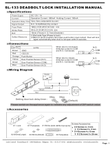
AC-G43
2 x 6 Matrix Backlit
Keypad
Case Screw
Door LED
Bell Button
(with BL-D40)
Mode LED
1 2
4
6
8
0
3
5
7
9

Page 8 07/04
AC-G43
Installation
Mounting the AC-G43 Controller
1) Before starting, select the location to mount the AC-G43
controller.
2) For wall mounting use the mounting template as a guide to drill
the mounting and cable holes in the wall. For US Gang Box
installation there are two holes on the back cover aligned for the
US Gang Box. (Shown marked as "A" in diagram below).
3) Screw the AC-G43 back cover to its mounting location.
4) Wire the controller according the wiring instructions of the
following page.
5) Mount the AC-G43 to the back cover.
6) Secure the AC-G43 by using the supplied security screw in the
Installation Kit. An L-Shaped tool is provided for use when
tightening the security screw.
Tamper
Lens
A
A
Page 9 07/04
Wiring the AC-G43
The controller is supplied with a 22" (60cm) pigtail, having a 10
conductor cable. To wire the Controller, perform the following
steps.
1) Prepare the controller cable to the required length.
2) Splice the controller pigtail wires to the corresponding devices
and cover each connection. Refer to the wire color guide
provided below and to the wiring diagrams provided on the
following pages.
Wire Color Guide
3) Trim and cover all conductors that are not used.
A few of the typical wiring diagrams are shown on the next three
pages; for other wiring diagram examples refer to the support
section of the Rosslare Web Site.
http://www.rosslaresecurity.com
AC-G43
RED
BLACK
GREEN
WHITE
BROWN
BLUE
YELLOW
ORANGE
PURPLE
GRAY
V INPUT
GROUND
REX / BL
IN / MONITOR
N.C.
LOCK: COM
N.O.
AUX: COM
N.O.
N.C.
LOCK:
LOCK:
AUX:
AUX:
COLOR DESCRIPTION

Wiring Diagrams
Page 10 07/04
AC-G43
(-)
ELECTRIC LOCK
STRIKE
COM
N.C.
N.O.
REX / BL
LOCK
V IN
REX / BL
(-)
(-)
(+)
(+)
FAIL SAFE
or
FAIL SECURE
REX
COMMON
POWER SUPPLY
12V - 24V DC
or
16V - 24V AC
FROM TRANSFORMER
{
GROUND BLACK
RED
GREEN
GRAY
BROWN
PURPLE
AC-G43
Transorb: 1.5KE47C - Connect to load terminals
(Optional transorb, Not Supplied)
07/04
Page 11
AC-G43
Wiring the Auxiliary Input and Output
IN / MONITOR
V IN
COMMON
POWER SUPPLY
(-)
(+)
12V - 24V DC
or
16V - 24V AC
FROM TRANSFORMER
Auxiliary
Load
AUXILIARY
INPUT
(MONITOR)
(-)
AUX. IN IN / MONITOR
COM
N.C.
N.O.
AUX.
{
GROUND BLACK
RED
WHITE
YELLOW
ORANGE
BLUE
AC-G43
Transorb: 1.5KE47C - Connect to load terminals
(Optional transorb for inductive loads, Not Supplied)

Page 12 07/04
Wiring the BL-D40 External Sounder
AC-G43
REX / BL
REX / BL
(+)
(-)
BL-D40
COMMON
POWER SUPPLY (-)
(+)
12V - 24V DC
or
16V - 24V AC
FROM TRANSFORMER
V IN
GROUND BLACK
RED
GREEN
AC-G43
Page 13 07/04
AC-G43
THIS PAGE IS INTENTIONALLY BLANK

Page 14 07/04
Normal, Secure, & Master Users
The AC-G43 accepts up to 500 users and provides entry via the
use of PIN codes. Each user is provided with two code memory
slots, Memory Slot 1 (Primary Code) and Memory Slot 2
(Secondary Code).
The way in which the two memory slots are programmed
determines a users access level and also determines the way in
which the AC-G43 grants access in its three Modes of Operation.
There are three user levels:
Normal User
A Normal User only has a Primary Code and is only
granted access when the AC-G43 is in Normal or
Bypass Mode.
Secure User
A Secure User must have a Primary and Secondary
Code programmed, the two codes must not be the
same. The Secure User can gain access when the
AC-G43 is in any of its three Modes of Operation. In
Normal Mode the Secure User must use their
Primary Code to gain entry. In Secure Mode the
Secure User must first present their Primary Code
and then their Secondary Code in order to gain
entry.
Master User
A Master User must have both Primary and
Secondary Codes programmed with the same
Proximity Card or PIN code. The Master User can
gain access during any Mode of Operation by
presenting their PIN code to the controller.
AC-G43 07/04
Page 15
AC-G43
Modes of Operation
!
The AC-G43 has 3 Modes of Operation:
1) Normal Mode.
Mode LED is green
Normal Mode is the default mode. In Normal Mode the door is
locked until a Primary Code is presented to the controller. The
controller can only be programmed in Normal Mode.
2) Bypass Mode.
! Mode LED is orange
In Bypass Mode, access to the premises is dependent on
whether the controller's Lock Strike Relay is programmed for Fail
Safe Operation or Fail Secure Operation.
When the Lock Strike Relay is programmed for
Fail Secure Operation, the door is locked until the Star
button is pressed.
When the Lock Strike Relay is programmed for
Fail Safe Operation, the door is constantly unlocked.
In case of power failure, for security reasons when power is
restored the controller will be in Normal Mode.
3) Secure Mode.
! Mode LED is red
Only Secure and Master Users can access the premises during
the Secured Mode.
Mode Door
GREEN
Mode Door
ORANGE
Mode Door
RED
A Secure User must enter their Primary and
Secondary Codes to gain entry. After entering their Primary
code the Door LED will flash green for 10 seconds, during
which the Secondary Code must be entered. A Master User
only needs to present their Proximity Cord or PIN code once to
gain entry.

Page 16 07/04
Changing the Modes of Operation
Changing from Normal Mode to Secure Mode:
The default factory setting for the Normal / Secure Code is 3838
1) Enter the 4-digit Normal / Secure
Code
! Mode LED will flash red
2) Press the "#" key to confirm
the Mode change.
! Mode LED is red
Changing from Secure Mode to Normal Mode:
The default factory setting for the Normal / Secure Code 3838
1) Enter the 4-digit Normal / Secure
Code.
! Mode LED will flash green.
2) Press the "#" key to confirm
the Mode change.
! Mode LED will turn green.
The Auxiliary Input of the AC-G43 can also be used to switch the
mode of operation from Secure to Normal Mode and vice versa.
Refer to "Setting the Auxiliary Mode" on Page 27.
AC-G43
Mode Door
GREEN
Mode Door
RED
Mode Door
RED
Mode Door
Mode Door
Mode Door
RED
GREEN
GREEN
07/04
Changing from Normal Mode to Bypass Mode:
By default there is no Normal / Bypass Code. The Normal / Bypass
Code must first be programmed to use this function. Refer to page
24 to create / modify the Normal / Bypass Code.
1) Enter the 4 digit Normal / Bypass
Code.
! Mode LED will flash orange
2) Press the "#" key to confirm
the Mode change.
! Mode LED will turn orange
Changing from Bypass Mode to Normal Mode:
1) Enter the 4 digit Normal / Bypass
Code.
! Mode LED will flash green
2) Press the "#" key to confirm
the Mode change.
! Mode LED will turn green
The AC-G43 auxiliary input and output can be configured in ten
different modes of operation, for optimum usability in different
applications.
For more information, refer to "Setting the Auxiliary Mode" on Page
27.
Auxiliary Input and Output
Page 17
AC-G43
Mode Door
GREEN
Mode Door
Mode Door
ORANGE
Mode Door
GREEN
Mode Door
ORANGE
Mode Door
ORANGE
GREEN

Page 18 07/04
Request to Exit (REX) Button
Case and Back Tamper
The REX button must be located inside the premises to be secured
and is used to open the door without the use of a PIN code, it is
usually located in a convenient location, e.g. Inside the door or at a
receptionist's desk. The function of the REX button depends on
whether the Lock Strike Relay is programmed for Fail Safe
Operation or Fail Secure Operation. The door chime in the BL-D40
does not sound when the REX button is used to open the door.
1) Fail Secure Operation: From the moment the REX button is
pressed, the door will be unlocked until the "Lock Strike Release
Time" has passed. After this time, the door will be locked even if
the REX button has not been released.
2) Fail Safe Operation: From the moment the REX button is
pressed, the door will be unlocked until the REX button is
released, plus the "Lock Strike Release Time". In this case the
"Lock Strike Relay" only begins its count down once the REX
button has been released. This feature is designed to keep the
door open when used in conjunction with fire sytems.
If the case of the controller is opened or the controller is removed
from the wall, a tamper event is triggered and a coded tamper
signal is sent to a BL-D40, Supply, or other compatible device.
If the BL-D40 External Sounder receives a Tamper Event Signal, it
will activate a Siren and a Strobe Light. The Siren time can be
easily programmed in the AC-G43 from 0 to 9 minutes.
The tamper event can activate the Auxiliary Output if the controller
is in Auxiliary Mode 3. Refer to "Setting the Auxiliary Mode" on
Page 27.
Clearing a tamper event is done by entering a valid User Code.
AC-G43 07/04
BL-D40 External Sounder
The BL-D40 External Sounder is designed to operate indoors and
installed within the premises to be secured. The Sounder can be
powered by 12 to 24V DC power supply or by 16 to 24V AC from a
transformer.
The BL-D40 is capable of emitting four different types of alerts both
audible and visual; Bell, Door Chime, Siren, and Strobe Light.
1) The Bell always sounds when the controller's doorbell button
is pressed.
2) The Door Chime can be programmed to sound whenever a
valid code is entered.
3) The Siren can be programmed to sound when the case of the
controller is tampered i.e. opened or when the controller is
removed from the wall. The controller can also program the
length of the Siren Time in the BL-D40.
The Controller communicates with the BL-D40 using a coded
proprietary Rosslare communications protocol. This provides a
more secure link between the Controller and the BL-D40.
If the BL-D40 receives any unrecognized codes on its
communication line or communication between the controller and
the BL-D40 are severed, the Strobe with flash repeatedly until the
communication problem has been resolved.
Page 19
AC-G43

Programming the AC-G43
Programming the AC-G43 is done solely via the unit's keypad
driven Programming Menu System. To reach the Programming
Menu System the AC-G43 must first be placed into Programming
Mode. See "Entering Programming Mode" on Page 21 for more
information.
During the AC-G43's manufacturing process certain codes and
settings are pre-programmed. These settings are the called the
"Default Factory Settings".
The table below shows the names of all the AC-G43 Menus. It also
shows of all the AC-G43's default factory codes and settings.
Programming Menu
2580 Change Open Code 1 1
0852 Change Auxiliary Code 2
1234 Change Program Code 3
3838 Change Normal / Secure Code 4
Change Normal / Bypass Code 5
0004 Change Lock Strike Release Time 6
2004 Define Auxiliary Inputs / Outputs
Enroll PIN Code. 7
Delete PIN Code 8
Code Assignment with Strike/Auxiliary 9
Return to Default Factory Setting 0
You will find a complete description and instructions for each of the
above menu items on the following pages.
Page 20 07/04
AC-G43
Menu Description
Factory
Settings
Menu
Number
Page 21 07/04
Entering Programming Mode
Exiting Programming Mode
1) Press the "#" key two times
within 2 seconds.
! Mode LED will turn off
! Door LED will turn red
2) Enter your 4-digit Programming
Code.
If the Programming Code
is valid the door LED will turn
green and the AC-G43 will be in
Programming Mode.
Note: - The AC-G43 must be in Normal Mode to enter the
Programming Mode.
- The factory default Programming Code is 1234
- If a Programming Code is not entered within 5 seconds,
the AC-G43 will return to Normal Mode.
1) To exit the Programming Mode at any time:
Press the "#" key
! You will hear 1 long beeps.
! The Door LED will be off
! The Mode LED will turn green
This indicates that the AC-G43 has returned to Normal Mode.
2) Wrong entries may reset the controller back to Normal Mode.
3) While in Programming Mode if no key is pressed for 1 minute the
AC-G43 will exit programming mode and return to Normal Mode.
4) While in enrolling user, deleting users, or code assignment
modes, to exit Progrmming Mode press the "#" key two times.
AC-G43
Mode Door
Mode Door
GREEN
RED
1 2 34
Mode Door
GREEN

Changing the Open Code
Changing the Auxiliary Code
The Open Code is mainly used as a method to quickly test the
Lock Strike Relay during installation.
The Default Factory Setting for the Open Code is 2580.
When the first user is added to the controller, the default Open
Code will automatically be deleted, ready for a new Open Code
to be re-entered.
1) Enter Programming Mode
2) Press "1" to enter Menu 1
! The Mode LED will turn red
3) Enter the new 4-digit code you
wish to set as Open Code.
4) System returns to Normal Mode
! You will hear three beeps
! The Door LED will turn off
! The Mode LED will turn green
Note: - Open Code does not function in Secure Mode.
- Wrong entries: you will hear a long beep and the
controller will return to Normal Mode.
- Code 0000 will erase and deactivate the Open Code.
The Auxiliary Code is mainly used as a method to quickly test the
Auxiliary Relay during installation.The Default Factory Setting for
the Auxiliary Code is 0852.
For security reasons when the first user is added to the controller
or the open code is changed, the default Auxiliary Code will
automatically be deleted, ready for a Auxiliary Code to be
assigned.
Page 22 07/04
AC-G43
Mode Door
GREEN
Mode Door
GREEN
RED
????
Mode Door
GREEN
Page 23 07/04
1) Enter Programming Mode
2) Press "2" to enter Menu 2
! The Mode LED will turn red
3) Enter the new 4-digit code you
wish to set as Auxiliary Code.
4) System returns to Normal Mode
! You will hear three beeps
! The Door LED will turn off
! The Mode LED will turn green
Note: - Auxiliary Code does not work in Secure Mode.
- Auxiliary Code only works when the Auxiliary Mode is 0,
1, 8 or 9.
- Code 0000 will erase and deactivate the Auxiliary
Code.
1) Enter Programming Mode
2) Press "3" to enter Menu 3
! The Mode LED will turn green.
3) Enter the new 4-digit code you
wish to set as Programming Code
4) System returns to Normal Mode
! You will hear three beeps
! The Door LED will turn off
! The Mode LED will turn green
Note: - Programming Code can not be erased, i.e. the code
0000 is not valid and will not erase the Programming
Code.
Changing the Programming Code
AC-G43
Mode Door
Mode Door
GREEN
GREEN
Mode Door
GREENGREEN
????
Mode Door
GREEN
Mode Door
GREEN
Mode Door
GREEN
????
ORANGE

Changing the Normal / Secure Code
Changing the Normal / Bypass Code
and Door Chime Settings
1) Enter Programming Mode
2) Press "4" to enter Menu 4
! The Mode LED will flash red
3) Enter the new 4-digit code you
wish to set as Normal / Secure Code
4) System returns to Normal Mode
! You will hear three beeps
! The Door LED will turn off
! The Mode LED will turn green
Note: - When the Auxiliary Mode is 1, 2, 3, or 4 the Auxiliary
Input takes priority over the Normal / Secure Code.
The Normal / Bypass Code is also used to turn the Door Chime off
and on. Chime only functions with BL-D40 External Sounder.
1) Enter Programming Mode
2) Press "5" to enter Menu 5
! The Mode LED will flash orange.
3) Below is a list of the four different ways that the Normal / Bypass
Code and Door Chime can be programmed.
a) Disable Bypass Mode - Disable Door Chime
b) Disable Bypass Mode - Enable Door Chime
c) Enable Bypass Mode - Disable Door Chime
d) Enable Bypass Mode - Enable Door Chime
Page 24 07/04
AC-G43
Mode Door
GREEN
Mode Door
GREEN
RED
????
Mode Door
GREEN
Mode Door
GREEN
Mode Door
GREEN
ORANGE
Page 25 07/04
a) Disable Bypass Code - Disable Door Chime
Enter the 4-digit code 0000
b) Disable Bypass Code - Enable Door Chime
Enter the 4-digit code 0001
c) Enable Bypass Code - Disable Door Chime
Enter any 4-digit code ending with 0
d) Enable Bypass Code - Enable Door Chime
Enter any 4-digit code not ending with 0
4) System returns to Normal Mode
! You will hear three beeps
! The Door LED will turn off
! The Mode LED will turn green
Note: - The chime is only generated when the Lock
Strike Relay is activated due to a valid code entry.
AC-G43
Mode Door
GREEN
0001
0000
???0
???0

Page 27 07/04
Setting the Auxiliary Mode
The default auxiliary setting is 2004.
1) Enter Programming Mode
2) Press "6" to enter Menu 6
! The Mode LED will flash green
3) Construct the 4-digit code
using the instructions below:
Auxiliary Mode
Auxiliary Setting
Auxiliary Mode
In addition to the Lock Strike Relay and Lock Strike REX, the
AC-G43 features an Auxiliary Output Relay and an Auxiliary
Input. The Auxiliary Mode defines the function of the Auxiliary
Input and Output.
The Auxiliary Mode also determines if the Auxiliary Output Relay
is set for Fail Safe or Fail Secure Operation.
Auxiliary Settings
Each of the Auxiliary Modes has a two digit setting that affects
how the Auxiliary Mode functions.
4) System returns to Normal Mode
! You will hear three beeps
! The Door LED will turn off.
! The Mode LED will turn green
The Auxiliary Mode Quick Reference Table can be found on
the next page. For a more detailed explanation on each
auxiliary mode refer to the "Auxiliary Mode Reference
guide" on Page 29.
AC-G43
Mode Door
GREEN
Mode Door
GREENGREEN
2???
Mode Door
GREEN
Setting Fail Safe/Secure Operation
Setting Tamper Siren Time
Setting the Lock Strike Release Time
The default factory setting is 0004.
The Tamper Siren feature requires the BL-D40 External Sounder.
1) Enter Programming Mode
2) Press "6" to enter Menu 6
! The Mode LED will flash green
3) Construct the 4-digit code
using the instructions below:
First Digit
For Fail Secure Operation the first
digit should be "0"
For Fail Safe Operation the first
digit should be "1"
Second Digit
Tamper Siren Time, enter any
number from 0 to 9 minutes.
Third and Fourth Digit
Enter the number of seconds from
(1 to 99 seconds) that you want
the Lock Strike to be released.
For example 0 5 1 2 means Fail Secure Operation, with a 5
minute Tamper Siren Time, and a 12 second Lock Strike release
time.
4) System returns to Normal Mode
! You will hear three beeps
! The Door LED will turn off.
! The Mode LED will turn green
Page 26 07/04
AC-G43
Mode Door
GREEN
Mode Door
GREEN
Mode Door
GREEN
GREEN
????

Page 29 07/04
Auxiliary Mode Reference Guide
The following are brief descriptions of each of the AC-G43's
auxiliary modes. To use these features refer to "Setting the Auxiliary
Mode" on page 27.
AUXILIARY MODE 0
In auxiliary mode 0 the AC-G43 can function as a two door
controller. The auxiliary relay should be attached to the lock on the
second door. The auxiliary setting defines the door open time for
the second door. The auxiliary input should be attached to the REX
button for the second door.
AUXILIARY MODE 1
In auxiliary mode 1 the AC-G43 can function as a two door
controller. The auxiliary relay should be attached to the lock on the
second door. The auxiliary setting defines the door open time for
the second door. The auxiliary input can switch the mode of
operation of the controller between Normal and Secure Mode. By
connecting a switch timer to the auxiliary input you can for example
automatically switch the AC-G43 from Normal Mode during office
hours to Secure mode after office hours.
AUXILIARY MODE 2
In auxiliary mode 2 the auxiliary relay can function as a general
purpose timed switch that can be activated when the star button on
the AC-G43 is pressed. The auxiliary setting defines how long the
auxiliary relay should be activated. The auxiliary input can switch
the mode of operation of the controller between Normal and Secure
Mode. By connecting a switch timer to the auxiliary input you can
for example automatically switch the AC-G43 from Normal Mode
during office hours to Secure mode after office hours.
AUXILIARY MODE 3
In auxiliary mode 3 the auxiliary output is activated if the AC-G43 is
tampered, i.e. the case tamper or back tamper is triggered. The
auxiliary input can switch the mode of operation of the controller
AC-G43
Auxiliary
Mode
Auxiliary Mode Quick Reference Table
0REX-2 Valid Code or REX-2 N.O. 01 to 99 Aux. Relay Release Time
00 Aux. Relay Toggles
1Normal / Secure Valid Code N.O. 01 to 99 Aux. Relay Release Time
00 Aux. Relay Toggles
2Normal / Secure Star Button N.O. 01 to 99 Aux. Relay Release Time
00 Aux. Relay Toggles
3Normal / Secure Tamper Event N.C. 01 to 99 Aux. Relay Release Time
00 Aux. Relay activated by Tamper
4Normal / Secure Direct Shunt N.O. 00 to 99 Shunt Time
5Door Monitor Shunt N.C. 00 to 99 Maximum Shunt Time
6Door Monitor Forced Door N.C. 00 to 99 Forced Delay
7Door Monitor Door Ajar N.C. 00 to 99 Ajar Delay
8LED Ctrl - Red Valid Code N.O. 01 to 99 Aux. Relay Release Time
00 Aux. Relay Toggles
9LED Ctrl - Green Valid Code N.O. 01 to 99 Aux. Relay Release Time
00 Aux. Relay Toggles
Auxiliary Input
Function
Auxiliary Output
Activated On
Auxiliary Settings Aux.
Relay (All times and delays are in seconds)

Page 30 07/04
between Normal and Secure Mode. By connecting a switch timer to
the auxiliary input you can for example automatically switch the AC-
G43 from Normal Mode during office hours to secure mode after
office hours.
AUXILIARY MODE 4
In auxiliary mode 4 the AC-G43 is capable of shunting an alarm
system's door sensor. The auxiliary output should be wired in
parallel to the door sensor. When in use the auxiliary output is
normally open and the door sensor functions normally. When a
valid code is entered the auxiliary relay will shunt the door sensor
for the duration of the shunt time as defined by the auxiliary setting.
If the door is left open longer than the shunt time the alarm will be
triggered.
AUXILIARY MODE 5
In auxiliary mode 5 the AC-G43 is capable of shunting an alarm
system. In this mode the auxiliary input should be wired to the
magnetic contact switch on the door. The auxiliary relay should be
wired to the alarm system. Without a valid code entered the
auxiliary relay will match the condition of the magnetic contact
switch, if the door opens the auxiliary relay will open, if the door
closes the auxiliary relay will close. When a valid code is entered a
count down for maximum shunt time as defined in the auxiliary
setting begins, if the door is not closed before the maximum shunt
time, the alarm will be triggered.
AUXILIARY MODE 6
In auxiliary mode 6 the AC-G43 can trigger the auxiliary relay if it
detects that the door has been forced. In this mode the auxiliary
input should be wired to the magnetic contact switch on the door.
The auxiliary relay should be wired to the alarm system. If the door
is forced open the controller will wait for the forced door delay time
and then activate the auxiliary relay. The auxiliary setting defines
the forced door delay.
AC-G43 Page 31 07/04
AUXILIARY MODE 7
In auxiliary mode 7 the AC-G43 can trigger the auxiliary relay if it
detects that the door has been ajar too long. In this mode the
auxiliary input should be wired to the magnetic contact switch on
the door. The auxiliary relay should be wired to the alarm system. If
the door is opened the controller will wait for the door ajar delay
time, if the door does not close before the ajar delay time the
controller will activate the auxiliary relay. The auxiliary setting
defines the door ajar time.
If BL-D40 is connected and an ajar event occurs the BL-D40 will
chime every few seconds for 1 minute or till the door is closed.
AUXILIARY MODE 8
In auxiliary mode 8 the AC-G43 can function as a two door
controller and also provide LED Control functionality. The auxiliary
relay should be attached to the lock on the second door. The
auxiliary setting defines the door open time for the second door.
The auxiliary input is used to control the LED. If the auxiliary input is
open the Door LED will flash red, if the auxiliary input is closed the
Door LED will flash green.
Note: This mode takes control of the Door LED. The Door LED will
no longer activate when a valid code is entered or when in
Secure Mode waiting for a Secondary Code to be entered.
AUXILIARY MODE 9
In auxiliary mode 9 the AC-G43 can function as a two door
controller and also provide LED Control functionality. The auxiliary
relay should be attached to the lock on the second door. The
auxiliary setting defines the door open time for the second door.
The auxiliary input is used to control the LED. If the auxiliary input is
open the Door LED will flash green, if the auxiliary input is closed
the Door LED will flash red.
Note: This mode takes control of the Door LED. The Door LED will
no longer activate when a valid code is entered or when in
Secure Mode waiting for a Secondary Code to be entered.
AC-G43

Page 32 07/04
Enrolling Primary & Secondary Codes
Primary Codes
- Primary Codes can only be enrolled to an empty User Slot, i.e a
slot where there is no existing Primary Code.
- Primary Codes must be unique, i.e. one users Primary Code
may not be the same as another users Primary Code.
- Primary Codes cannot be the same as any system codes, such
as the Normal / Secure Code or Open Code.
- Users who hold a Primary Code can gain entry only during
Normal Mode.
Secondary Codes
- Secondary Codes can only be enrolled to User Slot that already
has a Primary Code enrolled but no Secondary Code.
- Secondary Codes do not have to be unique, i.e. multiple users
can all hold the same Secondary Code.
- Secondary Codes cannot be the same as any system codes,
such as the Normal / Secure Code or Open Code.
- Users who hold Secondary Codes can gain entry in any Mode
of Operation.
Enrolling Primary and Secondary Codes
There are two methods to enroll Primary and Secondary
codes, the Standard Method and the Code Search Method.
A. The Standard Method is mainly used when the User Slot
number for the user you wish to program is known. You can
program both Primary and Secondary Codes using the
Standard method. (See Enrolling Users with the Standard
Method on Page 33)
B. The Code Search Method is mainly used when enrolling a
users Secondary Code and the User Slot Code is unknown.
The Code Search method only works if a users Primary Code
is already enrolled but the Secondary Code is not. (See
Enrolling Users with the Code Search Method on Page 34)
AC-G43
Enrolling Primary and Secondary Codes using the
Standard Method
1) Enter Programming Mode
2) Press "7" to enter Menu 7
! The Door LED will turn orange
3) Enter the 3-digit User Slot number
between 001 to 500 that you wish to
enroll a Primary or Secondary code to.
For example, the User Slot 003 represents User #3.
4) a. If the selected slot has no
Primary Code, the Mode LED
will flash green, indicating that
the controller is ready to accept a Primary Code.
b. If the selected slot already has
a Primary Code but no
Secondary Code, the Mode LED
will flash red, indicating that the controller is ready to
accept a Secondary Code.
c. If the selected slot already has a Primary and Secondary
Code, you will hear a long beep and the controller will return
to Normal Mode.
5) Enter the 4-digit PIN that you want to assign as the Primary or
Secondary Code for this slot number.
If the PIN that is entered is valid the Mode LED will stop flashing
and then the controller is ready for you to enter the next 3 Digit
slot number (refer to step 3) that you want to assign a code to, or
press the "#" key to move to the next slot number (refer to step
4). If you do not wish to continue enrolling codes, press the "#"
key two times and the controller will return to Normal Mode.
Page 33 07/04
AC-G43
Mode Door
GREEN
Mode Door
ORANGE
???
Mode Door
GREEN GREEN
Mode Door
RED GREEN

Page 34 07/04
Enrolling Secondary Codes using the Code Search
Method
The Code Search feature enables you to quickly enroll a Secondary
Code to a user who's slot number is unknown but who's primary
code is known.
1) Enter Programming Mode
2) Press "7" to enter Menu 7
! The Door LED will turn orange
3) Enter the 3-digit User Slot number 000
! The Door LED will flash orange
The controller is now waiting for the Primary Code of the User
you want to add a Secondary Code to.
.
4) Enter the 4 Digit PIN Code of the Primary Code belonging to the
user you want to add a Secondary Code to.
! The Mode LED will flash red
If the Primary Code entered is not valid, you will hear a long beep
and the AC-G43 will continue to wait for a valid Primary Code.
5) Enter the 4-digit PIN Code to be used as the Secondary Code.
If the Secondary Code is valid the controller will beep three times
and return to Normal Mode. If the Secondary Code is invalid the
controller will make a long beep and then the AC-G43 will
continue to wait for a valid Secondary code to be entered.
AC-G43
Mode Door
GREEN
Mode Door
ORANGE
000
Mode Door
ORANGE
Mode Door
RED ORANGE
Deleting Primary & Secondary Codes
There are two methods to delete Primary and Secondary codes, the
Standard Method and the Code Search Method.
When deleting a User Slot, both the Primary Code and the
Secondary code are erased.
Deleting Primary and Secondary Codes using the Standard
Method
1) Enter Programming Mode
2) Press "8" to enter Menu 8
! The Mode LED will turn red
3) Enter the 3-digit User Slot
codes you wish to delete.
! The Mode LED will flash red
Indicating the controller is
waiting for the Programming
Code to confirm the deletion.
If the User Slot is empty you will hear a long beep and the
AC-G43 will return to Normal Mode
4) Enter your Programming Code to
confirm the deletion.
If the Programming Code is valid, you will hear three beeps
and the AC-G43 will return to Normal Mode.
If the Programming Code is invalid, you will hear a long beep and
the AC-G43 will return to Normal Mode.
Note: - It is recommended that a record be kept of added and
deleted users so that it will be easier to keep track of
which user slots are empty and which user slots are not.
Page 35 07/04
AC-G43
Mode Door
GREEN
Mode Door
ORANGE
RED
???
Mode Door
????
ORANGE
RED

Page 36 07/04
Deleting Primary and Secondary Codes using the Code Search
Method
1) Enter Programming Mode
2) Press "8" to enter Menu 8
! The Mode LED will turn red
3) Enter the 3-digit User Slot 000
! The Door LED will flash orange
The controller is now waiting for the Primary Code of the User
you want to delete.
4) Enter the 4-digit PIN Code of the
Primary Code belonging to the
user you want to delete.
! The Mode LED will flash red
5) Enter your Programming
Code to confim the deletion.
If the Programming Code is valid, you will hear three beeps
and the AC-G43 will return to Normal Mode.
If the Programming Code is invalid, you will hear a long beep and
the AC-G43 will return to Normal Mode.
Note: - It is recommended that a record be kept of added and
deleted users so that it will be easier to keep track of
which user slots are empty and which user slots are not.
AC-G43
Mode Door
GREEN
Mode Door
ORANGE
RED
000
Mode Door
ORANGE
RED
????
Mode Door
ORANGE
RED
Lock Strike Relay and Auxiliary Relay
Code Assignment
When a Primary Code is enrolled for any user, that user is assigned
rights to activate the Lock Strike Relay when they present a valid
code to the controller. The Code Assignment Menu allows you to
assign whether the Lock Strike Relay and/or the Auxiliary Relay is
activated when a user enters a valid code. There are two methods
to Assign Codes, Standard Method and the Code Search Method.
Lock Strike Relay and Auxiliary Relay Code Assignment using
the Standard Method
1) Enter Programming Mode
2) Press "9" to enter Menu 9
! The Mode LED will turn green
! The Door LED will turn orange.
3) Enter the 3-digit User Slot that
you want to assign a code to.
! The Door LED will flash green
4) Enter the assignment digit for the current User Slot:
"1" assigns the Lock Strike Relay only
"2" assigns the Auxiliary Strike Relay only
"3" assigns the Lock Strike and Auxiliary Relay
! If the assignment code is valid
the Mode LED will stop flashing.
The controller is now waiting for another slot number. Press the
"#" key to go to the next slot or enter a new slot number, or if
you do not wish to continue press the "#" key for two times
and the controller will return to Normal Mode.
Page 37 07/04
AC-G43
Mode Door
GREEN
Mode Door
ORANGE
GREEN
???
Mode Door
ORANGE
GREEN
Mode Door
ORANGE
GREEN
????

Page 38 07/04
Lock Strike and Auxiliary Relay Code Assignment using the
Code Search Method
1) Enter Programming Mode
2) Press "9" to enter Menu 9
! The Mode LED will turn green
! The Door LED will turn orange
3) Enter the 3-digit User Slot 000
! The Door LED will flash orange
The controller is now waiting for the Primary Code of the user
you want to Code Assign
4) Enter the 4-digit PIN Code of the
Primary Code belonging to the
user you want to assign a code to.
! The Mode LED will flash green
5) Enter the assignment digit for the current User Slot:
"1" assigns the Lock Strike Relay only
"2" assigns the Auxiliary Strike Relay only
"3" assigns the Lock Strike and Auxiliary Relay
If the assignment digit is valid, you will hear three beeps and
then the controller will return to Normal Mode.
If the assignment digit is invalid, you will hear a long beep and
the controller will wait for another assignment digit to be entered.
AC-G43
????
Mode Door
ORANGE
GREEN
Mode Door
GREEN
Mode Door
ORANGE
GREEN
000
Mode Door
ORANGE
GREEN
Return To Factory Default Settings
Warning:
You must be very careful before using this command!
Doing so will erase the entire memory which includes
all User and Special Codes, and return all codes to
their factory defaut settings.
1) Enter Programming Mode
2) Press "0" to enter Menu 0
! The Mode LED will flash red
! The Door LED will flash red
3) Enter your 4-digit Programming
Code.
! If the Programming Code is valid, all memory will be erased,
you will hear three beeps and the controller will return to
Normal Mode
! If the Programming Code is invalid you will hear a long beep
and the controller will return to Normal Mode without erasing
the memory of the controller.
Page 39 07/04
AC-G43
Mode Door
GREEN
Mode Door
RED
RED
????
/