GK140

Gianni Industries GK140 User manual

  • I have reviewed the provided installation instructions for the GK140/145 series electric strikes. This document outlines the specifications, installation steps, and wiring diagrams for these devices. I am ready to assist you with any questions regarding these electric strikes or their installation process. The document also provides information about the adjustable keeper on the GK145 model and guidelines for door handing.
  • What is the operating voltage for the electric strikes?
    What is the static strength of the GK140 series?
    What is the static strength of the GK145 series?
    What is the lock mode of the electric strikes?
    Is the keeper adjustable on all models?
    What is the latch throw for GK140 and GK145?
Copyright © All Rights Reserved. P-MU-GK140 Published: 2021.08.18
Handing Guide
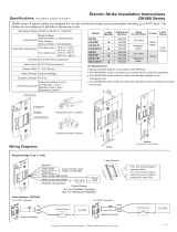
Electric Strikes Installation Instructions
Operating Voltage: 12 or 24 VDC
Voltage Tolerance: ±10%
Current Draw: 700mA/12VDC ; 350mA/24VDC
Operating Temperature: 14°F to 120°F (-10°C~+49°C)
Humidity: 0~85% non-condensing
Solenoid Testing: Over 250,000 cycles
Preload: Up to 200 lbs
Static Strength: 1,200 lbs (GK140 Series) 1,000 lbs (GK145 Series)
Construction: Stainless steel
Net Weight: 673g
Latch Throw: GK140: 15 mm, GK145: 11 mm
(With 3mm door gap)
Keeper Width: 48mm
Lock Mode: Fail-secure
GK140/145 Series
GK145
186
25
39.5
200
3
48
170
12
186
25
39.5
141
200
3
48
141
Attention!
Please follow the sticker’s
instruction to install the strike.
GK140
186
25
39.5
200
3
48
170
12
186
25
39.5
200
3
48
141
141
Unit: mm
Keeper Adjustment (GK145 Only)
Specifications
Models (M: Door Status Monitor)
DIN left DIN right
GK140-L-12
GK140M-L-24 GK145M-L-24 GK140M-R-24
GK140M-L-12
GK140-L-24
GK145-L-12
GK145M-L-12
GK145-L-24
GK140-R-12
GK140M-R-12
GK140-R-24
GK145-R-12
GK145M-R-12
GK145-R-24
GK145M-R-24
The strike keeper can be adjusted horizontally to account for various installation
anomalies. To adjust the keeper, loosen the adjustment screws, move the keeper
horizontally as needed, and retighten the adjustment screws.
(Maximum adjustable range: 3mm)
Adjustment
Screws
Strike
Keeper
Adjustment
Screws
Strike
Keeper
Door handing is determined from the side of the door where
the hinges are visible, according to the German standard DIN
107.
Stand facing the door on the hinge / pull side. If the hinge is on the
right, the door is considered to be DIN right. If the hinge is on the
left, then the door is considered to be DIN left.
DIN left DIN right
DIN left DIN right
Copyright © All Rights Reserved. P-MU-GK140 Published: 2021.08.18
Wiring Diagram
'RRUVWDWXVRXWSXW9$&
+
-
N.O.1
C.1
N.C.1
+
-
3RZHU
,QSXW
1&FRQWDFWRXWSXWFORVHGVWDWXV
12FRQWDFWRXWSXWRSHQVWDWXV
2SHUDWLQJ
9ROWDJH
'RRU6WDWXV
2XWSXW
GK145GK140
Wooden Frame
Lip extension brackets are available for wider jambs.
I
ns
wing
LP-GK231-50
50mm
LP-GK231-25
25mm
Optional Brackets Mortise Mount in Wooden Frame
132
4
Tighten the indicated screws. Connect the wires and install the strike.
Mark the position of the latch bolt on
the door frame as shown in the figure.
It must be ensured that there is a small space between the latch bolt and actuated latch stop when the door is closed
and the latch bolt is in its locked position. This will relive pressure on the solenoid valve and reduce the risk of failure
when opening the door.
Note
Measure the vertical and horizontal
position of the latch bolt on the door
leaf.
Mount the supplied template and align
to the marked line.
Drill and cut the frame according to
the template.
23.5mm
56
Installation Steps
/