Wonderfire 9500260 Installation Instructions Manual
- Category
- Fireplaces
- Type
- Installation Instructions Manual
This manual is also suitable for

Senator/Liberty
INSET LIVE
FUEL-EFFECT APPLIANCES
MODELS
NATURAL
GAS
9500260
PROPANE
9500261
Manufactured by
Wonderfire.
Copyright
C
Wonderfire
1997.
I NSTALLATION
I NSTRU
CTIONS
(Please
leave
with
the
User)
These instructions have
been
writlen
to ensure the
proper
installation
of this
fire.
Please
read
lhem carefully betore attempting to installlhe fire.
9860269 lssue 1

Dear Installer,
As
CORGI
reglstered
Installerc
ounselves,
we know
how much a
stralghtfonvard
installation
means
to
you,
so
we'ye
trled
hard
to
make
these
Instructlons
simple to follow
and easy to understand,
whllst
at the
same tlme
remalning
sufflclently comprehenslve
to
help
ensure
you
Gan
get
the
lob
done.
lf
you
encountor any
problems
that
these
Instructlons
don't
help
you
to
correct,
then
pfease
call us
on 0117
gU
12,
,
and ask
tor
the
Technlcal
Servle
Manager.
And
lf
you
have
any suggestlons
how we
oan make
your
lob
easler In
the
future
please
let me know.
Technlcal
Dlrector
CONTENTS
IMPORTANT NOTES
RELATED DOCUMENTS
TECHNICAL
SPECIFICATIONS
CONTENTS
OF
PACKAGING
PREPARATION
OF
FIREPLACE
PREPARATION
OF
APPLIANCE
GAS SU
PPLY
CONT.I€CTION
ASSEMBLY
OF
FUEL.BED
INSTALLING
THE
GI-ASS
PANEL
OPERATION OFTHE
FIRE
SPILLAGE
TEST
INSTALLING
THE
FACIA
CONSUMER
BRIEFING
SERVICING
INSTRUCTIONS
REMOVAL
OFCOMPONENTS
SPARE
PARTS
INDEX
Page
1
Page 1
Page 2
Page 4
Page
5
Page
6
PageS
Page
9
Page 11
Page 12
Page 14
Page 15
Page 16
Page 16
Page 18
Page 19
Page 20

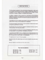
IMPORTANT
NOTES
The
Gas Safety
(lnstallation
& Use)
(Amendment)
Regulations
1990 require
that
no
person
shallcarry
out any
work
in relation
to a
gas
fitting
unless he is
competent
to do
so. CORGI
is
the
body approved
by the
Health
& Salety
Executive
to
maintain
a
register
of
competent
Gas
Installers.
In
addition, installation
must
be carried
out in
accordance
with
the
Buitding
Regulations
issued
by
the
Department
of the Environment
and the Building
Standards Regulations
issued
bythe Scottish Development
Department,
and
with
these
instructions.
lf
the
appliance
is
to be
installed
using a masonry
chimney
previously
used
for
solid fuel
the
chimney
must
be swept
prior
to
installation.
The
minimum height
of the chimney
or
flue
must
be 3m
(1Oft)
from
the
hearth
to the
point
of termination
of the
flue.
The
chimney or
flue
must have
any damper
or
restrictor removed,
or
perma-
nently
secured in
the
fully
open
position.
It is
recommended
that a
fireguard
complying with
8S6539
or
856778
be
fitted
for
the
protection
of
young
children, the elderly,
or the
infirm.
f n
accordance with
8S5871 Parl2,vsntilation
is not normally required forthis
appliance. However,
any r.equirement
relating
to other appliances which may
be
in
the same
room
must
be
taken into
consideration.
This
appliance
is for
use on the
gas
supplied.
Note
that certain
soft wallcoverings
such
as
vinyl materials
may
stain when
heated.
Must
be
installed
in
accordance with
the rules
in
force.
RELATED
DOCUMENTS
BS
5440 Part1, 1990
BS
5440
Parl2,1989
BS 715,
19g6
BS
6461
Part2,1984
BS
5871
Part 2,1990
BS 1251,1987
BS
6461
Part 1, 1984
Poge I

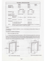
Tecnucal
SpecrncRnorus
Height Width Depth
Dimensions
670mm 635mm
320mm
Opening
Min
560mm
406mm
requlreo
Max
575mm
460mm
Natural
Gas
Propane
kW/hr
BThU/hr
kWhr BThU/h
Heat f nput Max 6.8
23,200
6.2
21,150
Min
3.2
10.900
3.6
12.250
Supply
Pressure
(G20)
20 mbar
(G31)
37mbar
Setting
Pressure
(cold)
Main
burner
Maximum
17.5
mbar
(+/-1
mbar)
35.5
mbar
(+/-1
mbar)
Injectors
Main
burner Cat
82-440
Cat
92-190
Clearances
To
combustible side
panels
100mm
(4")
To
combustible
shelves
200mm
(8")
NOTE-
Shelves over
150mm
(6")
deep
will require
an additional
25mm
(1")
in
clearance,
for
every additional
25mm
(1")
depth over
150mm.
Location
This
appliance
is not
suitable
for installation
in
a
room
or
internal
space containing
a bath or shower, or
in
a
private garage.
This
appliance is
suitable
for
the
following:-
1
Minimum flue height
of 3m
(1Oft)
2 A masonry
chimney
with
a
minimum
diameter of
175mm
(7")
free from
any obstruction, and with
any
damper or
restrictor
plate
in
the chimney
removed
or secured. A masonry
chimney
having
a correctly instailed
flexiblefluelinertoBSTI5andwithaminimumdiameterof 125mm(5")isalsoacceptable.
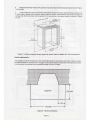
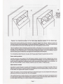
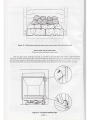
Checkthattherelevant
flatsurfacearea
is
available-seefiguresbelow.
Notethattheremaybeaneedtolocallyremovethefireplace
materials
to ensure the outer case can easilv be
installed.
700
MrN
FLAT
SURFACE
f
I
I
I
700
MtN
T
SURFACE
I
I
L
xs3$'^
1
560 MrN
575 MAX
Fig 1A. With
chairbrick
removed
Page
2
Fig 1B.
With
chairbrick
in
place

3
Firebrick
(chairbrick)
removalwill
usually
be
required
unless the dimensionsal
requirements
in Figure
1
can
be met.
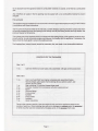
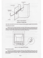
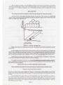
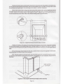
4 A
sheet
metalflue
system
conforming
with
854543
or
BS715,
the flue
diameter
being
a minimum
of
5"
(see
Figure
2
below)
with
a
minimum
internal
depth
of 250mm.
Incombustible
mineralwool
insulation
of
not less
than 50mm thickness
must
be applied
to the top
surface
of the
system
lirebox,
as
shown in
Figure
2
below.
:::::l-\
ii:l I
'i'il I
:i'i,ll
.:':.1
|
....'t
I
ili;il
sob
r'rrr'r
':;:;:l
575
MAX
:::::ill
i:i:i:ll
9l
\l
\
(-
SoMlN
INSULA1ON
I v-l-
tr#
u- l- llt
tt-
-,:_)
-- | ,-4
.AT
SUN
ffi
l.-x
*:a
J::Fi
:t::t:l
:t:jti1
l::i:l
ii:i:l
i:i:
j
f:itil
'r:'l'l
.''.t.1
t:iti1
.:.i:i
:r:.il
:t:.:.t
:i:i:j
>>-
eg
\trq
r
L---l?llii*
Figure
2
-
Selkirk
recessed
factory-made
flue
system
(Part
No
04905) & 5"
flue arrangement
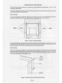
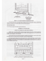
Hearth
requlrements
The
appliance must
be
mounted
on
a
non-combustible
hearth in
accordance
with Figure
3 below,
being
a
minimum
thickness
of
12.5mm
(112").
The
upper surface
of the
hearth
must
be
50mm
(2")
above floor level,
or
alternatively,
be
provided
with
an
upstanding
edge
of SOmm
in
height.
300
M
I
I
,Oaaaaaaaa
oaaaaaaaaa
aaaaaaaaaa
arooaaaaaa
aoaaaaaraa
,aaaaaaaaaa
aaoooaaaaa
aaaaaaaaaa
laaaaaaaaa
aaoaaaaaaa
aoaaaaaaa
aaaaaaoaaa
aaaaaaaaa
aaotaaaaaa
aooaoaaaa
aaaaaaaaaa
o a o a a a a
a
a
a/
,aaaaaaoaoa
aaaaaaaaoot
a a a a a a a a a at
aaaoraaaat
I o a a a a
a
o a
al
aaaaaaaaaa
a o a a a a o a a ar
a
a
a
a
ft
a
al
a
a
a
a
a
a
a
a
a
a
a
oa
aa
aa
aa
aa
aa
aa
aa
aa
aa
a
a
a
a
a
a
a
a
a
a
aooaa
aaaaoa
aaoaa
aaoaao
aaaaa
aa
a
aa
a
aa
a
a
a
a
a
a
?.
aaaaaaaal
aoaaaaoa
otaaaaoaa
aaootaoa
aaataaal
aoaoaaot
aaoaaoaa
aaoaaaa
aaaaaaaa
aaaaaaa
aaaaatta
aaaaaaa
aaaaaato
aaaaoaoa
aaaaaoto
aaaaoaat
aaaaaaaa
aaaaaaa
loaaaoaa
aoaooao
aaoaaata
ooaaaaa
aaaaaaaa
aooooaao
aaaa
aaaa
aaaa
aaaa
aaaa
aaaa
aaaa
aaoa
aaaa
aaaa
aaaa
,a a a a
Daaa
laaaa
\t.t.t.
Daa
la a a
Lt.t.
la a
aaa
ta a
Daa
lN.
I
t15o*l
-700Mrir.
Figure
3
-
Hearth
dimensions
Poge
3

On
no
account must
the appliance stand
on
combustible materials
or carpets, or be
fitted
to a combustible
wall.
Any
underfloor
air supply
in
the fire
opening
must
be sealed
with
a
non-combustible
materialto
prevent
draughts.
Fire
surround
Thisappliancemaybeinstalledwith
asurroundwitha
minimum
approvedtemperature
ratingof 150"C
if
fitted
in
accordance with
these
instructions.
The fire
sunound must
be sealed to the
wall
and a suitable fireplace
opening should be constructed
which
will
provide
a sealed
joint
from
the opening to the
flueway
with
allloints being smooth and fully sealed.
See
previous
Figures for
dimensions.
The
surface
area ol the
lireplace which
is in
contact
with
the sealing
flange
of the appliance
must
be clean,
smooth and
flat,
in
order to
provide
a
proper
seal
between
the
fireplace
and the appliance.
ll necessary, the
laces
should be
made
good
to ensure the sealing
process.
The fireplace floor
(internal
hearlh)
should be
reasonably flat,
and
made
of
non-combustible materials.
CONTENTS
OF THE PACKAGES
Borlof2
1
no.
Cast-iron
firefront
(or
outer-case),
fully
assembled,
with
gas
control access door.
Box2of2
1 no.
Inset Live Fuel-Effect
heat
engine
comprising fully assembled
firebox
heat
exchanger,
glass panel,
flame
sensing device,
ignition
system, and
ceramic burner system.
1 no
Bag
containing
14 individualshaped
dress coals
2 no.
Porcelain
moulded fronl
coal-pieces
with
pilot-viewing
cut-out
1
no.
Matrix
4 no.
Fibre wallplugs
4 no.
Fixing
screws
4 no.
Eyebolts
2
no.
Fixing
cables
2 no.
Adjusters
1 no.
Users
lnstructions
Remove
the
contents carefully. Note
the
weight
of each
part
of the appliance stated on the
outside
of each box. When handling
take care
not
to damage any
ceramic
parts,
the
enameled
or other
any
other cast-iron components,
the
glass panel,
or the
pg;9€lain
front
coals.
Page
4

PREPARATION
OF
THE FIREPI.ACE
Ensure
that the
fireplace conforms to
the
previously
stated dimensional
requirements,
or
carry
out
any
necessary
remedial work.
Decideuponthepreferred methodof retentionof
the appliance
(screworcable)and
if necessaryconsultwith
the
consumer before commencing
work.
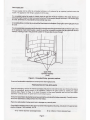
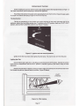
Screw retention
Four
screws and
fibre wall
plugs
are supplied
for
this
retention method, to
be
located
directly through the
appliance
sealing
flange
and
into the
vertical
plane
of the
fireplace.
(See
Figure
4
below)
Figure 4
-
Screw or Cable
retention
Ensure
all
the
fireplace
components are sufficiently
sound to take the
wall
plugs.
Drill and
plug
as
required,
carefully fitting
only the
wall
plugs
at this stage.
lf
this
method cannot be undertaken
without
damage
to the
fireplace materials,
then the use of
retaining cables
(betow)
should be
chosen.
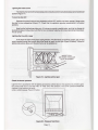
Cable retention
Cables
and eyebolts are
supplied as
an
alternative
method
of
relention. Ensure that the
internalfireplace
components
are sutficiently
sound to take the eyebotts and
wall
plugs.
These should be
fitted
in accordance
with Figure
5 below,
using the
watlplugs
and a
No. 10
drill. Use
only the
libre wall
plugs
supplied
(or
similar),
on no
account should
plastic
wallplugs
be used.
FIBRE
RAWLPLUG
SCREWED
EYELET
CABLE
NIPPLED
CABLE END
Figure
5
-
Cable
retention method & eyebolt detail
Poge
5

Gas
supply
pipe
The
gas
supply
can
be
eilher
by concealed
entrance,
or if
preferred
by
an exposed method
across
the
hearth.
The
appliance inlet
fitting
is
suitabte for
Bmm
pipe.
lf
a
concealed
method
of
supply is
chosen,
then
the
gas pipe
must
be
instalted
at this
stage, leaving
an
adequate
length
of
pipe
for
later
connection
to
the
fire.bn
no
account
should more
than 1.5ri
of
Amm
iife
be
used,
othenrise
an unacceptable
pressure-drop
may
occur.
An isolating
elbow
or similar
device
should
be
fitted
close
to
the fireplace.
Only
rigid
or semi-rigid
pipe
should
be used.
The
conce.aled
pipe
connection
can
be brought
in
through
one
of the
grommeted
holes
to the left,
right
or
rear
of the
appliance
sheet.metal
housing.
Leave
the
grommet
in
positiJn
to
protect
the
gas
pipelouier
shroud
interface,
making
a hole
in
the
grommet
suitable for
the
gas
iipe
to
pasi
through.
GAS PIPE
ENTRY
POINTS
(3
off)
Figure
6
-
Conceated
firlng
.
gas
entry
opilons
Ensure
allcombustible
materials
are
removed
from
the fireplace
area.
PREPARATION
OF
THE
APPLIANCE
Open the
packaging,
remove
the internal
packaging
and
place
to one
side for later
use. Remove
the
sleeve
from
the
packaging,
giving
access
to
the
appliance.
Remove
the
glass
panel
by rotating
the upper
retaining
clips
(Figure
16 Page
11)
to
clear
the
panel.
Lift
the
panel
upwaids
and out trom
the tirebox
assembly.
Carefully
place
the
panelwhere
it
will remain
secure.
The.burnerassembly
is retained
bytwo
screws
set
intotheverlicals
of
thefirebox
assembly.
Carefully remove
the burner
assembly
by sliding fonrard
from
the firebox.
Place
in
a safe
position,
being
carefulnot
to
damage
any ceramic
parts.
Check
the
flue
restrictor
plate
on the
upper-rear
sheet metal
apptiance housing,
and
adjust
to the
appropriate
position
(Figures
7
& 8 overleaf),
A
or B.
'A'for
175mm
diameter
(and
larger)
llues
Page
6
'B'
for 125mm-174mm
diameter flues

@
BEND
THIS
TAG
BACK
FOR
FLUES
LESS
THAN
175
DlA.
(as
shown)
Flgures 7
& 8
-
Restrlclor
positlon
"A"
for 175mm fluss, Restrlctor
posltlon
"8"
for 125mm flues
Note
that the correct
positioning
of this
restrictor is important
(Figures
7
& 8 above).
Failure to
position
the
restrictorcorrec'tlycould
cause
spillage, orreducethe efficiencyof the
appliance. Checkthatthe
sealing
rope
is
correctly
fitted
onto the
rope retaining
tags
at the
rear
of
the appliance
sealing
flange.
Take
the cardboard
internalpackaging mentioned
earlier, and
place
it flat
on the
hearth to
protect
against
damage.
Placethe
appliance onthecardboard
where marked,
and offer
it
uptothe
fireplaceopening
-
sliding
the appliance and cardboard together. Carefully
lifting
the appliarrce
slightly,
remove
the cardboard.
Ensure
that the sealing
rope willeffectively
sealagainst
the
verticalplane
of the
lireplace.
lf
a concealed
gas pipe
lixing is
to
be
used, offer the
gas pipe
through the
appropriate
grommet.
Screw
retalnlng
method
Carefully
manoeuvre
the appliance
into
the
fireplace
opening,
remove allof the cardboard
pad,
and
fix
through the
appliance
sealing
flange
to the
vertical
plane
of the
fireplace,
using the screws
supplied.
Take
care to ensure the appliance
is secured
evenly
in
orderto
provde
an effective
seal.
Do
not
overtighten,
as
this may cause damage to certain
fireplace
materials,
such as
marble
or conglomerates.
Cable
retentlon method
Assemble
the
cable through the
eyelets and
lit
adjusters
in
accordance
with
Figure
9 overleaf.
With
the
adjusters screwed-in fully,
carefully
manoeuvre
the appliance
into
the
fireplace
opening.
Take
up any slack
on the cables,
and tighten cable
nipples
into
position.
Tighten
the appliance
into
the
fireplace
opening by
turning
the
adjuster
nuts to compress the
sealing
rope
sufficiently to
provide
an
effective seal.
Do not
overtighten.
lf the sealing
rope
does
not fully
compress, then the
adjusters and
nipples
may require to be slackened,
and
the cable
pulled
up
tighter before
retightening
the adjuster.
Do not
cut
off any excess
cable,
instead
coil up
the cable
against
the
flange,
as
it
may be
required for
servicing
purposes.
PogeT

ADJUSTER
SCREWED
NIPPLE
ADJUSTER
NUT
CABLE
Figure
9
-
Cable adjustment
GAS SUPPLY CONNECTION
Note:
Before making
the
f
inal
connection
to the
gas
inlet fitting,
purge
the supply of
all air and debris.
Concealed
gas
connection
Replace
the burner assembly
into
position
in
the
firebox, without refitting the
retaining
screws at this
stage. Cut and
shape
the
gas
supply
pipe
to suit
the chosen
direction of
entry and the
gas
inlet
fitting
position.
Note
that the inlet fitting
elbow can be
loosened
and swivelled to allow
for left-
or
right-hand
gas
connection.
See
Figure 10,
below.
Refit
and tighten the burner assembly
retaining
screws.
Exposed
gas
connection
Replace
the burner assembly into
position
in
the
firebox,
wilhout refitting
the
retaining
screws at this
stage.
Using 8mm diameter
rigid
or semi-rigid
pipe,
run the
pipe
from
the
gas
inlet fitting
to a supply
restrictor
elbow or similar
adjacent to the
f ireplace.
Figure 1 1
(overleaf)
shows
alternative supply
routes
for left
or
right-
hand
connection.
Figure 10
-
Left
or
Right-hand
connection
Page
8

ALTERNATIVE
LEFT
HAND
SUPPLY
8mm
SUPPLY
PIPE
FIT TIGHT
ALONG
BOTTOM
EDGE
OF FI.ANGE
Figure 11
-
LH
or
RH
connection of exposed
gas
supply
Note
that the
pipe
must
exit the appliance through the
slot
in
the outer case column,
or beneath
the
fender,
and should be
routed
accordingly.
Refit
and tighten
the burner assembly
retaining
screws.
Note:
ensure
the control
knob is
centrally
located within
the data badge
plate.
Gas soundness
check
Turn
on the
gas
supply and
conduct a
gas
soundness test.
ASSEMBLY
OF
THE FUEL-BED
HANDLE
ALL
CERAMIC FUEL-BED PARTS TENDERLY
Senator
uses
a fuel-bed assembly which has
been
proven
in more
than
100,000
applications
throughout
the
world. Allthe
ceramic
parts
are
safe to
handle,
and
are designed
to be
easily
replaced
by the
installer,
service
engineer,
or the consumer.
This fire
uses
a
pair
of
hard
ceramic
(porcelain)
moulded front
coals
(Figure
12
below)
which
should
be handled
with
care.
Viewing
from
the
front
there
is
a cut-out for
pilot
viewing.
Each
piece
should
be
placed
into its
correct
position
in
lurn,
with
the'coal'shapes
facing
lhe
installer,
locating
the
two
retaining
lugs into
the rectangular
slots
in
the front
edge of the burner as shown
in Figure
12
below.
Gently
push
downwards
untilthe coal
pieces
are
located
securely, and the
slotted area on their
lower
surlace
touches
the burner
base.
Figure
12
-
Placing
the
front
coal and
moulded matrix.
The
matrix must
be
located fully
against the rear
of
the firebox
,c^b_.Ei-
A
,i{
tfl,
\1
t\
.7.
\
,r-\
(_-
/-
.\
r5
,J\
W
t
.r\.r.'1'
)[','*:\
Poge
9

I
I
t
Place
the
moulded
coal
matrix
(Figure
12
previous page)
on
the upper surface
of
the burner and
locate
it fully
against the
rear
of the
firebox in
a central
location.
Take five
(5)
dress
coals
from
the
bag of
fourteen
(14), placing
them so
that
the most
realistic
surfaces
may
be
seen
from
the
front
of the
fire,
and ensuring
they
bridge
the space between
the
moulded
front
coal
pieces
and
the
front
edge of the
matrix,
as
shown
in Figures
13
&
14
below
Figure
13
-
Placing
the
first five
dress coats
A random, realistic,
effect
may
be
made
as
it is not necessary
that the shapes are all
positioned
in
the
same
manner,
although
the
coals
should be
generally
equally
spaced
for the
best
flame
effect.
Take
care
not
to allow any
part
of the
five
dress coals to
locate
between
the
rear
of the
front
coal
pieces
and
the
vertical
serrated surface at
the
front
of
the
burner.The correct
position
is
shown
in Figure 14
below.
FRONT
COALS
VIEW TO
SHOW
BRIDGING
Figure 14
-
Bridging
the
front
coals and matrix with
6
dress coals
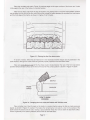
Place
a
further
row
of
five
(5)
coals on the
matrix in
a
random fashion
above the
first
six coals
previously
placed,
as shown
in Figure 15
overleaf.
Then
place
the
remaining four
(4)
coals
in
a
row
on
the surface of the
matrix
above the second
row
of coals,
leaving
a
space between
these two
rows
to allow the best
flame
effect.
Ensure
a
generally
even spacing between all
the
coals
for the
best effect.
i;;
f
. it
--
\tl
,-
z.
ril
-/
1r',
f.
V.
*
iY .:'1 U
i"
\i
,l
|}
i
i'
t',1-'^
*
)lr
.l:
illit
l'
*:J
,'^
t I
fA
tA,^
'
?u,.,n! d_a(
Page
10

Figure
15
-
Placing
the
remaining
dress coals
in
two
rows
of
five
(5)
and
four
(4)
INSTALLING
THE GLASS PANEL
Take
care
when handling
the
glass panel
Take
the
glass
frame
assembly and offer
up centrally
to the
fabricated
steel
firebox.
Insert
the
lower
corners of the
frame
assembly
into
the U channel
locations
on
the
firebox. Line
up
the upper
location
points
and
with the thumb
screws
provided
tighten the upper section of
the
glass
assembly
onto
the
firebox.
To
ensure
a
tight seal
is
achieved, the use of a
flat headed
screwdriver
will
be
required
in
order
to bed
down a
new
seal.
Figure 16
-
The
glass
retaining clips
Poge
1 I

OPERATION OF THE FIRE
Before
installing
the cast-iron firefront
(outer
case)
please
observe the
lmportant Notes
on
Page
1
of
the Users Instructions,
before attempting
to
operate
this appliance.
Read
these
instructions
thoroughly
before operating
the
fire forthe first
time. Ensure
the
gas
supply
is
purged
of air before attempting
to
light
the
fire for
the
first
time.
The
Gas
Control
This
fire is
controlled by
a
four-position
gas
control mounted
on the
lower right-hand
side of the
appliance,
behind the flush-fitting
access
door.
In
addition to the
OFF
position,
there
is
a
PILOT
LIGHT
position,
and two
HEAT
CONTROL
positions
(see
Figure 17
below).
Figure 17
-
lgnition
and
heat
control
posltlons
lgnition
of the
fire is
by
piezo
which ignites
the
pilot
flame. The main
burner
is lit from
this
pilot.
Lighting
the
Pllot
Ensure
that
the
gas
supply
is
on.
Turn
the
gas
control
knob
to the OFF
posilion.
Depress
the control
knob
and turn anticlockwise
until the
PILOT
position
is
reached. lgnite
the
pilot
flame. Keep
the
knob
depressed.
Observe the
pilot
flame is
alight by
viewing
the
lower
edge of the
fuel-bed
on the
left-hand
side of the
fire,
through
the cast
iron fretwork
above the
fender.
(Figure
18
below).
PILOT
VIEWING
Page 12

Lighting
the
main
burner
The main
burner
can
be
lit
by depressing and turning the control
knob
anticlockwise to the
MAXIMUM
position
(Figure
17)
To
turn the
fire
OFF
Depress
the control
knob
and
turn clockwise untilthe
OFF
position
has
been
reached.
Observe that
the
pilot
is now
extinguished
(Figure
17).
Check that the
appliance operates satisfactorily
in
all control
positions.
Note
that the
fuel-bed may
take up
to
15 minutes
to
provide
a
realistic
glow,
and
that the
flames
will
be
predominately
of a blue colour untilthe
fire has
completely
heated
up
to
its
usual operating temperalure.
This is
normal.
Lighting
the
fire with
a taper
ln
the event of
failure
of the
piezo
spark
generator,
the
pilot
flame
can be
lit
by a taper, spill, or
long
match inserted
through the
fretwork
above the
fender
to
reach
the
pilot
light
(Figure
19
below).
Follow
the
lighting
instructions
above untilthe
pilot
flame
can
be
established.
INSERT SPILL
OR
TAPER
THROUGH
SLOT
IN FENDER
Check the burner
pressure
Light
the
fire in
accordance
with
the
lighting
procedures
outlined above.
The
appliance
is
pre-set
to
give
the correct
heat input
at
20 mbar NG.; 37 mbar LPG.
inlet
pressure.
The
burner
pressure
should
be
checked at
the
pressure
test
point,
using a
suitable
gauge (Figure
20
below).
Figure
20
-
Pressure Test Polnt
Poge 13
Figure 19
-
Lighting with
a taper

With
the
appliance operating
in
the
MAXIMUM
position
the
burner
pressure
should be
in
accordance
with Technical
Specifications,
Page 2. After
checking the
pressure,
turn off the appliance and
replace
the test
point
sealing screw.
Relight
the appliance, turn to
MAXIMUM,
and
test
around
the sealing screw
for
gas
soundness.
SPTLLAGE
TEST
This
spillage
test
must
be conducted to
confirm the safe clearance
of combustion
products.
Light
the
fire if it is not
already operating,
and allow to
warm
up
for five minutes
at the
MAXIMUM
position.
Place
a smoke
match into
the spillage
sensing tube
(Figure
21
below)
so
as the
whole head
of the
match is
at
least 12mm inside
the tube.
MATCH
HEAD
12mm
INTOTUBE
Figure 21
-
Conduct
a Spillage
Test
Observe
the smoke,
if it is
drawn
into
the tube then the appliance
is
clearing the combustion
products
satisfactorily
lf
smoke
expels
from
the tube
then
allow the appliance to
warm
up
for
a
further
ten
(10)
minutes
and
repeat
the
test.
lf
spillage occurs
remove
the appliance
from
the
fireplace
opening, and
adjust the
flue
outlet
restrictormountedonthe
rearof
thefirebox
(See
Figures 7and8
PageT)tothefullyopenpositionfor5"flues,
allow to
warm
up and
repeat
the test.
lf
spillage continues to occur,
do not
proceed.
Seek
expert advice.
Additionally,
if
an extractor
fan is fitted in
the same
-
or
a
communicating
-
room
space,
a check should
be carried
out
with
doors and
windows
closed and the
fan
tumed on.
lf
the
appliance continues to spill, the cause
must be rectified
before
proceeding
with the installation.
Before
undertaking
the
following
procedures,
ensure that the
fire has
been
previously
switched
off
,
and
has
been allowed to coolcompletely.
INSTALL|NG THE
CAST-|RON FTREFRONT
(OUTER
CASE)
Please
read these
instructions fully
before attempting to install the firefront for the
first
iime.
THE
CAST IRON FIREFRONT IS HEAVY
The
cast-iron firefront
(outer
case) supplied with
Senator
is
a
high
quality
casting weighing around 28kgs
(60lbs).
lf
you
have
any doubt of
your
ability to easily lift
or
remove
this
component,
you
should ask someone
to assist.
Like
the
Senator the Liberty weighs
around 28
kgs
(60lbs).
lf
you
have
any doubt
of
your
ability to
easily
lift
or remove
this
component,
you
should
ask someone
to assist. Due to the
curved
nature
of
the
case design Liberty requires
careful
lifting
onto the heat
engine,
if
you
utilise
the
convection
air
or
fender
apertures for lifting
be careful not to
pass
your
fingers
through the apertures
due
the
possibilty
of
pinching
when
offering
up to the
engine.
Page 14

Assistancewillalso help
avoid damagetothe
tirefrontcomponent
itself
,
the
painted
orenameled
finish,
the
fire
surround and
fireplace components, and
will
avoid
possible
injury
to
yourself
. You may
wish
to utilise
the cardboard
packaging
again, to
avoid damge to the
hearth or
firefront
component.
Note
the
the
firefront has
two
lugs
cast
into
the
rear
of the
mantle shelf, and lwo steel
lugs attached
to
lhe
rear
of each
vertical column
which locate
into
the slots
in
the sheet
metal. Carefully
lift
the
firefront into
a
position
square to the sealing
flange of the appliance, some
1"
(25mm)
above and away
from
the
four
location
slots
formed in
the sheet
metal
of the chassis sealing
frame
(Figure
22
below).
Figure
22
-
Install
the
firefront into the slots
provided
Holding the
firefront
a
little above the top
surface of the chassis
sealing
flange,
locate the
fixing lugs
into
the slots
provided
in
the sealing
flange,
push
carefully
towards
the
fireplace, and
GENTLY
lower
the
component onto the
hearth
ensuring that
no damage occurs to the
f inish of the
f
acia, or
to the
hearth
material
itself.
All four fixing
lugs
should
locate into the slots, and the
firefront
should
sit squarely
on
the
hearth,
locating
against the
vertical
surface
of the
fireplace.
Note: lf
thegas
supply
is
across the
hearth,
ensurethatthe
supply
pipe
is located through
the
purpose-
provided
slot
in
the
firefront
casting.(Figure
23 below).
The installation
is now
complete,
please
brief the
consumer.
GAS
SUPPLY
CUT-OUT
\rrrr."
Figure
23
-
Ensuring an exposed
gas
supply
enters
correctly
Poge lS

CONSUMER
BRIEFING
Once the
appliance
has
been
fully
installed
and commissioned,
instruct
the User on
its
correct
operation.
The
cleaning
procedures
recommended
in
the Users
Instructions
should be
explained
in
detail, and
coal
placement
explained.
The
consumer must
be
warned
not
to
vary
the
coal
layout,
and of the dangers of
adding extra
@als, or of operating
the appliance
without
the
glass panel
in
place.
Explain how
the
firefront may
be
removed
and
refitted,
and
suggest that the elderly or
infirm request
assistance
in
the event the
firelront requires
renpval.
Inform
the
consumer that any servicing
is
to
be
carried
ofi by a CORGI
installer.
These Instructions
should
be
left with
the consumer.
Explain
that the
appliance
is fitted with
an
A.S.D.
(Atmosphere
Sensing
Device).
lf
the
appliance
closes down after
a
period
of operation
for
no
apparent
reason,
the consumer should be
informed
to
stop using
the
appliance,
until the
installation
and appliance
have
been
thoroughly checked.
SERVICING
INSTRUCTIONS
Glass
Panel
Occasional
cleaning of the
inside
of the
glass panel
may
be
required
between services.
Instruclions
for
this
procedure
are contained
in
the Users
Instruclions.
Regular
Servicing
Allow
the
appliance to
cool
completely
if
it
has
been operating.
lsolate
the
gas
supply to the
appliance
prior
to
commencing
work.
HANDLE ALL
CERAMIC
FUEL.BED
COMPONENTS
TENDERLY
Senator uses a
fuel-bed assembly
which has
been
proven
in more
lhan
100,000
applications
throughout
the
world. Allthe
ceramic
parts
are safe
to
handle,
and are designed to be
easily
replaced
by the
installer,
serviceman,
or consumer.
The
fourteen
(14)
individual
dress coals
(Figure
15 Page 1'1)
should be
removed,
noting
their
approximate
positions
to
facilitate replacement,
and then
placed
on a
piece
of
newspaper. Any
deposits can
be carefully
removed from
the surface of the coals
using a soft brush
(such
as a
paint
brush).
The
two
parts
of the
porcelain
ceramic
front
coals
(Figure
12 Page
9) and the
moulded
ceramic coal
matrix
(Figu
re
1 2 Page
9)
should
now
be
removed from
the
burner surface,
noting
their
positions
and
location
to simplify replacement.
They may
be cleaned
with
a soft
brush.
The
burner surface,
three
flue
outlet
ports
and
firebox
surfaces
may
be
CAREFULLY cleaned by the
use
of a
vacuum-cleaner
USING ONLY A
SOFT
BRUSH ATTACHMENT.
Remove
only
loose
particles,
and
ensurethatlheburnersurface,
burnerports, and
moulded
shapes are not
inanywaydamaged
bythecleaning
actiort
Inspection
of the
burner
Disconnect
the
gas
supply
from
the
gas
inlet fitting
at the
front
of the burner assembly.
(Figurel
0
Page
8).
Remove
the
two burner assembly
retaining
screws,
and slide the
assembly
out of the
firebox,
taking
care
nottodamage
anyceramiccomponent.
Anydepositsordebris
should becarefullyremoved
with
a
SOFT
BRUSH.
The
burner
slots should be
inspected
to ensure they are clear
of debris, and any blockages carefully
removed.
On no
account should
tools be used
which
may
enlarge or damage the burner slots.
The
burner
surface should
be
inspected
lor
damage.
Consult the
manufacturer for
advice
if in
any
doubt
if
damage is
present.
Any
surface crazing of
the ceramic surface of the burner,
matrix,
and
fuel
components is
usual and
is no
cause
lor
concern.
Page 16

Check
the
injector and
venturi
for
linting
or
obstruction.
lf
there
is
a
need to
remove
the
injector,
please
see
Removal of Components.
Checkthe
injector
remains
aligned
correctlyto
fire
centrally
intothe
venturi.
Adjustthe
iniector
position
as
required.
Check the smooth
operation
of
the control
tap,
the
Integrily of the
gas
train, and
the
piezo
ignition
lead
and connections.
Remove
any
deposits or
debris
from
around
the
pilot
light,
and check
that the
piezo generator
is
sparking
correctly by
operating
the combined
tap and
piezo
control.
Ptace the burner
assembly
to one
side taking
care
not
to damage
the ceramic
components.
Inspect
the
flue/chimney
Remove
the
four
retaining
screws
from
the
appliance
sealing
flange
(Figure
4 Page 6) or
alternatively
slacken the cable
adjuster
and
remove
the cable
nipples,
if fitted
(Figure
5
Page 5).
Carefully
slide
the appliance
out
of the
fireplace opening,
ensuring
no damage
occurs
to the
hearth
material.
lnspect the
general
condition
of
the
flue and
remove any
deposils
or debris
from the
fireplace
opening
or
flueways.
Repairanycracking
intheflueway before
reassembling.
InspecttheconditbnoJthe
rope
sealand
also
ensure this
is
correctly
positioned
to ensure
an
effective
seal.
Ensure th€
rope seal
is fully
intact before
re-
fitting.
R+installthe
appliance
in
accordance
with
the
installations
instrudirrs
contained
herein. Care
must
be taken to ensure
the corect
appliance
sealing
and
fuel-bed
layort.
Commission
the
fire in
accordarrce
with
the
lnstallation
Instructions.
Conduct
a
gas
sotndness
test,
and
a
llue
spillage test
to
verify the safe
operation
of the
appliance
as
prwiously
described
(Page
14).
Leave
these
instruction
with
the User.
REMOVAL
OF
COMPONENTS
Removal
of the
A.S.D.
(Atmosphere Sensing
Device)
Remove
the
burner
assembly
in
accordarrce
with the
instructions
on
Page
16.
Taking
care
not
to
damage the
ceramic
components,
invert the burner
assenrbV
and disconnect
the
thermocouple
nut at the
gas
control.
Disconnect the
pilot
supply
pipe
at
the
A.S.D. end,
and
carefully
withdraw
the
Assembly.
Disconnect the electrode
lead
at
the
A.S.D. end.
Remove
the
two screws
holding the
pilot
burner
assembly
to the burner
tray.
The
pilot
assembly
may now be
removed.
Re'assemble
in
reverse order'
Poge
17

Removal
of
the
gas
control
Remove
the burner assembly
in
accordarrce
with
the
instructions
on
Page
16.
Taking
care
nol
to
damage the ceramic components,
inved
the hrmer assembly and disconnec't the
thennocouple
nut from
the
gas
control.
Disconnect the
pilot
supply
pipe
at tho
gas
control end. Disconnect
the
main
htmer supply
pipe
at the
gas
control end.
Disconnect
the
inlet
pip€
at
the
gas
control end.
Remove
the
gas
control
retaining locknut from
the
control
mounting
brackets
and
withdraw
the control.
Re-assemble in
reverse
order.
Removal
ol the maln burner Inlector
Remove
the bumer assembly
in
accordance
with
the
instrucltions
on
Page 16.
Taking
care
not to
damage
the ceramic
components,
inveil
the bumer assembly and disconnect
the
main
burnersupplypipefromthe injectorend,takingcaretosupportthetumingaaionbyretainingtheinjeclor
position
usining a
suitable spanner on the square end. Unscrew the ini€ctor.
Re-assemble in reverse
order,
ensuring
the conect alignment of the
injector firing
down the centre-
line
ol the
venturi.
Assembly
of the
FlrefronUOuter
Case
ln
the event of
damage to the Outer Case, the
individualcastings
may
be
replaced
as bllows.
Remove
the damaged Orter
Gase as
described on Pages 14115.
Dis-assemblg the
case
into
ths
five
cast components
by
removing
the
nuts hoHing
the
assembly.
Remove
the damaged component,
and
replace
the
new
one
in
position.
Carefully
replace
and tighten the
nuls without
damaging
lhe
painted/enameled
finish
by use of undue
pressure.
Re-installthe
Outer Case
following
the
instructions
on
Page 14115.
NOTE
Liberty is
a one
piece
casting with
only
the
control door
access casting being
replaceable
as an
individual
item.
Page 18
Page is loading ...
-
 1
1
-
 2
2
-
 3
3
-
 4
4
-
 5
5
-
 6
6
-
 7
7
-
 8
8
-
 9
9
-
 10
10
-
 11
11
-
 12
12
-
 13
13
-
 14
14
-
 15
15
-
 16
16
-
 17
17
-
 18
18
-
 19
19
-
 20
20
-
 21
21


Wonderfire 9500260 Installation Instructions Manual
- Category
- Fireplaces
- Type
- Installation Instructions Manual
- This manual is also suitable for
Ask a question and I''ll find the answer in the document
Finding information in a document is now easier with AI
Related papers
Other documents
-
Lopi WILMINGTON GRILLS DVL 91002190 User manual
-
Baxi Fires Division 739 Installer's Manual
-
Avaya M4648ML-T Installation guide
-
-
-
-
 Haloview BTC128 User manual
-
Casio P460 User manual
-
Jenn-Air CCG2523 Guide User manual
-
 Great Outdoors Blackstone1000 Owner's manual

