Page is loading ...

www.mellanox.com
216 Port InfiniBand FDR Switch Platform
Hardware Installation Guide
PN: MSX6512-NR, MSX6512-4R
Rev 1.0

Mellanox Technologies
350 Oakmead Parkway Suite 100
Sunnyvale, CA 94085
U.S.A.
www.mellanox.com
Tel: (408) 970-3400
Fax: (408) 970-3403
Mellanox Technologies, Ltd.
Beit Mellanox
PO Box 586 Yokneam 20692
Israel
Tel: +972 (0)4 909 7200 ;
+972 (0)74 723 7200
Fax: +972 (0)4 959 3245
© Copyright 2012.
Mellanox, Mellanox logo, BridgeX, ConnectX, CORE-Direct, InfiniBridge, InfiniHost, InfiniScale, PhyX, SwitchX, Virtual Protocol
Interconnect and Voltaire are registered trademarks of Mellanox Technologies, Ltd. FabricIT, MLNX-OS, Unbreakable-Link, UFM and
Unified Fabric Manager are trademarks of Mellanox Technologies, Ltd.
All other trademarks are property of their respective owners.
216 Port InfiniBand FDR Switch Platform Hardware Installation Guide
Document Number: 3877
Mellanox Technologies2
NOTE:
THIS HARDWARE, SOFTWARE OR TEST SUITE PRODUCT (“PRODUCT(S)”) AND ITS RELATED DOCUMENTATION ARE
PROVIDED BY MELLANOX TECHNOLOGIES “AS-IS” WITH ALL FAULTS OF ANY KIND AND SOLELY FOR THE PURPOSE
OF AIDING THE CUSTOMER IN TESTING APPLICATIONS THAT USE THE PRODUCTS IN DESIGNATED SOLUTIONS. THE
CUSTOMER'S MANUFACTURING TEST ENVIRONMENT HAS NOT MET THE STANDARDS SET BY MELLANOX
TECHNOLOGIES TO FULLY QUALIFY THE PRODUCT(S) AND/OR THE SYSTEM USING IT. THEREFORE, MELLANOX
TECHNOLOGIES CANNOT AND DOES NOT GUARANTEE OR WARRANT THAT THE PRODUCTS WILL OPERATE WITH THE
HIGHEST QUALITY. ANY EXPRESS OR IMPLIED WARRANTIES, INCLUDING, BUT NOT LIMITED TO, THE IMPLIED
WARRANTIES OF MERCHANTABILITY, FITNESS FOR A PARTICULAR PURPOSE AND NONINFRINGEMENT ARE
DISCLAIMED. IN NO EVENT SHALL MELLANOX BE LIABLE TO CUSTOMER OR ANY THIRD PARTIES FOR ANY DIRECT,
INDIRECT, SPECIAL, EXEMPLARY, OR CONSEQUENTIAL DAMAGES OF ANY KIND (INCLUDING, BUT NOT LIMITED TO,
PAYMENT FOR PROCUREMENT OF SUBSTITUTE GOODS OR SERVICES; LOSS OF USE, DATA, OR PROFITS; OR BUSINESS
INTERRUPTION) HOWEVER CAUSED AND ON ANY THEORY OF LIABILITY, WHETHER IN CONTRACT, STRICT LIABILITY,
OR TORT (INCLUDING NEGLIGENCE OR OTHERWISE) ARISING IN ANY WAY FROM THE USE OF THE PRODUCT(S) AND
RELATED DOCUMENTATION EVEN IF ADVISED OF THE POSSIBILITY OF SUCH DAMAGE.

216 Port InfiniBand FDR Switch Platform Hardware Installation Guide
Rev 1.0
Mellanox Technologies 3
Table of Contents
Chapter 1 Chassis Installation 9
1.1 Environmental and Safety Recommendations 9
1.2 Chassis Package Contents 10
1.3 Leaf Package Contents 10
1.4 Spine Package Contents 11
1.5 Management Package Contents 11
1.6 Physical Installation 11
1.6.1
ESD (ElectroStatic Discharge) Connection 11
1.6.2 Installation Procedure 12
1.7 Installing the Chassis 18
1.8 Inserting the Leafs 22
1.9 Inserting a Management Module 23
1.10 Inserting a Spine Board 24
Chapter 2 Installing the Cable Holder 25
Chapter 3 Ground Connections 28
Chapter 4 Power Connections 29
4.1 Powering Up the Switch Platform 29
Chapter 5 InfiniBand QSFP Cable Installation 31
5.1 Port Connector Interfaces 31
5.2 Supported Approved Cables 32
5.3 Cable Power Classes 32
Chapter 6 Chassis Power Up 33
6.1 Power Supply, Management Board, and Spine Board Indicator Status at Power ON 34
Chapter 7 InfiniBand Fabric Initialization and Management 35
7.1 Configuring the Switch Management Modules for the First Time 35
7.2 Rerunning the Wizard 40
Chapter 8 MLNX-OS Management Software 41
8.1 Starting an SSH Connection to the Switch 41
8.2 Starting a WebUI Connection to the Switch 41
Chapter 9 Resetting the Switch – RST 43
Chapter 10 TroubleShooting 44
10.1 Power Supply Unit 44
10.2 Leaf Board 44
10.3 Management Module 45
10.3.1 Yellow Status LED (for the Chassis) on the Management Module is Lit 45
10.3.2 Yellow LED for the Leaf Fan on the Management Module is Lit 45
10.3.3 Yellow LED for the Spine Fan on the Management Module is Lit 46
10.4 Spine Board 46
10.5 MLNX-OS Software 46

Mellanox Technologies4
Rev 1.0
List of Figures
Figure 1: Shock and Tilt Stickers 13
Figure 2: Shelf Installation Kit Parts 14
Figure 3: Inserting the Caged Nuts for the Shelf 16
Figure 4: Use These Holes for the Rail Slides 16
Figure 5: Connect Rail Slide to Rack Vertical support 17
Figure 6: Inserting the Caged Nuts for the Faceplate 17
Figure 7: Chassis Rails and Rail Slides 18
Figure 8: Screw the Handles Onto the Chassis 19
Figure 9: The Rails are Already Connected Onto the Chassis 19
Figure 10: Chassis on the Shelf 20
Figure 11: Put on the Rail Slide 21
Figure 12: Face Plate Mounting Bolt Locations 21
Figure 13: Move the Rail Slide to the Vertical Support 22
Figure 14: Ejector Latch 23
Figure 15: Ejector Latch 23
Figure 16: Spine Board Insertion 24
Figure 17: Ejector Latch 24
Figure 18: Cable Holders 25
Figure 19: Inserting the Caged Nuts for the Cable Holder 26
Figure 20: Cable Holder Placement 27
Figure 21: Ground Connection 28
Figure 22: Multiple Power Inlets - Electric Caution Notification 30
Figure 23: Spine Module 30
Figure 24: Port Numbering 32
Figure 25: Top and Bottom Ports 32
Figure 26: Spine Side Panel Display Status Indications 34
Figure 27: Management Module Status Indications for Normal Operation 34
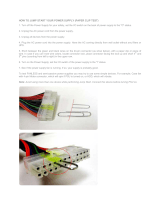
Figure 28: Connecting the Harness to the Console 35
Figure 29: Web UI Login Page 42
Figure 30: Reset Button 43

216 Port InfiniBand FDR Switch Platform Hardware Installation Guide
Rev 1.0
Mellanox Technologies 5
List of Tables
Table 1: Revision History of this User’s Manual 6
Table 2: Reference Documents and Web Sites 7
Table 3: Serial Terminal Program Configuration 36
Table 4: Configuration Wizard Session - IP Configuration by DHCP 36
Table 5: Configuration Wizard Session - IP Zeroconf Configuration 38
Table 6: Configuration Wizard Session - Static IP Configuration 39

Mellanox Technologies6
Rev 1.0
Revision History
Table 1 - Revision History of this User’s Manual
Revision Date Details
1.0 July2010 Initial release

216 Port InfiniBand FDR Switch Platform Hardware Installation Guide
Rev 1.0
Mellanox Technologies 7
About this Manual
This manual provides installation and set-up instructions for the SX6512 QSFP Chassis
InfiniBand Switch Platform.
Intended Audience
This manual is intended for users and system administrators responsible for installing and
setting up the switch platform.
The manual assumes familiarity with the InfiniBand
®
architecture specification.
Related Documentation
The documentation set accompanying the QSFP Chassis InfiniBand Switch platform
includes the following:
Table 2 - Reference Documents and Web Sites
Document Conventions
Throughout this manual, the name SX6512 and the terms chassis and switch are used to
describe the switch, unless explicitly indicated otherwise.
The following pictures are used throughout this document to indicate information that is
important to the user.
InfiniBand Architecture Specification, Vol. 1,
Release 1.2.1
The InfiniBand Architecture Specification that is provided by
IBTA
Switch Hardware Errata For any possible errata due to hardware issues see the switch
support product page. This requires a customer support login.
Mellanox MLNX-OS™ SwitchX® Software WebUI
User’s Manual
WebUI Overview for MLNX-OS software.
Mellanox MLNX-OS™ SwitchX® Software User
Manual
This document contains information regarding configuring and
managing Mellanox Technologies' SwitchX Switch Platforms.
MLNX-OS™ Software Command Reference Guide Command Reference Guide for MLNX-OS listing all of the
commands available through MLNX-OS with explanations and
examples.
MLNX-OS™ Software Configuration Guide Configuration Guide for MLNX-OS displaying different config-
uration scenarios.
This symbol makes recommendations to the user.

Mellanox Technologies8
Rev 1.0
This symbol indicates information that is helpful to the user.
This symbol indicates a situation that can potentially cause damage to hardware or
software.
WARNING! This symbol indicates a situation that can potentially cause personal
injury and / or damage to hardware or software.

216 Port InfiniBand FDR Switch Platform Hardware Installation Guide
Rev 1.0
Mellanox Technologies 9
1 Chassis Installation
Installation and initialization of the chassis is a simple process requiring attention to the
normal mechanical, power, and thermal precautions for rack-mounted equipment. Your
chassis comes only with the power supplies and fans pre-installed. The rest of the open-
ings are populated with blanks. All of the leafs, spines, and management modules come
shipped in separate packages.
The chassis requires initial configuration to get the chassis and Fabric management up and
running through remote management. see “Configuring the Switch Management Modules
for the First Time” on page 35.
1.1 Environmental and Safety Recommendations
The following are Mellanox recommendations.
This chassis can be installed in standard 19” racks that have depths between 65cm
(25.6in.) and 80cm (31.5in.) between the vertical supports of the rack.
This unit is intended for installation in a Restricted Access Location. A restricted
access area can be accessed only through the use of a special tool, lock and key, or
other means of security.
Recommended ambient temperature in the System room is 20
o
± 5
o
C.
Recommended humidity ranges is 40% ± 15% without condensing.
It is highly recommended that the installation sites be as isolated as possible from all
sources of radio transmissions and electrical interference.
It is highly recommended that the installation site building be equipped with a light-
ning rod.
It is highly recommended that the installation site be equipped with smoke detectors
and a fire alarm warning system.

Chassis Installation
Mellanox Technologies10
Rev 1.0
1.2 Chassis Package Contents
The chassis package includes:
• 1 chassis with the following modules installed:
4 fans
4 PSUs
If you are not using a mechanical lift to install the chassis,reduce the weight of the chassis by
removing all of the power supply units, and fan units, and put aside for reinstallation after the chas-
sis is installed in the rack.
• 1 installation kit
• 1 box containing 4 power cords 250v 15a 2.0M, C14 to C13, USA UL Standard
• 1 cable management kit
• 1 Installation Guide
Before you install your new SX6512 chassis, unpack the system and check to make sure that all
the parts have been sent, check this against the parts list see “Installation and Cable Management
Kit Parts” on page 12. Check the container for visible damages that may have occurred during
shipping.
1.3 Leaf Package Contents
The leafs are ordered by the customer and are shipped 4 to a box. The customer will receive as
many boxes as needed to fill the order.
The system requires a KVA rated UPS system. It is recommended that a UPS system
be installed to protect the equipment in the event of unexpected power failure.
Make sure that the outlets and circuits will not be overloaded. Spread out the load over
at least two or three circuits or use a 3 phase circuit. N+N grid redundancy requires 2
independent power supply sources.
If anything is damaged or missing, contact your customer representative immediately.
The rack mounting holes conform to the EIA-310 standard for 19-inch racks. Guaran-
tee proper ventilation, by leaving 8cm (3”) of space to the front and rear of the switch.
This will ensure proper air flow through the chassis. This is crucial for maintaining
good airflow at ambient temperature. In particular, route cables such that they do not
impede the air into or out of the chassis.

216 Port InfiniBand FDR Switch Platform Hardware Installation Guide
Rev 1.0
Mellanox Technologies 11
1.4 Spine Package Contents
The spines are shipped 3 to a box. The customer will receive as many boxes as needed to
complete a full complement of spines.
1.5 Management Package Contents
The package includes:
• all of the management modules ordered by the customer
• 1 RJ45 to DB9 harness for each management module received
If you want to hook up to a USB connector you will need to acquire a DB9 to USB
adapter.
1.6 Physical Installation
The switch platform uses 10U of rack space in a standard 19” rack, 9U for the chassis and
1U for the shelf. The switch ships from the factory with mounting holes on the spine side
only. There are upper brackets to connect the leaf side to the rack near the top of the chas-
sis. The weight of the switch is supported from underneath the unit by the shelf.
This chassis can be installed in standard 19” racks that have between 65cm (25.6in.) and
80cm (31.5in.) between the vertical supports of the rack. Make sure that a fully populated
rack including cables will have sufficient air flow for cooling.
1.6.1
ESD (ElectroStatic Discharge) Connection
Before starting any procedure on the SX6512 switch system do the following.
Step 1. Put an ESD prevention wrist strap on your wrist, and make sure there is good
contact between your body and the strap.
Step 2. Plug the other end of the wrist strap to a valid ground. Make sure that this is a
tight fit.
Warning: This equipment is very heavy. Safety is the first concern. Make sure that
proper manpower and equipment are used for transporting and moving the chassis.
The fully loaded chassis weighs:
120 kg (265 lbs) full configuration
48 KG ( 105 lbs) empty configuration
83.94kg (185lbs.) As shipped configuration
Choose a rack which is able to support the mechanical and environmental characteris-
tics of a fully populated switch chassis.

Chassis Installation
Mellanox Technologies12
Rev 1.0
1.6.2 Installation Procedure
1.6.2.1 Requirements
You will need:
1.6.2.2 Installation and Cable Management Kit Parts
Parts for installing the shelf
Parts for installing the chassis
Parts for installing the cable manager
You will need 10 U of space in the rack. Nine U for the chassis and one U for the shelf.
1.6.2.3 Container Mishandling
The container has shock and tilt stickers applied. These will turn red if the container has been mis-
handled or roughly handled. Upon receipt of the container look for and inspect the shock and tilt
stickers to confirm that they have not tripped. If one or more are red notify the shipper and Mella-
• #2 phillips screwdriver • #3 phillips screwdriver
• a grounding lug • ground wire to properly ground the chassis
The installation will be much easier with a power screwdriver.
It is recommended to use AWG6 or 4mm diameter wire for grounding purposes.
It is recommended to have at least two people for the duration of the installation proce-
dure. Use a mechanical lift to raise this chassis. If not, use enough manpower to ensure
the safety and wellbeing of all of the people involved in the installation.
• 1 shelf • 16 M6 bolts for the caged nuts 8 for the
shelf and 8 for the faceplate
• 16 caged nuts 8 for the shelf and 8 for
the faceplate
• 2 Shelf rail slides
• 2 Chassis rail slides • 4 Handles
• 8 pan head bolts • 8 Allen head screws
• 2 Flat 4 hole metal spacers • 1 allen wrench
• 8 split lock washers •
• 1 RH cable holder • 1 LH cable holder
• 8 caged nuts M6 • 8 M6 bolts

216 Port InfiniBand FDR Switch Platform Hardware Installation Guide
Rev 1.0
Mellanox Technologies 13
nox. This on its own does not indicate damage to the contents. But, be sure to carefully
inspect the contents if any of the shock and tilt stickers have tripped.
Figure 1: Shock and Tilt Stickers
HANDLEWITHCAREHANDLEWITHCARE
GGIINN NNRRWWAA
GG
II
NN NNRRWWAA
HANDLEWITHCAREHANDLEWITHCARE
GG
II
NN NNRRWWAA
GG
II
NN NNRRWWAA
TI L TWA
T
CH
TIL TWA
T
CH
Stickers unaffected by shipping
Stickers showing excessive
shock or tilt.

Chassis Installation
Mellanox Technologies14
Rev 1.0
Figure 2: Shelf Installation Kit Parts
Shelf
Rail
Rail Slide
Angled
Bracket
M6 X4 Caged nut
M6 X4 bolt

216 Port InfiniBand FDR Switch Platform Hardware Installation Guide
Rev 1.0
Mellanox Technologies 15
1.6.2.4 Opening the Container
Step 1. Check the shock and tilt stickers on the container to see if it was subjected to
excessive shock or tilting. If any of these stickers are tripped contact your
Mellanox representative.
Step 2. Before starting the procedure, put the ESD strap on and connect it to a valid
ground.
Step 3. Open the crate by opening the latches.
Step 4. Unscrew the sides of the crate.
Step 5. Remove and put aside the box containing the cables.
Step 6. Remove and put aside the box containing the cable management kit.
Step 7. Remove and put aside the box containing the Installation kit.
Step 8. Visually inspect the chassis, make sure that:
there is no visible damage
4 PSUs are installed
all 4 fans are installed
Step 9. Remove all protective plastic film from all sides and top of the chassis.
Step 10. If you are not using a mechanical lift to install the chassis, reduce the weight
of the chassis by removing all of the spines, power supply units, fan units, and
management modules, and put aside for reinstallation after the chassis is
installed in the rack.
R
L
Rail Slid
Screws for
the handles
Pan head
screws
Washer

Chassis Installation
Mellanox Technologies16
Rev 1.0
1.6.2.5 Installing the Shelf
Step 1. Place the ESD mat on the floor where you will be working and put on the ESD strap.
Make sure the ESD strap is touching your skin and that the other end is connected to a
verified ground.
Step 2. Clip 4 caged nuts into the holes in the rack you will be using to connect the shelf
brackets. Check that both sides of the shelf are at the same level in the rack.
Figure 3: Inserting the Caged Nuts for the Shelf
Step 3. Clip 4 caged nuts into the holes in the rack you will be using to connect the shelf rail
slides. Check that both sides of the shelf will be at the same level in the rack.
Figure 4: Use These Holes for the Rail Slides
Step 4. Using two of the bolts for each rail slide, install the rail slides onto the rack. Check
that both sides of the switch, left and right, are the same level in the rack.
The leafs, spines, and management modules are shipped separately.
20
19
21
Top of shelf
Bottom of shelf
Do not use this hole
20
19
21

216 Port InfiniBand FDR Switch Platform Hardware Installation Guide
Rev 1.0
Mellanox Technologies 17
Figure 5: Connect Rail Slide to Rack Vertical support
Step 5. Place the four bolts for the caged nuts within reach.
Step 6. Slide the shelf into the rail slides.
Step 7. Put the shelf into place and screw the bolts into the nuts from step 2
Step 8. Tighten all of the screws to 9.2 Nm or 81.5 pound inches.
Step 9. Insert 8 caged nuts for the faceplate in the exact locations shown in
Figure 6,“Inserting the Caged Nuts for the Faceplate”.
Figure 6: Inserting the Caged Nuts for the Faceplate
Shelf
1
6
5
4
3
2
7
8
9
Place the
caged nuts
here.

Chassis Installation
Mellanox Technologies18
Rev 1.0
1.7 Installing the Chassis
Figure 7: Chassis Rails and Rail Slides
Step 1. Screw the handles onto the chassis. Use the 8 allen head screws. Two go on the face-
plate and two go on the sides of the chassis.
R
L
Rail Slide

216 Port InfiniBand FDR Switch Platform Hardware Installation Guide
Rev 1.0
Mellanox Technologies 19
Figure 8: Screw the Handles Onto the Chassis
Figure 9: The Rails are Already Connected Onto the Chassis
When lifting manually use your legs, bend your knees, and not your back.
L
Handles
R
<40 lbs
<18 kgs
40 - 70 lbs
18 - 32 kgs
70 - 121 lbs
32 - 55 kgs
>121 lbs
>55 kgs

Chassis Installation
Mellanox Technologies20
Rev 1.0
Step 2. Lift the chassis and slide it onto the shelf. Use a mechanical lift or enough people to
safely lift the chassis. A full chassis weighs ~120 kgs an empty chassis weighs ~50
kgs.
Step 3. Remove the two handles from the sides of the chassis.
Step 4. Push the chassis into the rack until the faceplate is ~ 20cm (~ 8”) from the vertical sup-
port.
Figure 10: Chassis on the Shelf
Step 5. Put the rail slides onto the rails.
R
/