
USER’S MANUAL
SMOOTH CE-9.0 ELLIPTICAL
USER WEIGHT LIMITATION: 400lbs (181kgs).
SERIAL NUMBER (found on frame):
Ver. 20121221

2 SMOOTH CE 9.0 ELLIPTICAL
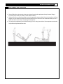
PREASSEMBLY
For future service or related questions:
Please staple your receipt and/or write in the name and phone number of the retail store where you purchased your Smooth
Fitness.
Name: ______________________________ Phone Number: ___________________ Receipt: ______________________
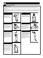
Open the boxes:
You are now ready to open the boxes of your new equipmen
t. Make sure to inventory all of the parts that are included in the boxes.
Check the Parts List for a full count of the number of parts included for this product to be assembled properly. If you are missing
any parts or have any assembly questions call your local dealer or contact us directly at 888-800-1167.
Gather your tools:
Before starting the assembly of your unit, make sure that you have gathered all the necessary tools you may require to assemble
the unit properly. Having all of the necessary equipment at hand will save time and make the assembly quick and hassle-free.
Clear your work area:
Make sure that you have cleared away a large enough space to properly assemble the unit. Make sure the space is free from
anything that may cause injury during assembly. After the unit is fully assembled, make sure there is a comfortable amount of free
area around the unit for unobstructed operation.
Invite a friend:
Some of the assembly steps may require heavy lifting. It is recommended that you obtain the assistance of another person when
assembling this product.
User Weight Limitation:
Please note that there is a weight limitation for this product. If you weigh more than 400lbs. it is not recommended that you use this
product. Serious injury may occur if the user’s weight exceeds the limit shown here. This product is not intended to support users
whose weight exceeds this limit.

www.smoothfitness.com
3
POWER REQUIREMENTS
Power Requirements:
IMPROPER CONNECTION OF THE EQUIPMENT GROUNDING CONNECTOR CAN RESULT IN THE RISK OF AN ELECTRIC
SHOCK. CHECK WITH A QUALIFIED ELECTRICIAN OR SERVICE MAN IF YOU ARE IN DOUBT AS TO WHETHER THE
PRODUCT IS PROPERLY GROUNDED. DO NOT MODIFY THE PLUG PROVIDED WITH THE PRODUCT, IF IT WILL NOT FIT
THE OUTLET; HAVE A PROPER OUTLET INSTALLED BY A QUALIFIED ELECTRICIAN.
This Elliptical can be seriously damaged by sudden voltage changes in your home’s electrical power. Voltage spikes, surges and
noise interference can result from weather conditions or from other appliances being turned on or off. To reduce the possibility of
Elliptical damage, always use a surge protector (not included) with your Elliptical.
Surge protectors can be purchased at most hardware stores. The manufacturer recommends a single outlet surge protector with a
UL 1449 rating as a Transient Voltage Surge Suppressor (TVSS) with a UL suppressed voltage rating of 400V or less and an
electrical rating 120VAC, 15 amps.
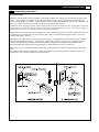
This Elliptical must be grounded to reduce the risk of electrical shock. Grounding provides a path of least resistance for electric
current, should the Elliptical malfunction. This Elliptical is equipped with an electrical cord that has an equipment-grounding
conductor and a grounding plug. Always plug the power cord into a surge protector, and plug the surge protector into an
appropriate outlet that is properly installed and grounded in accordance with all local codes and ordinances.
This product is for use on a nominal 120-volt circuit, and has a grounding plug that looks like the plug illustrated in the drawing
below.
GFCI outlets and GFCI / AFCI Circuit Breakers are NOT recommended for use on this product. GFCI outlets and GFCI / AFCI
Circuit Breakers may cause this equipment to function improperly.

4 SMOOTH CE 9.0 ELLIPTICAL
POWER REQUIREMENTS
Alimentation :
UN MAUVAIS BRANCHEMENT DU CONNECTEUR DE MISE À LA TERRE DE L’ÉQUIPEMENT POURRAIT PROVOQUER UN
CHOC ÉLECTRIQUE. EN CAS DE DOUTE, CONSULTER UN ÉLECTRICIEN OU UN RÉPARATEUR QUALIFIÉ POUR SAVOIR
SI LE PRODUIT EST CORRECTEMENT MIS À LA TERRE. NE PAS MODIFIER LA FICHE FOURNIE AVEC LE PRODUIT. SI
ELLE N’ENTRE PAS DANS LA PRISE, FAIRE INSTALLER UNE PRISE APPROPRIÉE PAR UN ÉLECTRICIEN
PROFESSIONNEL.
Ce elliptique pourrait être gravement endommagé en cas de changement soudain de tension dans votre alimentation électrique.
Les conditions météorologiques ou la mise sous tension ou hors tension d’autres appareils électriques peuvent provoquer des
pointes de tension, des surtensions ou un brouillage. Pour réduire la possibilité que le tapis soit endommagé, toujours utiliser un
limiteur de surtension (non inclus) avec votre elliptique.
Il est possible d’acheter des limiteurs de surtension dans la plupart des quincailleries. Le fabricant recommande un limiteur de
surtension UL 1449 à prise unique comme suppresseur de tension transitoire (TVSS) ayant un taux de suppression de tension de
400 V ou moins et une tension électrique de 110 V C.A., 15 A.
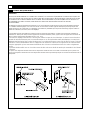
Cet exerciseur elliptique doit être mis à la terre pour réduire le risque de choc électrique. La mise à la terre fournit un
chemin de moindre résistance pour le courant électrique en cas de dysfonctionnement de l'elliptique. Cet exerciseur
elliptique peut être équipé d'un cordon électrique avec un conducteur de terre et une fiche de terre à la terre. Toujours
brancher le cordon d'alimentation dans un suppresseur de surtension et branchez le suppresseur de surtension dans
une prise appropriée qui est correctement installée et mise à la terre conformément à tous les codes et règlements
locaux.
Ce produit doit être utilisé avec un circuit de courant de 110 volts et une feuille de terrain qui ressemble à celui illustré
ci-dessous.
Les prises avec disjoncteur de fuite de terre et les disjoncteurs de fuite de terre ne sont PAS recommandés pour ce produit. Les
prises avec disjoncteur de fuit
e de terre et les disjoncteurs de fuite de terre pourraient provoquer un mauvais fonctionnement de cet
équipement.

www.smoothfitness.com
5
SUPPLIED COMPONENTS
This list identifies the major components you will use to assemble this product.
Main Frame
Upright Tube
Base Frame
Pedal Support Tube (L)
Long Connecting Bars
Console
Pedal L&R
Pedal Support Tube (R)
Rear Stabilizer
Front Stabilizer
Fixed Handlebar
Action Handlebar (R)
Action Handlebar (L)
Second Pedal Support Tube (L)
Second Pedal Support Tube (R)
Tablet Shelf
Upper Upright Post Cover(R)
Power pack
Console Base
Action Arm Cover Front
Lower Upright Post Cover (L&R)
Pedal Support Tube Top Cover (L/R)
Pedal Support Tube Bottom Cover (L/R)
Upper Upright Post Cover (L)

6 SMOOTH CE 9.0 ELLIPTICAL
SUPPLIED COMPONENTS
This list identifies the major components you will use to assemble this product.
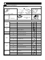
Hardware Pack List By step
Step 1
#19
Screw M8*1.25*72
2
#65
Washer 5/16*16*1.0
2
#20
Nylock nut M8*1.25
2
#21
Plastic cap 5/16
2
Step 2
#19
Screw M8*1.25*72
2
#65
Washer 5/16*16*1.0
2
#20
Nylock nut M8*1.25
2
#21
Plastic cap 5/16
2
Step 3
#18
Allen head bolt M8*1.25*15
8
Step 4
#18
Allen head bolt M8*1.25*15
6
Step 5
#18
Allen head bolt M8*1.25*15
3
#135
Screw M4*16mm
7
#30
Screw M5*0.8*12
4
#6
Screw M8*1.25*15
2
#134
Handlebar cover
1
#136
Screw M3.5*12mm
2
Step 6
#46
Plastic flat round cap
2
#39
Washer 10*22*3T
2
#136
Screw M3.5*12mm
6
#18
Allen head bolt M8*1.25*15
2
#137
Protection cap
2
#138
Large bolt
2
Step 7
#150
Bolt M8*105
4
#20
Nylock nut M8*1.25
4
#30
Screw M5*0.8*12
12
Action Arm Cover Rear
Fan/VST Board
Pedal Tube Cover
Top L/R
Pedal Tube Cover
Bottom L/R
Water Bottle Holder
Console Base Cover
Rear
Hardware box

www.smoothfitness.com
7
SUPPLIED COMPONENTS
This list identifies the major components you will use to assemble this product.
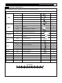
Hardware Pack List By Step cont.
Step 8
#18
Allen head bolt M8*1.25*15
4
#30
Screw M5*0.8*12
2
#17
Washer 10*22*3T
2
#12
Nylock nut M10*1.5
2
#122
Screw 5/32*5/8
12
Step 9
#12
Nylock nut M10*1.5
4
#5
End cap
4
#14
Pedal tube shaft ∮17*97mm
2
#11
Washer 10*32*2T
4
Step 10
#18
Allen head bolt M8*1.25*15
8
Step 11
*
Alignment Bar Preassembled to Rail
4
*
Allen Key
1
Step 12
#135
Screw M4*16mm
7
#30/E
Screw M5*0.8*12
8
Step 13
#18
Allen head bolt M8*1.25*15
4
#65
Washer 5/16*16*1.0
4
#A
Washer M8
4
#122
Screw 5/32*5/8
8
Step 14
#136
Screw M3.5*12mm
2
Step 15
#31
Screw M5*20mm
20
Power Supply
#92
Power ADAPTOR
1
MILLIMETERS

8 SMOOTH CE 9.0 ELLIPTICAL
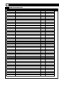
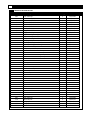
COMPLETE PARTS LIST
Item No.
Description
Qty.
Part No.
1
Handlebar end cap
2
CE90-1
2
Handlebar grip
2
CE90-2
3
T-Bar grip
2
CE90-3
4
Hand pulse grip unit
2
CE90-4
5
Protective cap
4
CE90-5
6
Screw M8*1.25*15
2
CE90-6
7
Locking washer
2
CE90-7
8
Washer
∮
25.4
2
CE90-8
9
Sleeve O.D. 25.4MM
4
CE90-9
10
Sleeve
8
CE90-10
11
Washer 10*32*2T
6
CE90-11
12
NY lock nut M10*1.5
9
CE90-12
13
Pedal tube shaft
∮
17*70mm
2
CE90-13
14
Pedal tube shaft
∮
17*97mm
2
CE90-14
15
Bearing 2203RS
4
CE90-15
16
Retainer R40
4
CE90-16
17
Washer 10*22*3T
2
CE90-17
18
Allen head bolt M8*1.25*15
38
CE90-18
19
Screw M8*1.25*72
4
CE90-19
20
NY lock nut M8*1.25
10
CE90-20
21
Plastic cap 5/16
4
CE90-21
22
Large square plastic cap
2
CE90-22
23
Rear foot cover
2
CE90-23
24
Front foot cover (middle)
2
CE90-24
25
Left roller holder
1
CE90-25
26
Right roller holder
1
CE90-26
27
Wheel
2
CE90-27
28
Screw M8*50
2
CE90-28
29
Screw M4*16mm
6
CE90-29
30
Screw M5*0.8*12
16
CE90-30
31
Screw M5*20
29
CE90-31
32
Screw M4*8
8
CE90-32
33
Bearing 6003
2
CE90-33
34
Bearing
∮
17mm
4
CE90-34
35
Screw M6*15
1
CE90-35
36
Locking screw M8*1.25*30
1
CE90-36
37
Spacer 17*28*1.0
8
CE90-37
38
Screw M8*1.25*65
6
CE90-38
39
Washer 8*25mm
20
CE90-39
40
Screw M8*1.25*30
1
CE90-40
41
Nut M8
3
CE90-41
42
Spring 3.5mm*21mm
1
CE90-42
43
Console
1
CE90-43
44
P.U.Roller
2
CE90-44
45
Screw M5*15
4
CE90-45
46
Plastic flat round cap
2
CE90-46
47
Flywheel 250
1
CE90-47
48
Speed Sensor Cable
1
CE90-48

www.smoothfitness.com
9
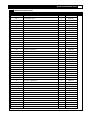
COMPLETE PARTS LIST
Item No.
Description
Qty.
Part No.
49
Belt 550 J6
1
CE90-49
50
Tool storage cover
1
CE90-50
51
Plastic flat round cap
2
CE90-51
52
Pedals
2
CE90-52
53
Pedal bracket
2
CE90-53
54
Adjustable foot
2
CE90-54
55
Small square plastic cap
2
CE90-55
56
End cap (T-Bar)
2
CE90-56
57
Rear cover left
1
CE90-57
58
Rear cover right
1
CE90-58
59
Outer rear cover left
1
CE90-59
60
Outer rear cover right
1
CE90-60
61
Screw M3*10mm
1
CE90-61
62
Motor
1
CE90-62
63
D- Axle
∮
15**182mm
1
CE90-63
64
Magnet
∮
14.8*7L
1
CE90-64
65
Washer 5/16*16*1.0
4
CE90-65
66
Pulley
2
CE90-66
67A
Base frame
1
CE90-67A
67B
Main frame
1
CE90-67B
68
Upright tube
1
CE90-68
69
Swivel tube, LH
1
CE90-69
70
Swivel tube, RH
1
CE90-70
71
Fixed handle bar
1
CE90-71
72
Handle bar, LH
1
CE90-72
73
Handle bar, RH
1
CE90-73
74A
Left pedal arm front
1
CE90-74A
74B
Left pedal arm rear
1
CE90-74B
75A
Right pedal arm front
1
CE90-75A
75B
Right pedal arm rear
1
CE90-75B
76
Front foot ( Stabilizer )
1
CE90-76
77
Rear foot ( Stabilizer )
1
CE90-77
78
Flywheel holder bracket
1
CE90-78
79
Belt tensioner
1
CE90-79
80
Metal cross, LH
1
CE90-80
81
Metal cross, RH
1
CE90-81
82
NY lock nut M12
6
CE90-82
83
Retainer R12
2
CE90-83
84
Metal plate
2
CE90-84
85
Roller axle
∮
12**103mm
2
CE90-85
86
Connecting tube
2
CE90-86
87
Left decorative cover
1
CE90-87
88
Right decorative cover
1
CE90-88
89
Console cable 990MM
1
CE90-89
90A
Cable 1300MM
1
CE90-90A

10 SMOOTH CE 9.0 ELLIPTICAL
COMPLETE PARTS LIST
Item No. Description Qty. Part No.
90B
Main cable top
1
CE90-90B
91
Power wire 750MM
1
CE90-91
92
Power ADAPTOR
1
CE90-92
93
Washer
∮
17*
∮
12*
T
1.0
3
CE90-93
94
Washer
∮
35*
∮
12*
T
2.0
1
CE90-94
95
Washer
∮
35*
∮
6*
T
2.0
1
CE90-95
96
Bearing 6001
6
CE90-96
97A
Toggle switch left
1
CE90-97A
97B
Toggle switch right
1
CE90-97B
98
Square moving arms (L)
1
CE90-98
99
Square moving arms (R)
1
CE90-99
100
Long connecting bar
2
CE90-100
101
Swinging axle plate
2
CE90-101
102
Second pedal support tube left
1
CE90-102
103
Second pedal support tube right
1
CE90-103
104
Step foot cover-Top
2
CE90-104
105
Step foot cover-Bottom
2
CE90-105
106
Decorative front cover for left step tube
1
CE90-106
107
Decorative rear cover for left step tube
1
CE90-107
108
Decorative front dover for right step tube
1
CE90-108
109
Decorative rear cover for right step tube
1
CE90-109
110
Roller cover
2
CE90-110
111
Screw M5*8
3
CE90-111
112
Bearing 6002
4
CE90-112
113
Aluminum rail
2
CE90-113
114
Axle for inner adjustor
1
CE90-114
115
Base for inner adjustor
1
CE90-115
116
Outer adjustor
1
CE90-116
117
Connecting axle for lift motor
1
CE90-117
118
Holder for lift motor
2
CE90-118
119
Adjustor connector
2
CE90-119
120
Hex head screw M10×70mm
1
CE90-120
121
Lift motor
1
CE90-121
122
Screw 5/32*5/8
24
CE90-122
123
Arm cover front
2
CE90-123
124
Arm cover rear
2
CE90-124
125
Base bracket for lift motor
1
CE90-125
126
Hex head screw M10×40mm
1
CE90-126
127
Bottle holder
1
CE90-127
128
Vest control board
1
CE90-128
90B
Main cable top
1
CE90-90B
129
380 Pulley rim
2
CE90-129
130A
Upright post cover
1
CE90-130A
130B
Upright post cover
1
CE90-130B
131
Console base
1
CE90-131

www.smoothfitness.com
11
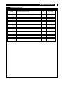
COMPLETE PARTS LIST
Item No. Description Qty. Part No.
132B
Right upper upright post cover
1
CE90-132B
133
Front computer cover
1
CE90-133
134
Front cover
1
CE90-134
135
Screw M4*16mm
11
CE90-135
136
Screw M3.5*12mm
8
CE90-136
137
Adjustor end cap
2
CE90-137
138
Large adjustor screw M10
2
CE90-138
139
Fan network
1
CE90-139
140
FAN
1
CE90-140
141
Cable for Fan
1
CE90-141
142
Fan and vest control board
1
CE90-142
143
Inner small handlebar
2
CE90-143
144A
Handlebar cover front
2
CE90-144A
144B
Handlebar cover rear
2
CE90-144B
145
Rear console base cover
1
CE90-145
146
Adjustor guide cover
2
CE90-146
147
Adjustor fixed cover
2
CE90-147
148
Adjustor rod cover
8
CE90-148
149
Tablet holder
1
CE90-149
150
Screw M8*105
4
CE90-150
#A
Washer M8
4
CE90-#A

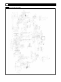
12 SMOOTH CE 9.0 ELLIPTICAL
EXPLODED DIAGRAM

www.smoothfitness.com
13
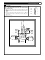
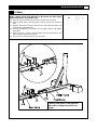
ASSEMBLY
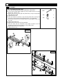
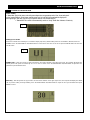
STEP 1: Attach the Front Support (Front Stabilizer)
NOTE: To make attaching the support easier, place a large Styrofoam
block under the machine.
(A) Attach the front support to the base frame with the wheels facing
outward.
(B) Align the 2 bolt holes in the front support with the bolt holes in the main
frame.
(C) Secure the front support to the main frame by using 2 x #19 bolts
inserted through the bottom, 2 x # 65 washers 2 x 20 lock nuts and 2 x
#21 nut covers
(D) Tighten all bolts now.
#19
2
#65
2
#20
2
#21
2

14 SMOOTH CE 9.0 ELLIPTICAL
ASSEMBLY
STEP 2: Attach the Rear Support (Rear Stabilizer)
NOTE: To make attaching the support easier, place a large Styrofoam
block under the machine.
(A) Attach the rear support to the base frame
(B) Align the 2 bolt holes in the rear support with the bolt holes in the main
frame.
(C) Secure the rear support to the main frame by using 2 x #19 bolts inserted
through the bottom, 2 x # 65 washers 2 x 20 lock nuts and 2 x #21 nut
covers
(D) Tighten all bolts now.
#19
2
#65
2
#20
2
#21
2

www.smoothfitness.com
15
ASSEMBLY
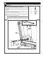
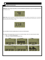
STEP 3: Attach the Base Frame to the Main Frame
NOTE: Caution: Pinch Point Warning Do Not Pinch the Data Cables
Between the Frames. Keep Hands Clear.
(A) Place the base frame flat on the ground in front of the base frame.
(B) Slide the base frame connecting tube inside the main frame connector
tube
(C) Align the main frame bolt holes with the base frame threaded holes and
hand tighten all eight #18 bolts.
(D) Once all eight #18 bolts are inserted, use the Allen wrench to fully tighten
all the bolts.
(E) Now connect the computer cable extending from the main frame to the
cable extending from the base frame.
(F) Insert any extra cable length back in to the frame.
#18
8
Caution: Pinch Point. Do not pinch the
data cables or fingers between the two
frames.

16 SMOOTH CE 9.0 ELLIPTICAL
ASSEMBLY
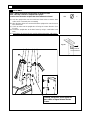
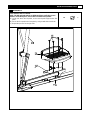
STEP 4: Attach the Upright Tube Assembly to the Base Frame
NOTE: This step is easier to complete with 2 people
! Caution Pinch Point: Do not pinch the wires between the frames!
(A) Hold the upright tube over the round base frame tube so that the data
cable can be connected prior to assembly
(B) After the data cables are connected slide the upright tube onto the round
base frame tube.
(C) Check to make sure the upright tube is facing the correct direction. (See
Fig. 4A)
(D) Secure the upright tube to the base frame by using 6 x #18 Allen head
bolts.
(E) Hand tighten all the bolts first Do not fully tighten these bolts until step 11.
#18
6
Facing towards the
back of the machine
Fig 4A
Caution: Pinch Point. Do not pinch the
data cables or fingers between the two
frames.

www.smoothfitness.com
17
ASSEMBLY
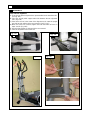
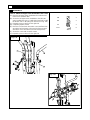
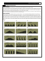
STEP 5:Attach the Console Base, Upright Covers and Handlebars
(A) Place the console base #131 on top of the upright tube #68 and align the
bolt holes (See Fig. 5A)
(B) Secure the console base to the upright tube by using 3 x #18 Allen bolts.
Completely tighten the bolts now
(C) Attach the upper upright covers #132A and 132B around the upright post
and secure the covers together by using 7 x #135 screws and 4 x #30
screws. (See Fig.5B2) Do not completely tighten these screws until step 6
(D) Feed the heart rate wire and toggle switch wires for the hand grips through
the small hole below the handlebar bracket and then up through the top of
the upright tube. Lay the wires over the top of console base covers
(E) Attach and secure the handle bars to the handle bar bracket on the upright
tube by using 2 x #6 Allen head bolts. Completely tighten the bolts (See
Fig 5C) Tighten the handlebar bolts now.
(F) Place the handlebar cover over the handlebar bolts and secure it to the
upper upright post covers by using 2 x #136 screws.
#18
3
#135
7
#30
4
#6
2
#134
1
#136
2
Fig 5A
1
2
3
4
5
6
Fig 5B2
Control board
Fig 5C
Fig 5B1

18 SMOOTH CE 9.0 ELLIPTICAL
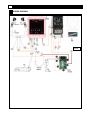
WIRING DIAGRAM
Fig. 6B

www.smoothfitness.com
19
ASSEMBLY
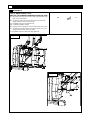
STEP 6: Attach the Fan and Handlebar Covers
(A) Place the fan cover #133 in-between the #132A and #132B covers (See
Fig.6A).
(B) Take the fan wire and route it with the other wires from the handrail
assembly
(C) Secure the fan cover #133 by using 4 x #136 screws.
(D) Attach the Handlebar cover #134 and secure it using 2 x #136 screws.
(E) Fully tighten all screws for covers #133, #134, #132A and 132B (See
Fig.6B)
(F) Place the two long connecting bars on to the swinging axel plate #101
and the opposite end on the stride adjuster. Be certain that the Long
connection bar is facing the correct direction (See Fig. 6C)
(G) Secure both long connecting bars to the swinging axel plates #101 by
using 2x #18 Allen head bolts, 2x #39 M8 Washer.
(H) Completely tighten the #18 bolts and insert the plastic cap
(I) Secure the long connecting bars to the stride adjuster by using 2 x #138
large bolts. (See Fig. 6D)
(J) Completely tighten the large bolts then cover with 2 x #137 protective cap
#136
6
#18
2
#39
2
#46
2
#137
2
#138
2
Fig. 5D
Fig.6A
Fig.6B
Fig.6C

20 SMOOTH CE 9.0 ELLIPTICAL
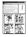
ASSEMBLY
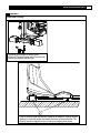
STEP 7: Assembling the Pedal Tubes
(A) Place both the left pedal tubes #74A and #74B on a flat surface.
(B) Secure the two pedal tubes together by using 2x #150 bolts and 2 x #20
Nylock nuts. (See Fig. 7A)
(C) Repeat the process for the right side pedal tube by using the right pedal
tubes #175A and 175B
(D) Tighten all bolts now.
(E) Place the aluminum rail #133 on top of the left pedal tubes and align the
bolt holes on the aluminum rail with the bolt holes on the pedal tube.
(F) Secure the aluminum rail to the pedal tubes by using 4x#30 screws. See
(Fig. 7B)
(G) Tighten all the bolts now.
(H) Repeat the process for the left side pedal tube
(I) Place the front and rear decorative covers #106 and
#107 over the
aluminum rail bolts and secure them by using 2x#30 screws
(J) Repeat this process for the right side.
(K) Tighten all bolts now
#150
4
#20
4
#30
12
Fig. 7B
Fig. 7A
Page is loading ...
Page is loading ...
Page is loading ...
Page is loading ...
Page is loading ...
Page is loading ...
Page is loading ...
Page is loading ...
Page is loading ...
Page is loading ...
Page is loading ...
Page is loading ...
Page is loading ...
Page is loading ...
Page is loading ...
Page is loading ...
Page is loading ...
Page is loading ...
Page is loading ...
Page is loading ...
Page is loading ...
Page is loading ...
Page is loading ...
Page is loading ...
Page is loading ...
Page is loading ...
Page is loading ...
-
 1
1
-
 2
2
-
 3
3
-
 4
4
-
 5
5
-
 6
6
-
 7
7
-
 8
8
-
 9
9
-
 10
10
-
 11
11
-
 12
12
-
 13
13
-
 14
14
-
 15
15
-
 16
16
-
 17
17
-
 18
18
-
 19
19
-
 20
20
-
 21
21
-
 22
22
-
 23
23
-
 24
24
-
 25
25
-
 26
26
-
 27
27
-
 28
28
-
 29
29
-
 30
30
-
 31
31
-
 32
32
-
 33
33
-
 34
34
-
 35
35
-
 36
36
-
 37
37
-
 38
38
-
 39
39
-
 40
40
-
 41
41
-
 42
42
-
 43
43
-
 44
44
-
 45
45
-
 46
46
-
 47
47


Smooth Fitness SMOOTH CE-9.0 ELLIPTICAL User manual
- Type
- User manual
- This manual is also suitable for
Ask a question and I''ll find the answer in the document
Finding information in a document is now easier with AI
in other languages
Related papers
-
 Smooth Fitness CE-8.0LC Owner's manual
-
 Smooth Fitness CE-8.0LC User manual
-
 Smooth Fitness REV 400 User manual
-
 Smooth Fitness EVO REV 300 User manual
-
 Smooth Fitness CE-5.5 Elliptical User manual
-
 Smooth Fitness CE-3.0 XT User manual
-
 Smooth Fitness CE-2.5 Elliptical User manual
-
 Smooth Fitness SMOOTH CE3.7 User manual
-
 Smooth Fitness CE-3.0 User manual
-
 Smooth Fitness CE 7.4 User manual


Other documents
-
SportsArt 803 Owner's manual
-
 Furniture of America IDF-AC533-3 Installation guide
-
 mater Canopy Terho Pendant Light User manual
-
Fitness Quest Edge 1400 Owner's manual
-
Imperial 500C Operating instructions
-
Black Widow TB-SEAT User manual
-
 LifeCore Fitness 985VGs User manual
-
 AceProAV AcePro-CE90-1 Quick start guide
-
Life Fitness X7 User manual
-
Keys Fitness CardioMax 700e User manual


