Page is loading ...

USER’S MANUAL
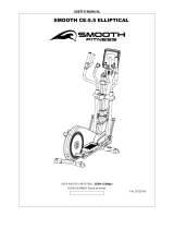
SMOOTH CE-2.5 ELLIPTICAL
USER WEIGHT LIMITATION: 300lbs(136kgs).
SERIAL NUMBER (found on frame):
Ver. 20121016

2
SMOOTH CE 2.5 ELLIPTICAL
PREASSEMBLY
For future service or related questions:
Please staple your receipt and/or write in the name and phone number of the retail store where you purchased your Smooth
Fitness.
Name: ______________________________ Phone Number: ___________________ Receipt: ______________________
Open the boxes:
You are now ready to open the boxes of your new equipment. Make sure to inventory all of the parts that are included in the boxes.
Check the Parts List for a full count of the number of parts included for this product to be assembled properly. If you are missing
any parts or have any assembly questions call your local dealer or contact us directly at 888-800-1167.
Gather your tools:
Before starting the assembly of your unit, make sure that you have gathered all the necessary tools you may require to assemble
the unit properly. Having all of the necessary equipment at hand will save time and make the assembly quick and hassle-free.
Clear your work area:
Make sure that you have cleared away a large enough space to properly assemble the unit. Make sure the space is free from
anything that may cause injury during assembly. After the unit is fully assembled, make sure there is a comfortable amount of free
area around the unit for unobstructed operation.
Invite a friend:
Some of the assembly steps may require heavy lifting. It is recommended that you obtain the assistance of another person when
assembling this product.
User Weight Limitation:
Please note that there is a weight limitation for this product. If you weigh more than 250lbs. it is not recommended that you use this
product. Serious injury may occur if the user’s weight exceeds the limit shown here. This product is not intended to support users
whose weight exceeds this limit.

www.smoothfitness.com
3
SUPPLIED COMPONENTS
This list identifies the major components you will use to assemble this product.

4
SMOOTH CE 2.5 ELLIPTICAL
SUPPLIED HARDWARE
Base Frame
Upright Tube
Console
Pedal Support Tube (L)
Pedal (R/L)
Pedal Support Tube (R)
Rear Stabilizer
Front Stabilizer
Fixed Handlebar
Swing Arm Handlebar (R)
Swing Arm Handlebar (L)
Upright Tube Front Cover
Upright Tube Rear Cover
Power pack
Console Base
Swing Arm Cover Front
Console Base Cover (L)
Front Pedal Tube Cover Top (L/R)
Rear Pedal Tube Cover Bottom (L/R)
Front Pedal Tube Cover Bottom (L/R)
Rear Pedal Tube Cover Bottom (L/R)
Bottle Holder
Rear Console
Base Cover
CE-2.5
Hardware

www.smoothfitness.com
5
Hardware Pack List By step
Step 1
#19
Screw M8*1.25*72
2
#65
Washer 5/16*16*1.0
2
#20
Nylock nut M8*1.25
2
#21
Plastic cap 5/16
2
Step 2
#19
Screw M8*1.25*72
2
#65
Washer 5/16*16*1.0
2
#20
Nylock nut M8*1.25
2
#21
Plastic cap 5/16
2
Step 3
#18
Allen head bolt M8*1.25*15
6
#115
Screw M4*16mm
4
Step 4
#29
Screw 3.5*12mm
8
#30
Screw M5*0.8*12
2
#12
Nylock nut M10*1.5
2
#17
Washer 10*22*3T
2
#44
Knob 2
2
Step 5
#18
Allen head bolt M8*1.25*15
3
#29
Screw M3.5*12
4
#30
Screw M5*0.8*12
2
#6
Screw M8*1.25*15
2
Step 6
#116
Screw M3.5*12mm
6
#88
Front cover
1
MILLIMETERS
SUPPLIED HARDWARE
Action Arm Cover Rear
Console Base Cover (R)
Upright Post Cover (L)
Upright Post Cover (R)

6
SMOOTH CE 2.5 ELLIPTICAL
Step 7
E
4
#30
Screw M5*0.8*12
2
Step 8
#18
Allen head bolt M8*1.25*15
4
#65
Washer 5/16*16*1.0
4
#A
Washer M8
4
#29
Screw M3.5*12
8
Step 9
#29
Screw M3.5*12
4
#104
Screw M4*12
4
#18
Allen head bolt M8*1.25*15
8
Step10
#106
power adapter
1

www.smoothfitness.com
7
COMPLETE PARTS LIST
c
Description
Qty.
Part No.
1
Handlebar end cap
2
CE25-1
2
Handlebar grip
2
CE25-2
3
T-Bar grip
2
CE25-3
4
Hand pulse grip unit
2
CE25-4
5
Fan network
1
CE25-5
6
Screw M8*1.25*15
2
CE25-6
7
Locking washer
2
CE25-7
8
Washer ∮25.4
4
CE25-8
9
Sleeve ∮25.4
4
CE25-9
10
Sleeve
4
CE25-10
11
Washer 10*32*2T
2
CE25-11
12
Nylock nut M10*1.5
4
CE25-12
13
Pedal tube shaft
2
CE25-13
14
Washer 19*38*1.6
4
CE25-14
15
Bearing 22032RS
2
CE25-15
16
Retainer R40
2
CE25-16
17
Washer 10*22*3T
2
CE25-17
18
Allen head bolt M8*1.25*15
14
CE25-18
19
Screw M8*1.25*75
6
CE25-19
20
Nylock nut M8*1.25
12
CE25-20
21
Plastic cap 5/16
4
CE25-21
22
Allen head bolt M8*50
2
CE25-22
23
Rear square foot cap
2
CE25-23
24
Front square foot cap
2
CE25-24
25
Left roller holder
1
CE25-25
26
Right roller holder
1
CE25-26
27
Wheel
2
CE25-27
28
Plastic Ring
2
CE25-28
29
Screw M3.5*12
28
CE25-29
30
Screw M5*0.8*12
17
CE25-30
31
Screw M5*20
15
CE25-31
32
Screw M4*8
24
CE25-32
33
Bearing 6003
2
CE25-33
34
Metal Spring plate
2
CE25-34
35
Screw
1
CE25-35
36
Locking screw M8*1.25*30
1
CE25-36
37
Spacer 17*28*1.0
4
CE25-37
38
Screw M8*1.25*65
6
CE25-38
39
Washer 8mm*25mm
13
CE25-39
40
Screw M8*1.25*30
1
CE25-40
41
Nut
3
CE25-41
42
Spring 3.5mm*21mm
1
CE25-42
43
Meter
1
CE25-43
44
Knob2
2
CE25-44
45
Screw M5*15
4
CE25-45
46
Nut M10
1
CE25-46
47
Flywheel
1
CE25-47
48
Speed Sensor Cable 650MM
1
CE25-48

8
SMOOTH CE 2.5 ELLIPTICAL
COMPLETE PARTS LIST
Item No.
Description
Qty.
Part No.
49
Belt 650J
1
CE25-49
50
End cap
2
CE25-50
51
Drive pulley 6001
2
CE25-51
52
Pedal, LH
1
CE25-52
53
Pedal, RH
1
CE25-53
54
Adjustable foot
2
CE25-54
55
2
CE25-55
56
End cap (T-Bar)
2
CE25-56
57
Middle cover, LH
1
CE25-57
58
Middle cover, RH
1
CE25-58
59
Side cover, LH
1
CE25-59
60
Side cover, RH
1
CE25-60
61
FAN
1
CE25-61
62
motor
1
CE25-62
63
Screw M5*20
16
CE25-63
64
Magnet ∮14.5*7L
1
CE25-64
65
Washer 5/16*16*1.0
10
CE25-65
66
Pulley
2
CE25-66
67
Base frame
1
CE25-67
68
Upright tube
1
CE25-68
69
Swivel tube, LH
1
CE25-69
70
Swivel tube, RH
1
CE25-70
71
Fix handle bar
1
CE25-71
72
Handle bar, LH
1
CE25-72
73
Handle bar, RH
1
CE25-73
74
Pedal tube, left
1
CE25-74
75
Pedal tube, right
1
CE25-75
76
Front foot
1
CE25-76
77
Rear foot
1
CE25-77
78
Flywheel holder bracket
1
CE25-78
79
Belt ightener
1
CE25-79
80
Metal cross, LH
1
CE25-80
81
Metal cross, RH
1
CE25-81
82
Cable for Fan
1
CE25-82
83
Fan control board
1
CE25-83
84
Metal plate
2
CE25-84
85
Connecting tube Left
1
CE25-85
86
Connecting tube Right
1
CE25-86
87(A)
Front cover, LH
1
CE25-87(A)
87(B)
Front cover, RH
1
CE25-87(B)
88
Front cover
1
CE25-88

www.smoothfitness.com
9
COMPLETE PARTS LIST
Item No.
Description
Qty.
Part No.
89
Console cable 900MM
1
CE25-89
90
Washer ∮17
2
CE25-90
91
Cable 950mm
1
CE25-91
92
power wire 850mm
1
CE25-92
93
Front cover for upright tube
1
CE25-93
94
Rear cover for upright tube
1
CE25-94
95
Rear cover for swivel tube
2
CE25-95
96
Front cover for swivel tube
2
CE25-96
97
Top step foot cover
2
CE25-97
98
Bottom step foot cover
2
CE25-98
99
Pedal tube cover top L
1
CE25-99
100
Pedal tube cover bottom L
1
CE25-100
101
Pedal tube cover top R
1
CE25-101
102
Pedal tube cover bottom R
1
CE25-102
103
disc rim
2
CE25-103
104
Screw M4*12
4
CE25-104
105
bottle holder
1
CE25-105
106
power adapter
1
CE25-106
107
Screw M4*25
2
CE25-107
108
Cable 420MM
1
CE25-108
109
Washer ∮35*∮6*T2.0
1
CE25-109
110
Washer ∮17*∮12*T1.0
3
CE25-110
111
Washer ∮35*∮12*T2.0
1
CE25-111
112
Console bare
1
CE25-112
113A
Left meter bare cover
1
CE25-113A
113B
Right meter bare cover
1
CE25-113B
114
Front meter bare cover
1
CE25-114
115
Screw M4*16
4
CE25-115
116
Screw M3.5*12
6
CE25-116
117
Rear console bare cover
1
CE25-117
118A
Left upright post cover
1
CE25-118A
118B
Right upright post cover
1
CE25-118B
#A
Washer M8
4
CE25-#A

10
SMOOTH CE 2.5 ELLIPTICAL
ASSEMBLY
STEP 1: Attach the Front Support (Front Stabilizer)
NOTE: To make attaching the support easier place a large Styrofoam
block under the machine.
(A) Attach the front support to the base frame with the wheels facing
outward.
(B) Align the 2 bolt holes in the front support with the bolt holes in the
main frame.
(C) Secure the front support to the main frame by using 2 x #19 bolts
inserted through the bottom, 2 x # 65 washers 2 x 20 lock nuts and 2
x #21 nut covers
(D) Tighten all bolts now.
#19
2
#65
2
#20
2
#21
2

www.smoothfitness.com
11
ASSEMBLY
STEP 2: Attach the Rear Support (Rear Stabilizer)
NOTE: To make attaching the support easier place a large Styrofoam
block under the machine.
(A) Attach the rear support to the base frame
(B) Align the 2 bolt holes in the rear support with the bolt holes in the main
frame.
(C) Secure the rear support to the main frame by using 2 x #19 bolts
inserted through the bottom, 2 x # 65 washers 2 x 20 lock nuts and 2 x
#21 nut covers
(D) Tighten all bolts now.
#19
2
#65
2
#20
2
#21
2

12
SMOOTH CE 2.5 ELLIPTICAL
ASSEMBLY
STEP 3: Attach the Upright Tube Assembly to the Base Frame
NOTE: This step is easier to complete with 2 people
!Caution Pinch Point: Do not pinch the wires between the frame!
(A) Hold the upright tube over the round base fram tube so that the data
cable can be connected prior to assembly
(B) After the data cable is connected slide the upright tube onto the round
base frame tube.
(C) Check to make sure the upright tube is facing the correct direction.
(See Fig.3 A)
(D) Secure the upright tube to the base frame by using 6 x #18 Allen head
bolts.
(E) Hand tighten all the bolts first, then completely tighten the bolts near
the label marked 1 with the Allen wrench. (See Fig. 3B)
(F) Now completely tighten all bolts with the Allen wrench.
(G) Place the left and right upright tube covers #118A/118B around the
upright tube and secure them by using 4 x #115 screws(See Fig. 3C)
#18
6
#115
4
Facing towards the
back of the machine
Fig 3A
Fig 3B
Fig 3C

www.smoothfitness.com
13
ASSEMBLY
STEP 4: Attach the Pedal Tube Assembly
(A) Locate the left and right pedal tube assemblies (#74 and #75)
(B) Attach the front pedal covers top and bottom #97/#98 to the left pedal
by using 2x #29 screws and 1 x #30 screw. (See Fig. B)
(C) Repeat the process for the right side pedal tube
(D) Attach the left pedal tube to the base frame crank arm (See Fig. C)
(E) Secure the pedal tube to the base frame crank arm by using 1 x #17
washer and 1 x #12 M10 lock nut. Completely tighten with a wrench
(F) Attach and secure the Rear pedal tube covers #101 and #102 to the
left pedal tube by using 4 x #29 screws.
(G) Repeat theis process for the right side.
(H) Insert the front left of the pedal tube #85 on to Action handle bar tube
#69 and secure them together by using the adjuster knob # 44 (See
Fig. D)
(I) Repeat the process for the right side.
Note: Tighten all fasteners!
#29
4
#30
2
#12
2
#17
2
#29
8
#44
2
Fig. C
Fig. D
Fig. E

14
SMOOTH CE 2.5 ELLIPTICAL
ASSEMBLY
STEP 5:Attach the Console Base and Handlebars
(A) Place the console base on top of the upright tube and align the bolt
holes (See Fig. 5A)
(B) Secure the console base to the upright tube by using 3 x #18 Allen
bolts. Completely tighten the bolts now
(C) Attach the console base covers #113A and 113B around the console
base and secure the covers together by using 4 x #29 screws and 4
x #30 screws. (See Fig.5B) Do not completely tighten these screws
until step 6
(D) Feed the Heart rate wire of the hand grips through the small hole
below the handlebar bracket then up through the top of the upright
tube. Lay the wires over the top of console base covers
(E) Attach and secure the handle bars to the handle bar bracket on the
upright tube by using 2 x #6 Allen head bolts. Completely tighten the
bolts (See Fig 5C)
#18
3
#29
4
#30
2
#6
2
Fig. 5A
Fig. 5B
Fig. 5 C

www.smoothfitness.com
15
ASSEMBLY
STEP 6: Attach the Fan Cover and Handlebar Cover
(A) Place the fan cover #114 in-between the #113A and #113B covers (See
Fig.6A).
(B) Take the fan wire and route it with the other wires from the handrail
assembly
(C) Secure the fan cover #114 by using 4 x #116 screws.
(D) Attach the Handlebar cover #88 and secure by using 2 x #116 screws.
Fully tighten all screws for covers #88, #114, #113A and 113B (See Fig.6B)
#116
6
Fig. 6A
Fig. 6B

16
SMOOTH CE 2.5 ELLIPTICAL
ASSEMBLY
STEP 7: Attach the Computer and Console Base Rear Cover
(A) Connect the 4 wires from the computer #112 to the 4 wires that were
placed over the Console base covers. (these are the wires that ran up
through the upright tube and the handle bar contact heart rate)
(B) Place the computer # 43 on to the console base #112 (See Fig. 7A)
(C) Put the excess wires in to the back of the computer and in to the console
base covers. Be sure not to punch the wires between the computer and
the frame.
(D) Secure the computer to the console base using 4 x E screws and tighten
completely.
(E) Place the console base rear cover on the other console base and secure
it by using 2 x #30 screws
(F) Tighten all screws now.
E
4
#30
2
Fig. 7A
Fig. 7B

www.smoothfitness.com
17
ASSEMBLY
STEP 8: Attach the Upper Swing Arm Assembly and Covers
(A) Place the upper swing arms left and right #72/#73 in to the lower swing
arms #69/#70
(B) Secure the upper and lower swing arms together by using 4 x #18
Allen bolts, 4 x #A spring washer and 4 x #65 washers.
(C) Tighten all bolts now
(D) Place the Place the front and rear swing arm covers #96/#95 around
the swing arms.
(E) Secure the covers together by using 8 x #29 screws.
(F) Tighten all screws now
#18
4
#65
4
#A
4
#29
8
Fig. 8A
Fig. 8B

18
SMOOTH CE3.6 ELLIPTICAL
ASSEMBLY
STEP 9: Attach the Bottle Holder and Pedals
(A) Attach the rear cover #94 to the bottle holder #105and secure by using 4 x
#104 screws.
(B) Place the front cover and the rear cover with the bottle holder attached
around the upright tube and secure by using 4 x #29 screws (See Fig. 9A)
(C) Locate the left and right pedals. Place them on the pedal tubes with the side
opening facing outward away from the machine (see Fig. 9B)
(D) Secure the pedals to the pedal tube by using 4 x #18 screws.
(E) Tighten all bolts and screws now.
#29
4
#104
4
18
8
Fig. 9A
Fig. 9B

www.smoothfitness.com
19
ASSEMBLY
STEP 10: Attach the Power Supply
(A) Before plugging in the power supply verify the voltage specifications on
the lable.
(B) Plug the adaptor jack in to the inlet on the bottom rear of the elliptical.
(C) Plug the power supply in to the wall outlet.
#106
1

20
SMOOTH CE3.6 ELLIPTICAL
Mp3, Fan and Procedure to Move the Equipment
Mp3 and iPod Usage
To play music or audio books through the console sound system while you exercise, plug the included audio
cable into the jack on the back of the console and into a jack on your MP3 or iPod; make sure that the audio
cable is fully plugged in. Next, press the play button on your MP3 player or IPOD. Adjust the volume level using
the volume control on your MP3 or IPOD.
Smooth Breeze Fan
Cooling Fan is included with the unit to increase the Air Circulation during your exercise. To operate press the
“Fan” key to turn on. To turn the fan off, press the “Fan” key again to stop the fan.
Transporting the Elliptical
Please follow these instructions when carrying and moving the equipment. Lifting it incorrectly may strain
your back or cause injury
The device is easy to move by pushing along on the integrated transport wheels. Tilt the unit from the front
and pull it along the floor on the wheels.
To prevent the equipment malfunctioning, store in a dry place with as little temperature variation as possible
and protected from dust.
/


