Page is loading ...

Piper Cub - 1
INSTRUCTION MANUEL
GEBRUIKSAANWIJZING
PLAN DE MONTAGE
ANLEITUNG
T0345
WARNING ! This R/C kit and
the model you will build is not
a toy.
LET OP ! Deze bouwdoos van
een radiobestuurd vliegtuig is
geen speelgoed.
ATTENTION ! Ce kit d’avion R/C
n’est pas un jouet.
ACHTUNG ! Dieser Bausatz
von ferngesteurte Model
ist kein Spielzeug.
version: 20/02/2002 • T0345

2 - Piper Cub
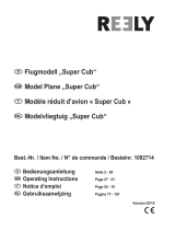
Specifications / Specificaties /
Technische daten / Spécifications
1. Fuselage
2. Vacuum formed motor
cowling
3. Horizontal stabilizer
4. Vertical fin
5. Accessories
6. Wing posts
7. Wheels
8. Landing gear
9. Wing
1. Romp
2. Vacuum gevormde
motorkap
3. Stabilisator
4. Richtingsroer
5. Benodigdheden
6. Vleugelsteunen
7. Wielen
8. Landingsgestel
9. Vleugel
1. Rümpf
2. Motorhaube
3. Höhenruder
4. Seitenruder
5. Stosselstange
6. Flügelstutze
7. Räder
8. Landungsfahrwerk
9. Flügel
1. Fuselage
2. Capotage
3. Stabilisateur horizontal
4. Dérive vertical
5. Tiges pousseur
6. Mâts de haubans
7. Roues
8. Train d’atterrissage
principal
9. Aile
1
2
5
6
7
8
3
4
9
Kit content / Inhoud van de bouwdoos /
Bausatzinhalt / Contenu de la boîte
Length: 670 mm
Wing span: 1080 mm
Wing area: 15,7 dm
2
Wing loading: 38,2 g/dm
2
Power gear: type 400
geared
1:1,85
Propeller: 8 x 4 slim
Flight time: 7 - 10 min
Flying weight: 600 g
Radio required: 4 ch radio with
4 x B112 micro
servos
Batterypack: 8,4V - 600 mAh
Lengte: 670 mm
Spanwijdte: 1080 mm
Vleugelopp.: 15,7 dm
2
Vleugelbel.: 38,2 g/dm
2
Aandrijving: type 400
aandrijving
1:1,85
Propeller: 8 x 4 slim
Vlieg tijd: 7 - 10 min
Vlieg gewicht: 600 g
Radio besturing:4 kanaals radio
met 4 x B112
micro servo’s
Batterijen: 8,4V - 600 mAh
Länge: 670 mm
Spannweite: 1080 mm
Tragflügelinhalt: 15,7 dm
2
Gesamtflachen-
belastung: 38,2 g/dm
2
Antriebsset: type 400
Verkleinung
1:1,85
Luftschraube: 8 x 4 slim
Flugzeit: 7 - 10 min
Fluggewicht: 600 g
Funkfernsteuerung:
4 Kanal
Steuerung mit
4 x B112 micro
servo
Batterie benötigt
:8,4V - 600 mAh
Longueur: 670 mm
Envergure: 1080 mm
Surface de l’aile:15,7 dm
2
Portance de l’aile
: 38,2 g/dm
2
Réducteur: type 400
rapport de
réduction
1:1,85
Hélice: 8 x 4 slim
Temps de vol: 7 - 10 min
Poids en vol: 600 g
Radio requise: 4 cannaux avec
4 x B112 micro
servos
Batterie requise:8,4V - 600 mAh

Piper Cub - 3
Important Safety Notes.
Be sure to read right through the instructions covering assembly and operation of your model before you attempt to operate it for the first time. You alone are
responsible for the safe operation of your radio-controlled model. Young people should only be permitted to build and fly these models under the instruction and
supervision of an adult who is aware of the hazards involved in this activity.
Use only matching polarised connectors. All cables, connectors and the battery if home-assembled must be insulated to prevent short circuits. Never attempt to
combine different types of plug and socket - e.g. tin-plated and gold-plated types - as such combinations are bound to be unreliable.
NC batteries are capable of holding and releasing enormous amounts of energy, and as such represent a constant hazard of explosion and fire.
We have no control over the way you build and operate your RC model aircraft, and for this reason we are obliged to deny all liability for accidents. All we can do is
point out the hazards and make sure you are aware of them.
If you need help, please enlist the aid of an experienced modeller, a model club or enrol at a model flying training school, Model shops and the specialist model
press are also good sources of information. The best course is always to join a club and fly at the approved model flying site.
Rubber bands deteriorate with age and become brittle. Replace them from time to time to maintain the safety and reliability of your model. Stretch all rubber bands
before use to check that they are still strong enough for their purpose.
Motors should only be run in the open air! The powerful suction of the propeller and the volume of air which it accelerates can easily lead to accidents in enclosed
spaces (e.g. pictures falling down, curtains sucked into the propeller). The model must be held securely by an assistant at all times.
Keep well clear of the rotational plane of propellers - don't stand in line with it or in front of it. You never know when some part may come loose and fly off at high
speed, hitting you or anybody else in the vicinity. Never touch the revolving propeller with any object.
There must be no chance of any object getting in the way of the propeller and preventing it rotating.
Take care with loose clothing such as scarves, loose shirts etc. Flapping cloth can easily be sucked into the area of the propeller and then get tangled in it.
If you start your motor when the model is standing on loose or sandy ground, the propeller will suck up sand and dust and hurl it around. and it could easily get in
your eyes. Wear protective goggles at such times.
Every time you intend to operate your model check carefully that it and everything attached to it (e.g. propeller, gearbox,RC components etc.) are in good condition
and undamaged. If you find a fault do not fly the model until you have corrected it.
Satisfy yourself that your frequency is vacant before you switch on. Radio interference caused by unknown sources can occur at any time without warning. If this
should happen, your model will be uncontrollable and completely unpredictable. Never leave your radio control system unguarded, as other people might pick it up
and try to use it.
Check that nothing is in the way of the propeller before you switch on the electric motor. Never attempt to stop the spinning propeller.Electric motors with a propeller
attached should only be run when installed securely.
lf you are to fly your model safely and avoid problems it is essential that you are aware of its position and attitude throughout each flight - so don't let it fly too far
away! lf you detect a control problem or interference during a flight,immediately land the model to prevent a potential accident Note that the transmitter throttle stick
must be set to the OFF (motor stopped) position before you switch on the power system. To avoid the electric motor starting unexpectedly, switch on the transmitter
first. then the receiving system. Use the reverse sequence when switching off: receiver first, then the transmitter. Check that the control surfaces move in the correct
"sense" when you operate the sticks.
Please don't misunderstand the purpose of these notes. We only want to make you aware of the many dangers and hazards which can arise if you lack knowledge
and experience, or work carelessly or irresponsibly. If you take reasonable care model flying is a highly creative, instructive, enjoyable and relaxing pastime.
Belangrijke Veiligheidsinstructies
Lees de instructies betreffende montage en werking van je model vooraleer u het de eerste maal in gebruik neemt. U alleen bent verantwoordelijk voor de veilige
werking van uw radiobestuurd model. Kinderen zijn enkel toegestaan om deze modellen te bouwen en te vliegen onder het toeziend oog van een volwassene, die
zich bewust is van de gevaren die dit met zich meebrengt.
Gebruik enkel passende gepolariseerde verbindingsstukken. Alle kabels, verbindingsstukken en de batterij, indien deze zelf samengesteld is, moeten geïsoleerd
worden om kortsluiting te voorkomen. Poog nooit verschillende types van pluggen en contacten te kombineren (vb.tin-en goudcontacten), daar zulke combinaties
onbetrouwbaar zijn.
NC-batterijen zijn geschikt om enorme hoeveelheden energie vast te houden en vrij te geven. Zodoende vertegenwoordigt een batterij een constant risico op
explosie en brandgevaar.
Wij hebben geen controle over de manier waarop u het RC-vliegtuig bouwt en gebruikt. Daarom zijn wij verplicht om alle aansprakelijkheid voor ongevallen van de
hand te wijzen. Het enige dat in onze mogelijkheden ligt is u te waarschuwen voor de risico’s.
Als u hulp nodig heeft, roep dan de bijstand van een ervaren modelbouwer of een modelbouwclub in, of schrijf u in bij een modelvliegclub. Modelshops en de
gespecialiseerde pers zijn eveneens een geschikte bron van informatie. De beste les is echter zich aan te sluiten bij een club en te vliegen op de goedgekeurde
vliegplaatsen.
Rubber elastieken verslijten met het gebruiken en worden broos. Vervang ze tijdig, zodoende stelt u de veiligheid en de betrouwbaarheid van uw model veilig. Span
alle rubber elastieken op vooraleer u ze gebruikt om te controleren of ze nog sterk genoeg zijn.
Motoren mogen enkel buiten in openlucht lopen! De sterke zuigkracht van de propeller en de luchtverplaatsing die deze veroorzaakt, kan in kleine ruimten makkelijk
een ongeval tot gevolg hebben (vb. schilderijen die naar beneden vallen, een gordijn dat in de propeller gezogen wordt). Het model moet steeds stevig worden
vastgehouden door een helper.
Houdt de rotatiebaan van een propeller vrij, sta er nooit voor of in de lijn van de propeller. Er kan steeds een deel loskomen en met hoge snelheid wegvliegen, zodat
het uzelf of iemand anders in de omgeving kan verwonden. Raak de ronddraaiende propeller nooit met enig voorwerp aan. Vermijdt steeds dat welk voorwerp ook
het draaien van de propeller verhindert.
Pas op met losse kleding zoals sjaals, losse shirts, … Losse kleding kan makkelijk in de propeller gezogen worden.
Als u de motor start terwijl deze op losse of zanderige grond staat, zal de propeller het zand opzuigen en rondslingeren zodat het in je ogen kan komen. Draag dus
steeds een veiligheidsbril op zo’n momenten.
Controleer, elke keer als u een model wil gebruiken, zorgvuldig of het model en alles wat erbij hoort (vb. propeller, aandrijving, RC-onderdelen, …) in goede staat en
onbeschadigd is. Als u een fout bemerkt, vlieg dan niet met het model tot u de fout hebt opgelost.
Verzeker uzelf ervan dat de frequentie vrij is vooraleer u de zender aanzet. Radiostoringen veroorzaakt door vreemde bronnen kunnen op elk moment en zonder
waarschuwing voorkomen. Als dit gebeurt is je model oncontroleerbaar en volledig onvoorspelbaar. Laat uw radiobesturing nooit onbewaakt achter, andere mensen
zouden kunnen proberen het te gebruiken.
Controleer of er niets in de baan van de propeller is vooraleer u de electromotor aanzet. Probeer nooit de draaiende propeller te stoppen. Electromotoren verbonden
met een propeller mogen enkel lopen als deze veilig geïnstalleerd is.
Als u uw model veilig wil vliegen en u wil problemen vermijden, dan is het essentieel dat u zich bewust bent van zijn positite en hoogte tijdens iedere vlucht. Laat het
dus niet te ver weg vliegen ! Als u een controleprobleem of storingen ontdekt gedurende een vlucht, landt dan onmiddellijk om een mogelijk ongeval te voorkomen.
Bemerk dat de zenderstick voor de motorfunctie in de off-stand moet staan vooraleer u het systeem aanzet. Om te voorkomen dat de electromotor onverwacht start,
zet eerst de zender aan, later pas de ontvanger. Gebruik de omgekeerde volgorde bij het afzetten : eerst de ontvanger, dan de zender. Controleer of de roeren in de
juiste richting bewegen als u de sticks gebruikt.
Heb begrip voor het doel van deze opmerkingen. Wij willen u enkel opmerkzaam maken voor de vele gevaren en risico’s die zich kunnen voordoen als u kennis en
ervaring mist, nonchalant of onverantwoordelijk te werk gaat.
Als u redelijk zorg draagt, is modelvliegen een zeer creatieve, leerrijke, plezierige en ontspannende vrijetijdsbesteding.

Piper Cub - 5
To assamble this airplane some tools are needed.
Voor het samenstellen van het vliegtuig zijn er enkele gereedschappen nodig.
Zum bauen dieses Flugzeug werden einige Werkzeuge gebraucht .
Certain outils sont requis pour assembler cet avion.
Tools & items / Gereedschap & benodigdheden /
Werkzeuge und erforderliches / Outils et équipements
Sharp hobby knife / Scherp hobby mes /
Couteau de modeliste / Hobby messer
Needle nose pliers / Bek tang /
Pince à becs / Beisszange
Philips screw driver / Philips schroevendraaier /
Tournevis Philips / Schraubendreher
Triangle / Driehoeks meetlat /
Equerre à dessiener / Winkel
Scissors / Schaar / Ciseaux / Schere Wire cutter / Draad stripper / Pince coupante /
Kneifzange
Drill / Boor / Perceuse / Handbohrer
Spray paint / Spuitbus verf /
Bombe de peinture / Sprühlack
Tape / Plakband / Scotch / Klebeband
Solder iron / Soldeerbout /Lötgerät / Fer de soudure

6 - Piper Cub
fig. 6fig. 5
fig. 9fig. 8fig. 7
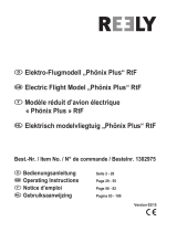
Mounting the wing servos / Monteren van beide vleugel servo’s /
Montage des servos d'aile / Montierung von die Flügelservos
fig. 1 fig. 2 fig. 3
Drill a hole off approx. 1,5mm in
the servo arm off the servo, see
fig. 1. Place the steering rod as
shown in fig. 2.
Cut off the origional lead of the
servo at approx. 3 cm and
solder the lead of the servo to
the pre-intalled servo extension
lead.
Take care off the polarity!
Glue the servo in the wing as
shown. Screw the kwiklink with
horn on the push rod thread.
Constrain the horn on the
horizontal fin with matching
screws. Cut off the excessif
thread from the upperside of the
wing. See fig. 3-4-5-6-7-8-9.
Boor een gaatje van ±1,5mm in
de servo-arm van de servo, zie
fig. 1. Plaats de stuurstang zoals
aangegeven in fig. 2.
Knip de originele draad van de
servo op ± 3cm door en soldeer
de draden van de servo aan de
reeds voorziene verlengkabels.
Let op de polariteit!
Verlijm de servo in de vleugel
zoals afgebeeld. Schroef de
kwiklink met stuurhoorn op de
schroefdraad. Bevestig
vervolgens de stuurhoorn op het
rolroer met bijbehorende
schroeven. Verwijder overtollige
schroefdraad aan de bovenzijde
van de vleugel. Zie fig. 3-4-5-6-
7-8-9.
Percez un trou de ±1,5mm dans
le bras servo pour le passage
de la commande, voir fig. 1.
Placez la tringlerie comme
montré dans la fig. 2.
Coupez le fil du servo à ±3 cm
et soudez ce fil à la rallonge
située dans l’aile.
Faites attention au polarité!
Collez le servo dans l’aile à
l’aide de scotch double face.
Vissez la chape dans la tige de
commande et placez le guignol
sur l’aileron. Percez les trous
d’amorçage et fixez les guignols
avec les vis prévues. Coupez si
nécessaire les vis trop longues.
Voir les fig. 3 à 9.
fig. 4
Bohren Sie eine Loch ca.
1,5mm in den Servoarm von
servo, sehen Sie Fig. 1.
Plazieren Sie die Lenkgestänge
wie in Fig. 2 gezeigt.
Schneiden Sie die
originalleitung des Servos an ca.
3 Zentimeter ab und löten Sie
die Leitung des Servos zu dem
Verlängerungskabel in dem
Flügel.
Achten Sie auf die Polarität!
Kleben Sie das Servo im Flügel
wie gezeigt. Schrauben Sie der
Gabelkopf auf die Stangen und
montieren Sie die Hörner auf
dem horizontalen Ruder mit
dem vorgesehene Schrauben.
Zerschneiden Sie das
überflußiges gewindeteil am
oberen Seite von den Flügel,
sehen Sie Fig. 3-4-5-6-7-8-9.

Piper Cub - 7
fig. 10 fig. 11
Mount the supplied
servoprotectors, see fig. 10-11.
Monteer de bijgeleverde
servobeschermer, zie fig. 10-11.
Montez les protections du servo
fournis, voir fig. 10-11.
Befestigen Sie die gelieferten
Servoabdeckung, sehen Sie Fig.
10-11.
Fixing the horizontal stabilizer / Bevestigen van het hoogteroer /
Fixation du stabilisateur horizontal / Befestigung von das Höhenruder
First you have to fix the wing on
top off the airplane, see fig. 12.
Mark the middle of the horizon-
tal stabilizer and make a 90°
angle on the rudder, see fig. 13-
14. Now you can mark two lines
approx. 12mm from the center
for positioning the stabilizer, see
fig. 15.
Place the stabilizer in the
fuselage as shown on fig. 16-17.
Take care! The stabilizer must
be perfectly horizontal to the
wing and fuselage.
Monteer eerst de vleugel, zie fig.
12.
Duidt het midden van het
hoogteroer aan en trek een
loodlijn, zie fig. 13-14. Zet nu op
± 12mm links en rechts een
puntje op de voorzijde van het
hoogteroer, zie fig. 15. Deze
aanduiding kan u gebruiken voor
het juist positioneren van het
hoogteroer.
Plaats het horizontale vlak in de
romp zoals op fig. 16-17
afgebeeld.
Let op! Deze moet perfect
horizontaal staan t.o.v. de
vleugel en de romp.
Montez l’aile (voir fig. 12). Vous
pouvez mettre une marque au
millieu du stabilisateur horizon-
tal. Marquez un angle de 90°
avec le stabilisateur, voir fig. 13-
14. Maintenant vous metrez
deux marques à ±12mm du
centre de la stabilisateur, voir
fig. 15. Utilisez ce marque pour
positioner le stabilisateur
horizontal.
Placez le stabilisateur sur le
fuselage comme montré sur les
fig. 16-17.
Attention! Le stabilisateur doit
être parfaitement parallèle à aile
et perpendiculaire au fuselage.
Nachdem Sie den Flügel auf
dem Rumpf befestigt haben
(sehen Sie fig. 12), können Sie
das mittle von Höhenruder
markieren. Machen Sie jetzt
einem 90° Winkel auf dem
Ruder, sehen Sie Fig. 13-14.
Markieren Sie an beide Seiten
auf ±12mm von das mitten von
das Ruder zwei marken, sehen
Sie Fig. 15. Diese Markierungen
können Sie jetzt gebrauchen
zum positionieren von das
Höhenruder.
Setzen Sie das Höhenruder in
dem Rumpf, wie auf Fig. 16-17
gezeigt.
Achtung! Das Höhenruder muß
am Flügel und der Rumpf
vollkommen horizon-
tal sein.
fig. 12 fig. 14fig. 13
fig. 15 fig. 16 fig. 17

8 - Piper Cub
Fixing the vertical fin / Bevestiging van het richtingsroer /
Fixation du dérive vertical / Befestigung von das Seitenruder
Glue the vertical fin in de pre-
formed slot of the fuselage.
Take care the vertical fin is in a
90° angle to the stabilizer, see
fig. 22.
Verlijm het vertikale vlak in de
voorgevormde sleuf van de
romp.
Zorg ervoor dat het richtingsroer
in een hoek van 90° staat t.o.v.
het hoogteroer, zie fig. 22.
Collez la dérive dans la fente
prédécoupée du fuselage.
Faites attention que celle-ci est
dans un angle de 90° avec le
stabilisateur, voir fig. 22.
Kleben Sie das Seitenruder
in die vorgeformtem Schlitz des
Rumpfs.
Achten Sie das das Sietenruder
in einem 90° Winkel
zum Höhenruder steht, sehen
Sie Fig. 22.
fig. 22
Fixing the tailwheel / Bevestigen van de staartwiel /
Fixer la béquille pour roulette / Befestigung von Hecksporn
Cut in the middle of the back of
the fuselage, see fig. 18.
Glue the tailskid and fix the
wheel as shown in fig. 19-20-21.
Snij in het midden van de
achterzijde van de romp, zie fig.
18.
Verlijm de staartsteun en
bevestig het wieltje zoals
afgebeeld op fig. 19-20-21.
Coupez l’entoilage au milieu de
la queue du fuselage, voir fig.
16.
Collez la béquille et fixez la roue
comme montré dans la fig. 19-
20-21.
Schneiden Sie mitten in der
Rückseite des Rumpfs, sehen
Sie Fig. 18.
Kleben Sie das
Hecksporn und befestigen Sie
das Rad, wie in Fig. 19-20-21.
fig. 18 fig. 19 fig. 20
fig. 21

Piper Cub - 9
Control linkage / Stuurstangen /
Tringlerie de commande / Gestänge
Screw the kwiklinks on the push
rods thread and connect the
horn as shown on fig. 25-26-27.
Cut off the excessif thread, see
fig. 28.
Take care! While mounting both
horns, the servo arm as well as
the rudder must be in the
neutral position.
Schroef de kwiklinks op de
schroefdraad en bevestig de
horn zoals afgebeeld op fig. 25-
26-27. Knip de overtollige
schroefdraad af, zie fig. 28.
Opgelet! Bij het bevestigen van
beide horns moet zowel de
servo-arm en het roer neutraal
staan.
Vissez les chapes sur les tiges
filetées et vissez les guignols
comme montré sur les fig. 25-
26-27. Coupez si nécessaire les
vis trop longues, voir fig. 28.
Attention! Tout en montant les
deux commandes, les bras de
servos ainsi que les gouvernes
doivent être en position neutre.
Schrauben Sie die Gabelköpfe
auf die Gestängen und
montieren Sie den Horn, wie auf
fig. 25-26-27 gezeigt.
Zerschneiden Sie das
überflußiges gewindeteil, sehen
Sie Fig. 28.
Achtung! Bei der Montierung
beider Horner, muß der
Servoarm sowie das Seitenruder
im Mittelstellung sein.
fig. 25 fig. 26
Mounting both servos in fuselage / Montage van beide servos in de romp /
Montage des deux servos dans le fuselage / Montierung beide Servos in Rumpf
fig. 23
fig. 24
Mount the servo in the fuselage.
Use the wooden mounting stick
6x6mm delivered in the box.
See fig. 23-24.
Drill a hole off approx. 1,5mm in
both servo horns to connect the
steering rods.
Monteer de servo’s in de romp.
Gebruik hierbij het bijgeleverde
houten bevestigingsbalkje van
6x6mm. Zie fig. 23-24.
Boor een gaatje van ± 1,5mm in
beide servo armen voor het
bevestigen van de stuurstangen.
Fixez les servos dans le
fuselage. Utilisez le longeron
6x6mm fournis dans la boîte.
Voir fig. 23-24.
Forez un trou de ±1,5mm dans
les deux bras de servo pour
connecter les tringlerie de
commande.
Befestigen Sie die Servo im
Rumpf. Gebrauchen Sie das im
baukasten mitgelieferte holz
Servobefestigungteil 6x6mm.
Bringen Sie die Stangen auf den
Servoarmen an. Sehen Sie Fig.
23-24.
Bohren Sie ein Loch von ca.
1,5mm in beiden Servoarmen
für befestigung des
Stosselstangen.
fig. 27
fig. 28

10 - Piper Cub
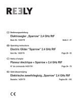
Mounting the landinggear / Monteren van het landingsgestel /
Montage du train d’atterrisage / Montierung von das Fahrwerk
Fix the landinggear by using
copper thread. When every item
is placed in the wright position
you should solder the
landinggear, see fig. 35-36-37.
Slide the 2 copper tubes over
the landinggear where the
wheels will be attached. Fix the
wheel on the copper tube, see
fig. 38-39-40.
Mount the landinggear on the
bottom side off the fuselage by
means of 2 retainers on the
foreseen places.
Stel het volledige landingsgestel
samen door gebruik te maken
van bijgeleverde koperdraad en
hulzen. Wanneer alles in de
juiste positie staat dient men het
geheel te solderen, zie fig. 35-
36-37.
Monteer de wielen op de
koperen huls en fixeer ze, zie
afbeelding 38-39-40.
Bevestig het landingsgestel aan
de onderzijde door middel van
de 2 bijgeleverde bevestigings-
stukken.
Fixez le train d’atterrissage en
utilisant du fil de cuivre. Une fois
que chaque élément est placé
dans la bonne position, vous
pouvez souder, voir fig. 36-37.
Glissez les 2 tubes de cuivre sur
le train d’atterrissage où les
roues seront jointes. Fixez la
roue sur le tube de cuivre, voir
fig. 38-39-40.
Montez le train d’atterrissage du
côté inférieur du fuselage au
moyen de 2 arrêtoirs sur les
endroits prévus.
Verwenden Sie Messing Draht
um das Fahrwerk zusammen zu
stellen. Wenn jedes Einzelteil in
die korrekte position gelegt
wird, können Sie das
Landungsfahrwerk löten, sehen
Sie fig. 36-37.
Schieben Sie die 2 Messing
Rörchen über das
Landungsfahrwerk, wo die
Räder angebracht werden.
Befestigen Sie das Rad auf dem
Messing Rörchen, sehen Sie fig.
38-39-40.
Befestigen Sie das
Landungsfahrwerk an der
unteren Seite vom Rumpf auf
den vorgesehenen Plätzen
mittels 2 Halter.
fig. 36 fig. 37fig. 35
fig. 39 fig. 40fig. 38

Piper Cub - 11
Mounting speedcontroller and motor / Monteren van regelaar en motor /
Monter le régulateur de vitesse et le moteur / Montierung von dem Drehzahlregler und den motor
Solder the speedcontroller to
the motor and mount as shown
on fig. 35-36. Attach the motor
with 4 screws, see fig. 37-38.
Soldeer de regelaar aan de
motor en monteer zoals
afgebeeld, zie fig. 35-36.
Bevestig de motor met 4 vijzen,
zie fig. 37-38.
Soudez le régulateur de vitesse
au moteur et montez-le comme
sur les fig. 35-36. Fixez le
moteur avec 4 vis, voir fig. 37-
38.
Löten Sie dem Drehzahlregler
am Motor und montieren Sie es
wie auf Fig. 35-36 gezeigt.
Befestigen Sie den Motor mit 4
Schrauben, sehen Sie Fig. 37-
38.
fig. 35 fig. 36
fig. 37
fig. 38
Preparing the cowling / Voorbereiden van de motorkap /
Préparer le capot moteur / Vorbereiten von die Motorhaube
Make a hole of approx. 8mm in
the cowling for the engine axle
and paint it, see fig. 39-40-41.
Frees een gaatje van 8 mm ter
hoogte van de motoras en verf
het geheel, zie fig. 39-40-41.
Faites un trou de ±8mm pour le
passage de l’axe de moteur, voir
fig. 39-40-41.
Bohren Sie ein Loch von ±8mm
in die Motorhaube, für die
dürchfürung der Motorachse
und farben Sie die Motorhaube,
sehen Sie Fig. 39-40-41.
fig. 39
fig. 46
fig. 41fig. 40

12 - Piper Cub
Mounting the cowling and propeller / Moteren van de motorkap en propeller /
Montage du capote moteur et l’hélice / Montierung von Motorhaube und Propeller
Place the cowling in position
and fix the propeller. Screw the
cowling on the fuselage, see fig.
42-43.
Plaats de motorkap in positie en
moteer de propeller. Schroef
vervolgens de motorkap vast,
zie fig. 42-43.
Placez le capot en position et
fixez l’hélice. Vissez le capot sur
le fuselage, voir fig. 42-43.
Setzen Sie die Motorhaube in
Position und befestigen Sie den
Propeller. Schrauben Sie die
Motorhaube auf dem Rumpf,
sehen Sie Fig. 42-43.
fig. 42 fig. 43
Mounting the receiver and the battery pack / Monteren van de ontvanger en het batterijpack /
Monter le récepteur et la batterie / Montieren von den Empfänger und die Batterie
Place the (min. 5 ch) receiver
under the servos and install 2
extension leads for the connec-
tion of the horizontal fin, see fig.
44.
Place the battery as shown on
fig. 44.
Plaats een (min. 5 kanaals)
ontvanger onder de servos en
voorzie 2 verlengkabels voor het
aansluiten van de rolroeren, zie
fig. 44.
Plaats de batterij zoals
afgebeeld in fig. 44.
Placez le (min. 5 ch) récepteur
sous les servos et installez 2
cables d’extension pour
connecter le guignol sur les
ailerons, voir fig. 44.
Placez les batteries comme
montré aux la fig. 44.
Plazieren Sie dem (min. 5 Kan)
Empfänger unter die Servos und
bringen Sie 2 Verlängerungs-
kabel ein für die befestigung des
Querruder, sehen Sie fig. 44.
Plazieren Sie die Batterie wie
gezeigt auf Fig. 44.
fig. 44
Fixing the cockpit windows / Bevestiging van de cockpit vensters /
Fixation du pare-brise et les fenêtres laterals / Befestigung von die Frontscheibe und Seitenfenster
Glue or tape the front and the 2
side windows as shown on fig.
45-46.
Bevestig de voorste en de 2
zijvensters met lijm of kleefband
zoals afgebeeld op fig. 45-46.
Collez la pare-brise et les 2
vitres de coté avec colle ou
Scotch comme montré sur les
fig. 45-46.
Verkleben Sie die vordere und 2
Seitliche Fenster mit Klebstoff
oder Klebeband wie gezeigt auf
Fig. 45-46.
fig. 45
fig.46

Piper Cub - 13
Fixing the wing / Bevestiging van de vleugel /
Fixation de l’aile / Befestigung von die Flügel
Fix the wing onto the fuselage
as shown (fig. 47).
Insert the wingposts in the pre-
fixed holes in the fuselage and
the wing, see fig. 48-49.
Bevestig de vleugel op de romp
zoals getoond (fig. 47).
Bevestig de vleugelsteunen in
de daarvoor voorziene gaatjes in
de romp en de vleugels, zie fig.
48-49.
Fixez à l’aide de la vis en nylon
l’aile sur le fuselage comme
montré sur l’image (fig. 47).
Montez les mâts de haubans
dans les trous prévus- dans le
fuselage et l’aile, voir fig. 48-49.
Befestigen Sie den Flügel auf
den Rumpf, wie
auf der Abbildung gezeigt
(fig.47).
Montieren Sie die Flugelstreben
im Rumpf und Flügel, sehen Sie
Fig. 48-49.
fig. 47 fig. 48 fig. 49
Straighten covering / Bijtrekken van de bespanning /
Amméliorez le recouvrement / Bearbeiten von Bespannfolien
When necessary you can heat
the covering of the wing and
fuselage.
Indien nodig kan u de
bespanning van de vleugel en
de romp met een strijkbout
bijtrekken.
Ci nécessaire le recouvrement
de l’aile et du fuselage peut être
ammélioré à l’aide d’un fer à
repasser.
Wenn erforderlich können Sie
die Bespannfolien von den
Flügel und Rumpf mit ein
Bügeleisen nach bearbeiten.
fig. 50

14 - Piper Cub
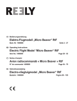
Decals / Decals /
Autocollants / Dekor

16 - Piper Cub
© Copyright PROTECH
• Your kit is warranted against defects
in material and workmanship.
• This warranty does not apply to any
component parts, which have been
improperly installed, handled,
abused, damaged, modified and
used.
• De kit heeft een garantie voor
materiaalfouten en fabrieksfouten.
• Deze garantie geldt niet voor
onderdelen die niet goed zijn
geïnstalleerd, behandeld, mishandeld,
beschadigd, aangepast en gebruikt.
• Ihr Installationssatz wird gegen
Defekte im Material und in der
Kunstfertigkeit gewährleistet.
•
Diese Garantie trifft nicht auf
irgendwelche Bestandteile zu, die
unsachgemäß installiert worden,
angefaßt worden, mißbraucht worden,
beschädigt worden, geändert worden
und benutzt worden sind.
• Votre kit est garanti contre les défauts
de matériaux et de main d’oeuvre
• Cette garantie ne s’applique pas aux
composants qui ont été incorrecte-
ment montés, manipulés, modifiés et
utilisés ou qui ont été endommagés.
Limited warranty / Beperkte garantie /
Begrenzte garantie / Garantie limitée
Ready for take off / Uw model is vliegklaar /
Votre modèle est prêt à voler / Ihr modell ist fertig zu fliegen
/