Page is loading ...

13
PLEASE NOTE: Because of the various mounting applications, no mounting hardware is
provided with the GTO Automatic Gate Lock. All necessary mounting hardware can be obtained
from your local hardware store; all other hardware is provided.
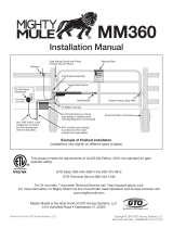
This manual shows two examples of the most common installations, and should provide insight
into most other applications. If you have any questions during installation, please call
(800) 543-1236 for technical support.
Installation Manual
RB909 rev-10/19/07
© GTO, Inc. 2007
AUTOMATIC
GATE LOCK
®
IMPORTANT: Before you install the automatic gate lock be sure your gate is level, moves freely on
its hinges, and does not bind or drag against the ground.
For more information on GTO's full line of automatic gate openers and access controls visit our website at www.gtoinc.com
Printed in China for GTO, Inc.

1
The installation has two parts:
(1) Mounting The Lock and Lock Receiver
(2) Connecting the Control Boards
Once you have the necessary mounting hardware, you can begin the installation.
Before You Start...
For the GTO Automatic Gate Lock to work properly, the gate must close firmly against a positive stop and
engage the lock catch against the lock receiver. Achieving optimal closure may require slight adjustments to
the gate opener settings.
Installing the lock with the Gate Opener may require resetting closed limits and changes to the stall force.
See Setting the Gate Closed Position in your Gate Opener Installation Manual for information on these
adjustments.
Set the limits so that the arm holds the gate snug against the stop in the closed position. IMPORTANT: You
may need to spray the locking mechanism with silicone spray initially to help the latch move freely.
If you are installing the lock on a Push-to-Open gate (gate opens out), the lock must be installed on the outside
of the gate. Depending upon the installation, the gate post may need to be "pocketed" to accommodate the
lock receiver or you may want to purchase the column mount receiver. Contact the GTO Technical Service
Department at (850) 575-4144 for assistance if needed.
NOTE: Positive stops are required for dual gate applications.
AUTOMATIC
GATE LOCK
®
D
E
F
G
H
I
J
K
L
M
C
3½”
¼” Diameter
Optional
Column Mount Receiver
433IH (not included)
B
2”
2¾”
A
2”
5½”
8½”
Be sure you have all the parts:
A - Lock with 20' of low voltage wire
B - Lock Receiver
C - Clevis Pin
D - Locking Cap
E - Lock Board Battery Lead Wires
F - White Wire
(motor lead to lock board)
G - Lock Control Board (Lock PCB)
H - 2 Double Spade Tongue terminals
I - 6 nylon cable ties
J - Wire Connector
K - Lock Keys (for manual release)
L - Lock Decal
M - Optional Column Mount Receiver
433IH (not included)
What else do you need?
Mounting hardware is not included. Read these instructions completely and review the installation examples to
determine the mounting hardware required for your application.
NOTE: The GTO Lock is designed to use mounting hardware up to
5
/16" in diameter. For a more secure installation,
use lock washers and lock nuts on all mounting hardware.
For most IRON or ALUMINUM TUBE gates you will need:
Carriage bolts, washers, and nuts for the lock and receiver. (see Illustration B, page 3)
For most CHAIN LINK gates you will need:
U-Bolts, saddles or carriage bolts, washers and nuts for the lock.
Bolts, washers, and nuts for the receiver. (see Illustration C, page 3)

2
Installing The Gate Lock
Illustration A
Lock and receiver must be level
and aligned with opener.
500
500
Step 1: With the gate in the closed position, determine the best location for the lock and lock receiver. The lock
and receiver must be level and aligned with the opener. Also, the lock should have a solid surface or
cross member to provide stability.
Step 2: Clamp receiver and lock together (with receiver pin hole and lock slot aligned) against the gate post,
mark their positions to drill receiver holes (see Illustration B and C, page 3). The receiver must be
mounted with carriage bolts, not U-bolts, to allow lock to seat properly. Fasten the receiver to the gate
post.
Step 3: Hold latch open with key to operate gate and check closed limit and lock alignment. Drop pin in receiv-
er but don't put the cap on. Recheck the lock's position and alignment, then mark its position for drilling
holes.
Step 4: Drill the holes on gate supports through the slots in the lock bracket. U-bolts and saddles can be used
to mount the lock on chain link gate supports. Secure the lock to the gate. Install clevis pin and locking
cap by placing clevis pin through slots in lock receiver and hammering the clevis pin into the locking
cap (see Illustration D), secure the lock bracket and check the alignment again.
NOTE: The Automatic Gate Lock can be installed on single and dual gate systems. Use the appropiate
instructions for the system you have - SINGLE GATE (below) or DUAL GATES (page 4).
Turn power switch OFF on the bottom of the control box. Disconnect gate opener by removing hairpin
clip and clevis pin from the gate bracket end of the opener. Disconnecting the opener will allow the gate
to swing freely during installation of the gate lock.
Single Gate Installation

3
Clevis Pin
Receiver
Locking Cap
Lock
U-bolts, saddles & nuts
(not provided)
Added cross member
to support lock from
force of slammimg shut
Remember to check the alignment and mark positions before
drilling holes in fence post .
Illustration B
Iron or Aluminum Tube Fence and Gate Installation
Illustration C
Chain Link Fence and Gate Installation
Illustration D
Locking Cap
Assembly
Clevis Pin
Receiver
Locking Cap
GTO Automatic
Gate Lock
Carriage bolts, washers, and nuts
(not provided; size of
fasteners depends on the gate)
Remember to check the alignment and mark positions
before drilling holes in fence post and gate.

4
SET
LIMIT
LEARN
TRANSMITTER
1
ON
2 3 4 5 6 7
MODES
ON
OFF
1 2 3 4 5 6 7
1
ON
2 3 4
DUAL
MODES
ON
OFF
1 2 3 4
DIP switches
1 2 3 4
ON
OBSTRUCT
SENS.
PULL/PUSH
SEQ1
SNGL/DUAL
SEQ2
LEARN
DIP switches
MIN MAX
Turn power switch OFF on the bottom of the control box. Disconnect gate openers by removing hairpin clip and
clevis pin from the gate bracket end of the openers. Disconnecting the openers will allow the gates to swing freely
during installation of the gate lock.
Dual Gate Installation
IMPORTANT: To use the gate lock on a dual gate system, the gate sequencing must be set so the MASTER GATE
opens first and closes last, and the gate lock has to be mounted on the MASTER GATE and the lock receiver is
mounted on the SLAVE GATE. The slave gate requires a positive stop. If your gates are not sequenced in a manner
that works like this, you'll have to change the sequencing DIP switches on your gate opener control board. Follow
the instructions in your gate opener installation manual for programming dual gate sequencing.
The diagrams below will show how most dual GTO/PRO
®
and Mighty Mule
®
gate sequencing is programmed. If
your gate opener control board is different form these shown, please contact GTO Technical Service at 1-800-543-
1236 for additional information.
First Operator opens first, Second Operator closes first
SEQ1 = OFF SEQ2 = ON
If SEQ1 is set to OFF, and SEQ2 is set to ON, the FIRST
OPERATOR will open first, and the SECOND OPERATOR
will close first.
Master opens 2 secs before slave, Slave closes 8 secs before
master.
Switch 1 = ON Switch 2 = OFF Switch 3= ON
If Switch 1 is set to ON, Switch 2 is set to OFF and
Switch 3 is set to ON, the MASTER OPERATOR will
open first, and the SLAVE OPERATOR will close first.
Master opens 2 secs before slave, Slave closes 8 secs before
master.
Switch 4= OFF
If Switch 4 is set to OFF, the MASTER OPERATOR will
open first, and the SLAVE OPERATOR will close first.
Master opens 2 secs before slave, Slave closes 8 secs before
master.
Switch 2 = OFF Switch 3 = ON Switch 4 = OFF
If Switch 2 is set to off and Switch 3 is set to on the MASTER
will open first and the SLAVE operator will close first. Switch 4
must be set to LOCK MODE to avoid damaging circuit board
For Mighty Mule
®
FM502, GTO/PRO
®
3000
and GTO/PRO
®
4000 Dual Gate Openers
NOTE: In a DUAL GATE INSTALLATION the gate opener on the same side of the driveway as the control box is
known as the MASTER GATE OPENER and that gate is refered to as the MASTER GATE. Conversly the gate opener
on the other gate is refered to as the SLAVE GATE OPENER and the gate is refered to as the SLAVE GATE.
For Mighty Mule
®
FM702, GTO/PRO
®
1000
and GTO/PRO
®
2000 Dual Gate Openers
Mighty Mule
®
350 Control Board Gen - 3 (Blue) Control Boards
1
ON
2 3 4
CHARGING
RF
PULL-PUSH
MODE1
MODE2
LOCK/BEACON
CLOSE TIME
SET
LIMIT
LEARN
REMOTE
1 2 3 4
ON DIP
STATUS
LEARN RMT
LEARN
MAST LIMIT
LEARN
SLV LIMIT
S3
S4
S2
OFF
SOFT START OFF
WARNING OFF
OPEN PULL
SLV OPEN DLY.
MODE1 OFF
MODE2 OFF
ON
ON
PUSH
SIMULT.
ON
ON
120 MIN MAX
AUTO CLOSE TIME STALL FORCE

5
Step 1: With the gate in the closed position, determine the best location for the lock and lock receiver. The lock
and receiver must be level and aligned with the opener. Also, the lock should have a solid surface or
cross member to provide stability.
Step 2: Clamp receiver and lock together (with receiver pin hole and lock slot aligned) to the gates, mark their
positions to drill holes (see Illustration E and F, page 6). The receiver must be mounted on the SLAVE
GATE with carriage bolts, not U-bolts, to allow lock to seat properly.
Step 3: Recheck the lock's position and alignment. Hold latch open with key and operate gate. Drill the holes on
gate supports through the slots in the lock bracket. U-bolts and saddles can be used to mount the lock
on chain link gate supports. Secure the lock to the MASTER GATE. Install clevis pin and locking cap
by placing clevis pin through slots in lock receiver and hammering the clevis pin into the locking cap
(see Illustration G), secure the lock bracket and check the alignment again.
With the sequencing set correctly follow the steps and diagrams below to mount the lock to the gates.
Lock and receiver must be level and aligned with opener.
Hold latch open with key to operate gate.
Receiver pin hole and lock slot must line up.
MASTER GATE
SLAVE GATE
(second gate opener) (first gate opener)
500
500
500

6
Locking Cap
Assembly
Clevis Pin
Receiver
Locking Cap
Lock
U-bolts, saddles & nuts
(not provided)
Added cross member
to support lock from
force of slammimg shut
Remember to check the alignment and mark positions before
drilling holes in fence post .
Illustration F
Clevis Pin
Receiver
Locking Cap
GTO Automatic
Gate Lock
Carriage bolts, washers, and nuts
(not provided; size of
fasteners depends on the gate)
Remember to check the alignment and mark positions
before drilling holes in fence post and gate.
Illustration E
Illustration G

7
RED Wire To Battery
Positive (+) Terminal
RED Wire From Lock
BLACK Wire From Lock
WHITE Wire to
BLACK on Operator Terminal
BLACK Wire To Battery
Negative (–) Terminal
1
2
345
Lock Board
Double Spade Connector
Double Spade Connector
RED Wire To Battery
Positive (+) Terminal
BLACK Wire To Battery
Negative (–) Terminal
12 Volt Battery
Double Spade
Tongue Connectors
2000XL,3000XL,4000XL
Control Board
Double Spade Connector
Double Spade Connector
RED Wire From Lock
BLACK Wire From Lock
SOLAR
or
18 VAC
ORGBLUEWHTGRNBRN
SLAVE INPUT
LOCK
GTOAUX
GTO
TRANSF
LOCK
PWR
AUX
RLY
POWER
INPUTS
CONTROL
OUTPUTS
SLAVE CAB
Wiring the Lock to Mighty Mule PRO-SW2000XL, PRO-SW3000XL, and
PRO-SW4000XL Gate Opener Control Boards
* Place a dab of petroleum
jelly on the terminal con-
tacts to prevent corrosion.
Lock Board
Wiring Chart

8
Step 1. Turn control box power switch OFF and unplug the transformer or disconnect the solar panel. Remove
control box cover and disconnect battery lead wires from the battery terminals before wiring the lock
board to the opener control board.
Step 2. Connect the WHITE wire (included) to Terminal #1 on the lock board. Connect the RED battery lead
wire (included) to Terminal #5 on the lock board.
Step 3. Attach the RED control board battery lead wire to one spade tongue on a double spade tongue connector
(included). Attach the BLACK control board battery lead wire to one spade tongue on the other double
spade tongue connector (included).
Step 4. Pull RED and BLACK wires from gate lock through the strain relief and into the control box. Attach
BLACK wire to Terminal #3 on lock board. Attach RED wire to Terminal #4 on lock board (see Lock
Board Wiring Chart below).
Step 5. Attach RED lock board battery lead wire to the double spade tongue terminal with the RED control
board lead wire. Attach the BLACK lock board battery lead wire to the double spade tongue connector
with the BLACK control board Lead Wire.
Step 6. Connect the WHITE wire from the lock board directly to the MASTER OPERATOR terminal block
along with the power cable wire from the opener arm. Connect the WHITE wire to the RED terminal
for a Pull-to-Open installation or connect WHITE wire to the BLACK terminal for a Push-to-Open
installation (see illustration on page 9).
Step 7. Reconnect opener to gate bracket. Connect the BLACK Battery lead wire (included) to Terminal #2 on
the lock board. (See Lock Board Wiring Chart below). Connect RED wires (with double spade tongue
terminal) to POSITIVE (+) battery terminal and the BLACK wires (with double spade tongue terminal)
to the NEGATIVE (–) battery terminal. Plug the transformer in or rewire the solar and turn the control
box power switch ON. Test opener and lock to make sure it functions properly and make adjustments if
necessary.
Wiring the Lock to Gate Opener Control Boards
MM500/502, PRO-SW3000, PRO-SW4000
RED Wire To Battery
Positive (+) Terminal
RED Wire From Lock
BLACK Wire From Lock
WHITE Wire to
RED on OperatorTerminal
Lock Board
BLACK Wire To Battery
Negative (–) Terminal
1
2
345
Time Adj
* Place a dab of petroleum
jelly on the terminal con-
tacts to prevent corrosion.
Lock Board
Wiring Chart
NOTE: It is recommended that the time adjustment knob is turned all the way to the right.

9
12 Volt Battery
Double Spade
Tongue Connectors
RED Wire To Battery
Positive (+) Terminal
RED Wire From Lock
BLACK Wire From Lock
WHITE Wire to
BLACK on Operator Terminal
BLACK Wire To Battery
Negative (–) Terminal
1
2
345
Lock Board
Double Spade Connector
Double Spade Connector
WHITE Wire to Operator Board
Master Operator RED Terminal
RED Wire To Battery
Positive (+) Terminal
RED Wire From Lock
BLACK Wire From Lock
BLACK Wire To Battery
Negative (–) Terminal
1
2
345
Lock Board
Time Adj
MASTER OPERATOR
POWER CABLE
RECEIVER
SWITCH
MASTER INPUTS
GRN WHT BLUE BRN ORG RED BLK COM COM
CYCLE
CLOSE
SAFETY
EXIT/
OPEN
SHADOW
LOOP
CLOSE
EDGE
OPEN
EDGE
BLKGRN RED
STALL FORCE
M
I
N
M
A
X
GRN
WHT
BLUE
BRN
ORG
BLK
RED
500/502 and 3000/4000
Control Board
Double Spade Connector
Double Spade Connector
Pull-to-Open Application
NOTE: For Push-to-Open applications connect lock board
white wire to the operator board BLK master terminal
Wiring the Lock to Mighty Mule 500/502 and GTO/PRO SW-3000 and SW-4000
Gate Opener Control Boards
Manual Lock Release:
The GTO Automatic Gate Lock is keyed for manual release.
Should the electronic release be disabled for any reason, simply
use the key to manually open the lock.
* Place a dab of petroleum
jelly on the terminal con-
tacts to prevent corrosion.
Lock Board
Wiring Chart

10
Step 1. Turn control box power switch OFF and unplug the transformer or disconnect the solar panel. Remove
control box cover and disconnect battery lead wires from the battery terminals before wiring the lock
board to the opener control board.
Step 2. Connect the WHITE wire (included) to Terminal #1 on the lock board. Connect the RED battery lead
wire (included) to Terminal #5 on the lock board.
Step 3. Attach the RED control board battery lead wire to one spade tongue on a double spade tongue connector
(included). Attach the BLACK control board battery lead wire to one spade tongue on the other double
spade tongue connector (included).
Step 4. Pull RED and BLACK wires from gate lock through the strain relief and into the control box. Attach
BLACK wire to Terminal #3 on lock board. Attach RED wire to Terminal #4 on lock board (see Lock
Board Wiring Chart below).
Step 5. Attach RED lock board battery lead wire to the double spade tongue terminal with the RED control
board lead wire. Attach the BLACK lock board battery lead wire to the double spade tongue connector
with the BLACK control board Lead Wire.
Step 6. Connect the WHITE wire from the lock board directly to the FIRST OPERATOR terminal block along
with the power cable wire from the opener arm. Connect the WHITE wire to the BLACK terminal for
a Pull-to-Open installation or connect WHITE wire to the RED terminal for a Push-to-Open installation
(see illustration on page 11).
Step 7. Reconnect opener to gate bracket. Connect the BLACK Battery lead wire (included) to Terminal #2 on
the lock board. (See Lock Board Wiring Chart below). Connect RED wires (with double spade tongue
terminal) to POSITIVE (+) battery terminal and the BLACK wires (with double spade tongue terminal)
to the NEGATIVE (–) battery terminal. Plug the transformer in or rewire the solar and turn the control
box power switch ON. Test opener and lock to make sure it functions properly and make adjustments if
necessary.
Wiring the Lock to Gate Opener Control Boards
FM700, PRO SW-1000, PRO-SW2000, PRO-SL1000, PRO-SL2000
RED Wire To Battery
Positive (+) Terminal
RED Wire From Lock
BLACK Wire From Lock
WHITE Wire to
BLACK on OperatorTerminal
Lock Board
BLACK Wire To Battery
Negative (–) Terminal
1
2
345
Time Adj
* Place a dab of petroleum
jelly on the terminal con-
tacts to prevent corrosion.
Lock Board
Wiring Chart
NOTE: It is recommended that the time adjustment knob is turned all the way to the right.

11
Wiring the Lock to Mighty Mule FM-700/702 and GTO/PRO 1000 and 2000
Gate Opener Control Boards
12 Volt Battery
Double Spade
Tongue Connectors
15 15
DER
KLB
NRG
GRO
LB U
DER
KLB
NRG
GRO
LB U
FIRST OPERATOR SECOND OPERATOR
DER
KCALB
NEERG
EGNARO
LB
EU
DER
KCALB
NEERG
EGNARO
LB EU
Power Cable
from First Operator
RED Wire T o Battery
Positive (+) Terminal
RED Wire From Lock
BLACK Wire From Lock
WHITE Wire to
BLACK on Operator Terminal
BLACK Wire T o Battery
Negative (–) Terminal
1
2
345
Lock Board
Double Spade Connector
Double Spade Connector
WHITE Wire to
Operator Board
BLK First Operator
Terminal
RED Wire T o Battery
Positive (+) Terminal
RED Wire From Lock
BLACK Wire From Lock
BLACK Wire T o Battery
Negative (–) Terminal
1
2
345
Lock Board
Time Adj
Pull-to-Open Application
NOTE: For Push-to-Open applications connect lock board
white wire to the operator board RED first operator terminal
* Place a dab of petroleum
jelly on the terminal con-
tacts to prevent corrosion.
Lock Board
Wiring Chart

12
Limited One Year Warranty:
GTO, Inc. • 3121 Hartseld Road • Tallahassee, Florida 32303 • www.gtoinc.com
GTO, Inc., gate opener accessories are warranted by the manufacturer against defects in workmanship for a period of one (1) year from
the date of purchase, provided recommended installation procedures have been followed.
In the case of product failure due to defective material or manufacturer workmanship within the one (1) year warranty period, the ac-
cessory will be repaired or replaced (at the manufacturer's option) at no charge to the customer, if returned freight prepaid to GTO, Inc.
3121 Hartsfield Rd., Tallahassee, FL 32303.
IMPORTANT: Call (800) 543-1236 for a Return Goods Authorization (RGA) number before returning accessory to factory. Products
received at the factory without an RGA will not be accepted. Replacement or repaired parts are covered by this warranty for the re-
mainder of the one (1) year warranty period or six (6) months, whichever is greater. GTO, Inc. will pay the shipping costs (equivalent
to United Parcel Service ground rate) for items repaired under warranty.
The manufacturer will not be responsible for any charges or damages incurred in the removal of the defective parts for repair, or for the
reinstallation of those parts after repair. This warranty shall be considered void if damage to the product(s) was due to improper instal-
lation or use, connection to an improper power source, or if damage was caused by lightning, wind, fire, flood, insects, or other natural
agent.
After the one (1) year warranty period, GTO, Inc. or one of its authorized service centers will make any necessary repairs for a nominal
fee. Call GTO at (800) 543-1236 for more information. This warranty gives you specific legal rights, and you may also have other
rights which may vary from state to state. This warranty is in lieu of all other warranties, expressed or implied. NOTE: Verification of
the warranty period requires copies of receipts or other proof of purchase. Please retain those records.
IMPORTANT:
For the optimum service and safety, find the ideal obstruction
sensing setting for your gate opener. Depending on the weight of your gate, the ideal
setting will be just enough to move your gate without self-obstruction (stopping or re-
versing due to its own weight), yet sensitive enough to reverse and stop when it meets
with an obstruction such as a car. See the GTO Installation Manual for information on
obstruction settings.
NOTE: Be sure your gate moves freely on its hinges without binding or dragging.
Troubleshooting
If lock hangs up and does not latch properly try the following steps before contacting Technical Support:
- Reset closed position limit so gate is snug against stop plate
- Lubricate latch with silicone spray to help latch to operate freely
- Check alignment of lock by using the key to hold the latch open while operating the gate opener
If lock still does not operate properly contact the GTO Technical Suppport Department:
Hours: MON - FRI 8:00AM - 7:00PM (ET)
(800) 543-1236
(850) 575-4144
/