Page is loading ...

for GTO Automatic Gate Openers
GTO, Inc. • 3121 Hartsfield Road • Tallahassee, Florida 32303 • (850)575-0176 • Fax (850)575-8912 • www.gtoinc.com
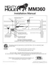
A. Solar Panel
B. #2 Lag Screws (4)
C. Pipe Clamp (4)
D. Curved Pipe
E. 1/4" Nuts (4)
F. 1/4" x 1" Bolt (4)
Tools Required :
• Flat blade screwdriver
• 7/16" open end wrench
Parts Included:
GTO, Inc., 5 watt solar panels are warranted by the manufacturer against defects in workmanship for a period of two (2) year from the date of purchase,
provided recommended installation procedures have been followed.
In the case of product failure due to defective material or manufacturer workmanship within the two (2) year warranty period, the accessory will be repaired
or replaced (at the manufacturer's option) at no charge to the customer, if returned freight prepaid to GTO, Inc. 3121 Hartsfield Rd., Tallahassee, FL 32303.
IMPORTANT: Call (850)575-0176 or fax (850)575-8912 for a Return Goods Authorization (RGA) number before returning accessory to factory. Products
received at the factory without an RGA will not be accepted. Replacement or repaired parts are covered by this warranty for the remainder of the two (2)
year warranty period. GTO, Inc. will pay the shipping charges for return to the owner of items repaired under warranty.
The manufacturer will not be responsible for any charges or damages incurred in the removal of the defective parts for repair, or for the reinstallation of
those parts after repair. This warranty shall be considered void if damage to the product(s) was due to improper installation or use, connection to an improper
power source, or if damage was caused by lightning, wind, fire, flood, insects, or other natural agent.
After the two (2) year warranty period, GTO, Inc. or one of its authorized service centers will make any necessary repairs for a nominal fee. Call GTO at
(850)575-0176 for more information. This warranty gives you specific legal rights, and you may also have other rights which may vary from state to state.
This warranty is in lieu of all other warranties, expressed or implied. NOTE: Verification of the warranty period requires copies of receipts or other proof of
purchase. Please retain those records.
Limited Two Year Warranty
A
B
C
F
C
E
D
RB905 … rev-7/1/98
© 1997 GTO, Inc.
Solar Panel
Installation Manual
5 Watt (300 ma)
NOTE: Maximum of 3 panels w/ Mighty Mule, GTO/PRO1000
Maximum of 4 panels w/ GTO/PRO1800
Maximum of 8 panels w/ GTO/PRO2000 and GTO/PRO SL-1000
19
3
/
8
"x 8
1
/
2
"

Solar Panel Installation
Step 1: Slide the 1/4" bolts (F) into each channel, position the
pipe (D) between the bolts and place two clamps (C) over the
curved pipe onto the bolts. Secure with the 1/4" nuts (E).
HINT: If the solar panel must be placed more than 8 ft.
from the control box (but less than 250 feet away), use
stranded, 16 gauge, direct burial, low-voltage wire (see
Accessory Catalog). Do not use telephone wire or any
solid core wire.
IMPORTANT: the solar panel must be positioned facing south, in an open area away from
shade, and should receive at least 8 hours direct sunlight for a full charge.
HINTS for Obtaining Maximum Output from Your Solar Panel
1. Place the panel facing south, where full sun will strike its face throughout the day (minimum 8 hours).
2.
Mount the panel using the curved pipe provided to maintain the proper angle to the sun.
3. For optimal efficiency wipe the face of the panel frequently with a soft, damp cloth.
The output of the Solar Panel is variable during the day, depending on the intensity of the sun and the angle
of the rays striking the panel. The output may vary from a few millivolts to as much as 20 volts. To check
the output simply disconnect the solar panel leads from the control board and connect directly to a D.C.
voltmeter. In bright sunlight the panel output should read at least 18 volts D.C.
Step 2: Determine the site for installation of the solar panel. It is important
to install the solar panel facing due south. The curved pipe maintains the
proper angle to the sun. Secure the solar panel assembly to wooden post or
fence using two pipe clamps (C) and #2 lag screws (B) as shown in illustra-
tion. If your fence post is metal, you will need alternative hardware not
provided, (i.e. u-clamps or metal screws).

Step 3:
Determine which operator and/or control board you have and follow instructions for wiring the solar panel.
Feed the free end of the solar panel wires up through the strain
relief and attach them to the red and black leads in the junction box.
Strain
Relief
Operator
Control
Board
(Phase 8)
Wire nuts
Mighty Mule & GTO/PRO
Phase 8-Control Board
GTO AC
ADAPTOR
SOLAR
PANEL
Switch to solar panel
Accessory Harness
Wire from solar Panel
B
L
A
C
K
R
E
D
Connecting the Solar Panel to the GTO/PRO 1000, GTO/PRO SL-1000, GTO/PRO 1800, GTO/PRO 2000 and
the new Mighty Mule Control Boards – these control boards have green terminal blocks at the bottom of the
board for connecting wires.
Feed the free end of the solar panel wires up through the strain relief on the control box and attach them to the
"power in" terminal block marked SOLAR.
Connecting the Solar Panel to the "Phase 8" Control Board. These boards have a plug with accessory leads
instead of terminal blocks.
Attach RED solar panel wire to terminal block marked SOLAR RED.
Attach BLACK solar panel wire to terminal block marked SOLAR BLK.
Attach RED solar panel wire to RED control box
accessory lead.
Attach BLACK solar panel wire to BLACK control
box accessory lead.
RED
BLK
GRN
WHT
BLU
ORG
GRN
RED
BLK
RED
BLK
RED
BLK
POWER IN ACCESSORY GTO RECEIVER
GTO/PRO 1000, GTO/PRO SL-1000 and GTO/PRO 2000
Control Board Terminal Blocks
Mighty Mule E-Z Gate Opener
Control Board Terminal Blocks
TRANSFORMER
SOLAR
Solar Panel Wires
RED
BLK
GRN
RED
BLK
RED
BLK
BLK
RED
POWER IN GTO RECEIVER
TRANSFORMER
SOLAR
Solar Panel Wires
Confirm that power switch is set to the right for
"SOLAR PANEL" DC.

Zone 1
Zone 2
Zone 3
Zone 3
Zone 3
RED
RED
BLACK
BLACK
RED
RED
BLACK
BLACK
RED
RED
BLACK
BLACK
for Mighty Mule, GTO/PRO 1000, GTO/PRO 2000 and GTO/PRO SL-1000
for GTO/PRO 1800 only
attach BLACK to negative (–) battery terminal
attach RED to positive (+) battery terminal
attach BLACK to negative (–) battery terminal
attach RED to positive (+) battery terminal
Solar Panels connect in PARALLEL
Solar Panels connect in SERIES
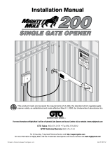
Multiple Panel Installations
Using the table and map, you can determine
the number of gate open/close cycles per day
to be expected in your area, using either one,
two, three or four panels. Figures are shown
for winter (minimum sunlight) and do not
account for use of any accessory items.
Solar Zones and Gate Activity
Estimated Minimum Gate Openings Per Day
300 m amp / hour (per panel) @ 18-22 volts
300 m amp / hour (per pair) @ 36-44 volts
18 volt systems
(GTO/PRO dealers only)
Winter Ratings Zone 1 Zone 2 Zone 3
PRO 1000; Mighty Mule (1 panel) 4 8 13
PRO 1000; Mighty Mule (2 panel ) 11 19 29
PRO 1000; Mighty Mule (3 panels) 18 30 45
PRO 1200 Dual Gates (2 panels) 7 13 20
PRO 1200 Dual Gates (3 panels) 11 20 30
PRO 1800 Single Gate (2 panels) 7 13 20
PRO 1800 Single Gate (4 panels) 14 26 40
PRO 1800 Dual Gates (2 panels) 4 8 13
PRO 1800 Dual Gates (4 panels) 8 16 26
NOTE: All connections should be weather proofed!
12 volt systems
Accessories will draw
additional power from
the battery; the more
accessories you have, the
more power they will
require.
Mighty Mule, GTO/PRO 1000, GTO/PRO 2000 and GTO/PRO SL-1000 connect in parallel.
GTO/PRO 1800 connect panels in series; connect paired panels in parallel.

/