Page is loading ...

PLEASE NOTE: Because of the various mounting applications, no mounting hardware is
provided with the GTO Automatic Gate Lock. All necessary mounting hardware can be
obtained from your local hardware store.
This manual shows two examples of the most common installations, and should provide
insight into most other applications. If you have any questions during installation, please call
(800) 543-1236 for technical support.
Installation Manual
IMPORTANT: Before you install the automatic gate lock be sure your gate is level, moves freely on
its hinges, and does not bind or drag against the ground.
Printed in China for GTO Access Systems, LLC © 2015 GTO
www.mightymule.com • www.gtoaccess.com
FM143-SL rev 11.30.15
Automatic
Gate Lock

2 Automatic Gate Lock Manual
FM143-SL rev 11.30.15
The installation has two parts:
(1) Mounting The Lock and Lock Receiver
(2) Connect to the Control Board
Once you have the necessary mounting hardware, you can begin the installation.
Before You Start...
For the Automatic Gate Lock to work properly, the gate must close rmly against a positive stop and engage the
lock catch against the lock receiver. Achieving optimal closure may require slight adjustments to the gate opener
settings.
Installing the lock with the Gate Opener may require resetting closed limits and changes to the stall force.
See
Setting the Gate Closed Position in your Gate Opener Installation Manual for information on these adjustments.
Set the limits so that the arm holds the gate snug against the stop in the closed position. IMPORTANT: You may
need to spray the locking mechanism with silicone spray initially to help the latch move freely.
If you are installing the lock on a Push-to-Open gate (gate opens out), the lock must be installed on the outside
of the gate. Depending upon the installation, the gate post may need to be "pocketed" to accommodate the
lock receiver or you may want to purchase the column mount receiver. Contact the GTO Technical Service
Department at (850) 575-4144 for assistance if needed.
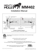
AUTOMATIC
GATE LOCK
®
D
E
F
G
H
I
J
K
L
M
C
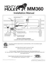
3½”
¼” Diameter
Optional
Column Mount Receiver
433IH (not included)
B
2”
2¾”
A
2”
5½”
8½”
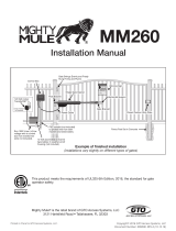
Be sure you have all the parts:
A - Lock with low voltage wire
B - Lock Receiver
C - Clevis Pin
D - Locking Cap
E - 6 nylon cable ties
F - Lock Keys (for manual release)
G - Lock Decal
What else do you need?
Mounting hardware is not included. Read these instructions completely and review the installation examples
to determine the mounting hardware required for your application.
NOTE: The Lock is designed to use mounting hardware up to
5
/16" in diameter. For a more secure installation,
use lock washers and lock nuts on all mounting hardware.
For most IRON or ALUMINUM TUBE gates you will need:
Carriage bolts, washers, and nuts for the lock and receiver. (See Illustration B, page 3)
For most CHAIN LINK gates you will need:
U-Bolts, saddles or carriage bolts, washers and nuts for the lock.
Bolts, washers, and nuts for the receiver. (See Illustration C, page 3)
NOTE: Positive stops are required for dual gate applications.

Automatic Gate Lock Manual 3
rev 11.30.15 FM143-SL
Installing The Gate Lock
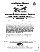
Illustration A
Lock and receiver must be level
and aligned with opener.
500
500
Step 1: With the gate in the closed position, determine the best location for the lock and lock receiver. The
lock and receiver must be level and aligned with the opener. Also, the lock should have a solid sur-
face or cross member to provide stability.
Step 2: Clamp receiver or position (see page 5, step 3) and lock together (with receiver pin hole and lock
slot aligned) against the gate post, mark their positions to drill receiver holes (See Illustration B and C,
page 4). The receiver must be mounted with carriage bolts, not U-bolts, to allow lock to seat properly.
Fasten the receiver to the gate post.
Step 3: Hold latch open with key to operate gate and check closed limit and lock alignment. Drop pin in
receiver but don't put the cap on. Recheck the lock's position and alignment, then mark its position
for drilling holes.
Step 4: Drill the holes on gate supports through the slots in the lock bracket. U-bolts and saddles can be
used to mount the lock on chain link gate supports. Secure the lock to the gate. Install clevis pin and
locking cap by placing clevis pin through slots in lock receiver and hammering the clevis pin into the
locking cap (See Illustration D page 4), secure the lock bracket and check the alignment again.
NOTE: The Automatic Gate Lock can be installed on single and dual gate systems. Use the appropriate
instructions for the system you have - SINGLE GATE (below) or DUAL GATES (page 4).
Turn power switch OFF on the bottom of the control box. Disconnect gate opener by removing hairpin
clip and clevis pin from the gate bracket end of the opener. Disconnecting the opener will allow the
gate to swing freely during installation of the gate lock.
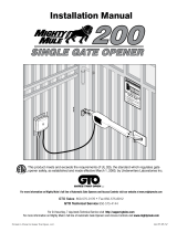
Single Gate Installation

4 Automatic Gate Lock Manual
FM143-SL rev 11.30.15
Clevis Pin
Receiver
Locking Cap
Lock
U-bolts, saddles & nuts
(not provided)
Added cross member
to support lock from
force of slammimg shut
Remember to check the alignment and mark positions before
drilling holes in fence post .
Illustration B
Iron or Aluminum Tube Fence and Gate Installation
Illustration C
Chain Link Fence and Gate Installation
Illustration D
Locking Cap Assembly
Clevis Pin
Receiver
Locking Cap
GTO Automatic
Gate Lock
Carriage bolts, washers, and nuts
(not provided; size of
fasteners depends on the gate)
Remember to check the alignment and mark positions
before drilling holes in fence post and gate.

Automatic Gate Lock Manual 5
rev 11.30.15 FM143-SL
Turn power switch OFF on the bottom of the control box. Disconnect gate openers by removing hairpin clip
and clevis pin from the gate bracket end of the openers. Disconnecting the openers will allow the gates to
swing freely during installation of the gate lock.
NOTE: In a DUAL GATE INSTALLATION the gate opener on the same side of the driveway as the control box
is known as the MASTER GATE OPENER and the gate is the MASTER GATE. Conversely the gate opener on the
other gate is referred to as the SECOND GATE OPENER and the gate the SECOND GATE.
Step 1: IMPORTANT: To use the gate lock on a dual gate system, the gate sequencing must be set so the
MASTER GATE opens rst and closes last, and the gate lock has to be mounted on the MASTER GATE
and the lock receiver is mounted on the SECOND GATE. The SECOND GATE requires a positive
stop (See illustration on page 5). If your gates are not sequenced in a manner that works like this,
you’ll have to change the sequencing DIP switches on your gate opener control board. Follow the
instructions in your gate opener installation manual for programming dual gate sequencing.
Contact GTO Technical Service at 1-800-543-1236 for additional information.
Dual Gate Installation
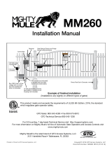
Step 2: With the gate in the closed position, determine the best location for the lock and lock receiver.
The lock and receiver must be level and aligned with the opener. Also, the lock should have a solid
surface or cross member to provide stability.
Step 3: Position receiver and lock together (with receiver pin hole and lock slot aligned) to the gates, mark
their positions to drill holes (see Illustration E and F, page 6). The receiver must be mounted on the
SECOND GATE with carriage bolts, not U-bolts, to allow lock to seat properly.
Step 4: Recheck the lock's position and alignment. Hold latch open with key and operate gate. Drill the
holes on gate supports through the slots in the lock bracket. U-bolts and saddles can be used to
mount the lock on chain link gate supports. Secure the lock to the MASTER GATE. Install clevis pin
and locking cap by placing clevis pin through slots in lock receiver and hammering the clevis pin
into the locking cap (see Illustration G), secure the lock bracket and check the alignment again.
With the sequencing set correctly follow the steps and diagrams below to mount the lock to the gates.
REFER TO YOUR OPENER’S MANUAL FOR DIP SWITCH SETTINGS.

6 Automatic Gate Lock Manual
FM143-SL rev 11.30.15
Lock and receiver must be level and aligned with opener.
Hold latch open with key to operate gate.
Receiver pin hole and lock slot must line up.
MASTER GATE
SLAVE GATE
(second gate opener) (first gate opener)
500
500
500
Lock and receiver must be level and aligned with opener.
Hold latch open with key to operate gate.
Receiver pin hole and lock slot must line up.
MASTER GATE
SLAVE GATE
(second gate opener) (first gate opener)
500
500
500
Illustration E

Automatic Gate Lock Manual 7
rev 11.30.15 FM143-SL
Locking Cap
Assembly
Clevis Pin
Receiver
Locking Cap
Lock
U-bolts, saddles & nuts
(not provided)
Added cross member
to support lock from
force of slammimg shut
Remember to check the alignment and mark positions before
drilling holes in fence post .
Illustration F
Illustration G
Manual Lock Release:
The GTO Automatic Gate Lock is keyed for manual release.
Should the electronic release be disabled for any reason, simply
use the key to manually open the lock.
Troubleshooting
If lock hangs up and does not latch properly try the following steps before contacting Technical Support:
• Reset closed position limit so gate is snug against stop plate
• Lubricate latch with silicone spray to help latch to operate freely
• Check alignment of lock by using the key to hold the latch open while operating the gate opener
• Make sure you have a positive stop installed on dual gate system (see page 5).
If lock still does not operate properly contact the GTO Technical Support Department:
Hours: MON - FRI 8:00AM - 7:00PM (ET)
(800) 543-1236
(850) 575-4144

GTO Access Systems, LLC • 3121 Hartsfield Road • Tallahassee, Florida 32303
www.mightymule.com • www.gtoaccess.com
For online Technical Support visit the Online Troubleshooter Wizard 24 hrs/day 7 days/week at
http://support.gtoinc.com/support/troubleshooter.aspx and open a Tech Ticket
Technical Support Hours: MON - FRI 8:00AM - 7:00PM (ET)
1-800-543-1236
Limited One Year Warranty:
GTO Access Systems, LLC’s, gate opener accessories are warranted by the manufacturer against defects in workmanship for a
period of one (1) year from the date of purchase, provided recommended installation procedures have been followed.
In the case of product failure due to defective material or manufacturer workmanship within the one (1) year warranty period, the
accessory will be repaired or replaced (at the manufacturer's option) at no charge to the customer, if returned freight prepaid to
GTO, 3121 Hartseld Rd., Tallahassee, FL 32303.
IMPORTANT: Call (800) 543-1236 for a Return Goods Authorization (RGA) number before returning accessory to factory. Products
received at the factory without an RGA will not be accepted. Replacement or repaired parts are covered by this warranty for the
remainder of the one (1) year warranty period or six (6) months, whichever is greater. GTO will pay the shipping costs (equivalent
to United Parcel Service ground rate) for items repaired under warranty.
The manufacturer will not be responsible for any charges or damages incurred in the removal of the defective parts for repair,
or for the reinstallation of those parts after repair. This warranty shall be considered void if damage to the product(s) was due to
improper installation or use, connection to an improper power source, or if damage was caused by lightning, wind, re, ood,
insects, or other natural agent.
After the one (1) year warranty period, GTO or one of its authorized service centers will make any necessary repairs for a nominal
fee. Call GTO at (800) 543-1236 for more information. This warranty gives you specic legal rights, and you may also have other
rights which may vary from state to state. This warranty is in lieu of all other warranties, expressed or implied. NOTE: Verication of
the warranty period requires copies of receipts or other proof of purchase. Please retain those records.
IMPORTANT:
For the optimum service and safety, nd the ideal obstruction
sensing setting for your gate opener. Depending on the weight of your gate,
the ideal setting will be just enough to move your gate without self-obstruction
(stopping or reversing due to its own weight), yet sensitive enough to reverse and
stop when it meets with an obstruction such as a car. See the GTO Installation Manual
for information on obstruction settings.
NOTE: Be sure your gate moves freely on its hinges without binding or dragging.
/